HP ProLiant BL685c Generation 5 Server Blade Maintenance and Service Guide Abstract This guide describes identification and maintenance procedures, diagnostic tools, specifications and requirements for hardware components and software. This guide is for an experienced service technician. HP assumes you are qualified in the servicing of computer equipment, trained in recognizing hazards in products, and are familiar with weight and stability precautions.
© Copyright 2008, 2011 Hewlett-Packard Development Company, L.P. The information contained herein is subject to change without notice. The only warranties for HP products and services are set forth in the express warranty statements accompanying such products and services. Nothing herein should be construed as constituting an additional warranty. HP shall not be liable for technical or editorial errors or omissions contained herein. Microsoft® and Windows® are U.S.
Contents Customer self repair ...................................................................................................................... 5 Parts only warranty service ............................................................................................................................ 5 Illustrated parts catalog ............................................................................................................... 16 Server blade components ........................................
Component identification ............................................................................................................. 56 Front panel components .............................................................................................................................. 56 Front panel LEDs ........................................................................................................................................ 57 SAS and SATA hard drive LEDs ...................................
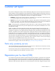
Customer self repair HP products are designed with many Customer Self Repair (CSR) parts to minimize repair time and allow for greater flexibility in performing defective parts replacement. If during the diagnosis period HP (or HP service providers or service partners) identifies that the repair can be accomplished by the use of a CSR part, HP will ship that part directly to you for replacement. There are two categories of CSR parts: • Mandatory—Parts for which customer self repair is mandatory.
Obligatoire - Pièces pour lesquelles la réparation par le client est obligatoire. Si vous demandez à HP de remplacer ces pièces, les coûts de déplacement et main d'œuvre du service vous seront facturés. Facultatif - Pièces pour lesquelles la réparation par le client est facultative. Ces pièces sont également conçues pour permettre au client d'effectuer lui-même la réparation.
In base alla disponibilità e alla località geografica, le parti CSR vengono spedite con consegna entro il giorno lavorativo seguente. La consegna nel giorno stesso o entro quattro ore è offerta con un supplemento di costo solo in alcune zone. In caso di necessità si può richiedere l'assistenza telefonica di un addetto del centro di supporto tecnico HP. Nel materiale fornito con una parte di ricambio CSR, HP specifica se il cliente deve restituire dei componenti.
defekte Teil nicht zurückschicken, kann HP Ihnen das Ersatzteil in Rechnung stellen. Im Falle von Customer Self Repair kommt HP für alle Kosten für die Lieferung und Rücksendung auf und bestimmt den Kurier-/Frachtdienst. Weitere Informationen über das HP Customer Self Repair Programm erhalten Sie von Ihrem Servicepartner vor Ort. Informationen über das CSR-Programm in Nordamerika finden Sie auf der HP Website unter (http://www.hp.com/go/selfrepair).
enviara el componente defectuoso requerido, HP podrá cobrarle por el de sustitución. En el caso de todas sustituciones que lleve a cabo el cliente, HP se hará cargo de todos los gastos de envío y devolución de componentes y escogerá la empresa de transporte que se utilice para dicho servicio. Para obtener más información acerca del programa de Reparaciones del propio cliente de HP, póngase en contacto con su proveedor de servicios local.
Neem contact op met een Service Partner voor meer informatie over het Customer Self Repair programma van HP. Informatie over Service Partners vindt u op de HP website (http://www.hp.com/go/selfrepair). Garantieservice "Parts Only" Het is mogelijk dat de HP garantie alleen de garantieservice "Parts Only" omvat. Volgens de bepalingen van de Parts Only garantieservice zal HP kosteloos vervangende onderdelen ter beschikking stellen.
No caso desse serviço, a substituição de peças CSR é obrigatória. Se desejar que a HP substitua essas peças, serão cobradas as despesas de transporte e mão-de-obra do serviço.
Customer self repair 12
Customer self repair 13
Customer self repair 14
Customer self repair 15
Illustrated parts catalog Server blade components Item Description Spare part number Customer self repair (on page 5) 1 Heatsink 436380-001 Optional2 2 Processor — — a) 1.9-GHz AMD Opteron™ Model 8347 HE* ** 457127-001 Optional2 b) 2.2-GHz AMD Opteron™ Model 8354* ** 448404-001 Optional2 c) 2.3-GHz AMD Opteron™ Model 8356* ** 448405-001 Optional2 d) 2.3-GHz AMD Opteron™ Model 8376 HE* ** 518005-001 Optional2 e) 2.6-GHz AMD Opteron™ Model 8382* ** 508592-001 Optional2 f) 2.
Item Description Spare part number Customer self repair (on page 5) b) 1-GB, PC2-5300 DIMM* 416356-001 Mandatory1 c) 2-GB, PC2-5300 DIMM* 432668-001 Mandatory1 d) 2-GB, PC2-5300, low-power, registered DIMM* 416357-001 Mandatory1 e) 2-GB, PC2- 5300, DDR2 2x1GB, low power DIMM, single rank kit* f) 2-GB, PC2-6400, DDR2 2x1GB DIMM kit* 488608-001 Mandatory1 501156-001 Mandatory1 g) 4-GB, PC2-5300 DIMM* 432670-001 Mandatory1 h) 4-GB, PC2-5300, low-power, registered DIMM (RoHS)* 487945-001
Item Description Spare part number Customer self repair (on page 5) 11 System battery, lithium, 3V* 234556-001 Mandatory1 12 SAS cable* 439329-001 Mandatory1 13 HP c-Class Blade SUV Cable* 416003-001 Mandatory1 14 Mezzanine card options* — — 15 16 a) Emulex LPe1105-HP 4Gb FC HBA for HP c-Class BladeSystem 405921-001 Mandatory1 b) QLogic QMH2462 4Gb FC HBA for HP c-Class BladeSystem 405920-001 Mandatory1 c) HP NC325m PCI Express Quad Port Gigabit Server Adapter for c-Class BladeSyst
Optional—Parts for which customer self repair is optional. These parts are also designed for customer self repair. If, however, you require that HP replace them for you, there may or may not be additional charges, depending on the type of warranty service designated for your product. 3 No—Some HP parts are not designed for customer self repair. In order to satisfy the customer warranty, HP requires that an authorized service provider replace the part.
Optional: Opcional—Peças cujo reparo feito pelo cliente é opcional. Essas peças também são projetadas para o reparo feito pelo cliente. No entanto, se desejar que a HP as substitua, pode haver ou não a cobrança de taxa adicional, dependendo do tipo de serviço de garantia destinado ao produto. 3 No: Nenhuma—Algumas peças da HP não são projetadas para o reparo feito pelo cliente. A fim de cumprir a garantia do cliente, a HP exige que um técnico autorizado substitua a peça.
Removal and replacement procedures Required tools You need the following items for some procedures: • T-15 Torx screwdriver • Diagnostics Utility ("Array Diagnostic Utility" on page 54) Safety considerations Before performing service procedures, review all the safety information. Preventing electrostatic discharge To prevent damaging the system, be aware of the precautions you need to follow when setting up the system or handling parts.
Symbols on equipment The following symbols may be placed on equipment to indicate the presence of potentially hazardous conditions. This symbol indicates the presence of hazardous energy circuits or electric shock hazards. Refer all servicing to qualified personnel. WARNING: To reduce the risk of injury from electric shock hazards, do not open this enclosure. Refer all maintenance, upgrades, and servicing to qualified personnel. This symbol indicates the presence of electric shock hazards.
• Press and release the Power On/Standby button. This method initiates a controlled shutdown of applications and the OS before the server blade enters standby mode. • Press and hold the Power On/Standby button for more than 4 seconds to force the server blade to enter standby mode. This method forces the server blade to enter standby mode without properly exiting applications and the OS. It provides an emergency shutdown method if an application stops responding.
3. Remove the server blade. 4. Place the server blade on a flat, level work surface. WARNING: To reduce the risk of personal injury from hot surfaces, allow the drives and the internal system components to cool before touching them. CAUTION: To prevent damage to electrical components, properly ground the server blade before beginning any installation procedure. Improper grounding can cause ESD. Access panel To remove the component: 1. Power down the server blade (on page 22). 2.
Hard drive blank Remove the component as indicated. To replace the component, reverse the removal procedure. Hard drive 1. Determine the status of the hard drive from the hot-plug SAS hard drive LED combinations ("SAS and SATA hard drive LED combinations" on page 58). 2. Back up all server data. 3. Remove the hard drive. To replace the component, reverse the removal procedure.
DIMM baffle CAUTION: To avoid damage to the server blade and the enclosure, install all DIMM baffles in the proper location after adding or replacing DIMMs. DIMM baffles that are missing or installed incorrectly can compromise server blade and enclosure cooling. To remove the component: 1. Power down the server blade (on page 22). 2. Remove the server blade (on page 23). 3. Remove the access panel ("Access panel" on page 24). 4. Remove the DIMM baffle.
CAUTION: Use only HP DIMMs. DIMMs from other sources may adversely affect data integrity. To remove the component: 1. Power down the server blade (on page 22). 2. Remove the server blade (on page 23). 3. Remove the access panel ("Access panel" on page 24). 4. Remove all DIMM baffles ("DIMM baffle" on page 26). 5. Remove the DIMM. To replace the component: 1. Install the DIMM. 2. Install the DIMM baffle ("DIMM baffle" on page 26). 3. Install the access panel ("Access panel" on page 24). 4.
4. Remove the mezzanine card. CAUTION: To prevent damage to the server blade, apply pressure over the mezzanine connector when installing the mezzanine card. Do not apply pressure to the edges of the card. To replace the component, reverse the removal procedure. HP Smart Array E200i Controller cache module To remove the component: 1. Power down the server blade (on page 22). 2. Remove the server blade (on page 23). 3. Remove the access panel ("Access panel" on page 24). 4. Remove the cache module.
To replace the component, reverse the removal procedure. HP Smart Array E200i Controller cache module battery pack To remove the component: 1. Power down the server blade (on page 22). 2. Remove the server blade (on page 23). 3. Remove the access panel ("Access panel" on page 24). 4. Remove the cache module ("HP Smart Array E200i Controller cache module" on page 28). 5. Remove the battery pack. To replace the component, reverse the removal procedure. SAS cable To remove the component: 1.
4. Remove the SAS cable. To replace the component, reverse the removal procedure. Hard drive backplane To remove the component: 1. Power down the server blade (on page 22). 2. Remove the server blade (on page 23). CAUTION: Remove all hard drives and hard drive blanks before removing the hard drive backplane. 3. Remove all hard drives ("Hard drive" on page 25). 4. Remove all hard drive blanks ("Hard drive blank" on page 25). 5. Remove the access panel ("Access panel" on page 24). 6.
7. Remove the hard drive backplane. To replace the component, reverse the removal procedure. Front panel/hard drive cage assembly To remove the component: 1. Power down the server blade (on page 22). 2. Remove the server blade (on page 23). 3. Remove the access panel ("Access panel" on page 24). 4. Remove all hard drives ("Hard drive" on page 25). 5. Remove all hard drive blanks ("Hard drive blank" on page 25). 6. Remove the front panel/hard drive cage assembly.
Server blade handle To remove the component: 1. Power down the server blade (on page 22). 2. Remove the server blade (on page 23). 3. Remove the access panel ("Access panel" on page 24). 4. Remove all hard drives ("Hard drive" on page 25). 5. Remove all hard drive blanks ("Hard drive blank" on page 25). 6. Remove the front panel/hard drive cage assembly ("Front panel/hard drive cage assembly" on page 31). 7. Remove the server blade handle.
7. Remove the release button. To replace the component, reverse the removal procedure. Heatsink IMPORTANT: Do not install the air baffles on heatsinks for processors 3 and 4. To remove the component: 1. Power down the server blade (on page 22). 2. Remove the server blade (on page 23). 3. Remove the access panel ("Access panel" on page 24). 4. Remove the SAS cable, if installed ("SAS cable" on page 29). 5.
o Processor 3 or 4 o Processor 1 or 2 To replace the component: 1. Clean the old thermal grease from the processor with the alcohol swab. Allow the alcohol to evaporate before continuing.
2. Remove the thermal interface protective cover from the heatsink. IMPORTANT: Do not install the air baffles on heatsinks for processors 3 and 4. 3. If the heatsink will be installed on processor 1 or 2, expose the adhesive and apply the air baffles to the side of the heatsink that will face the center of the server. 4. Align the holes in the heatsink with the guide pins on the processor cage.
o Processor 3 or 4 o Processor 1 or 2 CAUTION: Heatsink retaining screws should be tightened in diagonally opposite pairs (in an "X" pattern). 5.
o Processor 3 or 4 o Processor 1 or 2 6. Install the SAS cable, if removed ("SAS cable" on page 29). 7. Install the access panel ("Access panel" on page 24). Processor WARNING: To reduce the risk of personal injury from hot surfaces, allow the drives and the internal system components to cool before touching them. CAUTION: To prevent possible server malfunction, do not mix processors of different speeds or cache sizes. Refer to the label on the processor heatsink for a description of the processor.
CAUTION: The server blade supports only two- or four-processor configurations. Always populate processor sockets 1 and 2 with processors and heatsinks. To prevent overheating, always populate processor sockets 3 and 4 with processors and heatsinks or processor socket covers and heatsink blanks. To remove the component: 1. Power down the server blade (on page 22). 2. Remove the server blade (on page 23). 3. Remove the access panel ("Access panel" on page 24). 4.
To replace the component: CAUTION: The pins on the processor socket are very fragile. Any damage to them may require replacing the system board. CAUTION: Failure to completely open the processor locking lever prevents the processor from seating during installation, leading to hardware damage. IMPORTANT: Be sure the processor remains inside the processor installation tool. 1. If the processor has separated from the installation tool, carefully re-insert the processor in the tool. 2.
3. Press down firmly until the processor installation tool clicks and separates from the processor, and then remove the processor installation tool.
4. Close the processor retaining bracket and the processor retaining latch. 5. Clean the old thermal grease from the heatsink with the alcohol swab. Allow the alcohol to evaporate before continuing. 6. Apply all the grease to the top of the processor in the following pattern to ensure even distribution. CAUTION: The heatsink thermal interface media is not reusable and must be replaced if the heatsink is removed from the processor after it has been installed.
o Processor 3 or 4 o Processor 1 or 2 CAUTION: Heatsink retaining screws should be tightened in diagonally opposite pairs (in an "X" pattern). 8.
o Processor 3 or 4 o Processor 1 or 2 9. Install the SAS cable, if removed ("SAS cable" on page 29). 10. Install the access panel ("Access panel" on page 24). 11. Install the server blade. System battery If the server blade no longer automatically displays the correct date and time, you may need to replace the battery that provides power to the real-time clock. Under normal use, battery life is 5 to 10 years.
WARNING: The computer contains an internal lithium manganese dioxide, a vanadium pentoxide, or an alkaline battery pack. A risk of fire and burns exists if the battery pack is not properly handled. To reduce the risk of personal injury: • • • • Do not attempt to recharge the battery. Do not expose the battery to temperatures higher than 60°C (140°F). Do not disassemble, crush, puncture, short external contacts, or dispose of in fire or water. Replace only with the spare designated for this product.
7. Remove the hard drive backplane ("Hard drive backplane" on page 30). 8. Remove the front panel/hard drive cage assembly ("Front panel/hard drive cage assembly" on page 31). 9. Remove all DIMM baffles ("DIMM baffle" on page 26). 10. Remove the cache module ("HP Smart Array E200i Controller cache module" on page 28). 11. Remove all DIMMs ("DIMMs" on page 26). 12. Remove any installed mezzanine cards ("Mezzanine card" on page 27). 13. Remove the heatsink ("Heatsink" on page 33). 14.
CAUTION: To avoid damage to the system board: • Do not touch the processor socket contacts. • Always install the processor socket cover after removing the processor from the socket. • Do not tilt or slide the processor when lowering the processor into the socket. CAUTION: To avoid damage to the processor: • Handle the processor only by the edges. • Do not touch the bottom of the processor, especially the contact area. 16. Remove the failed system board. To replace the system board: 1.
a. Remove the processor socket protective cover. b. Open the processor retaining latch and the processor socket retaining bracket. 3. Install the processor socket cover onto the processor socket of the failed system board. 4. Install the processor on the spare system board. CAUTION: The processor is designed to fit one way into the socket. Use the alignment guides on the processor and socket to properly align the processor with the socket. Refer to the server blade hood label for specific instructions.
5. Close the processor retaining latch and the processor socket retaining bracket. 6. Clean the old thermal grease from the heatsink and the top of the processor with the alcohol swab. Allow the alcohol to evaporate before continuing. 7. Apply all the grease to the top of the processor in the following pattern to ensure even distribution. CAUTION: The heatsink thermal interface media is not reusable and must be replaced if the heatsink is removed from the processor after it has been installed.
IMPORTANT: When replacing multiple processors, install heatsinks with attached air baffles on processors 1 and 2 only. 8. Install the heatsink. IMPORTANT: Install all components with the same configuration that was used on the failed system board. 9. Install all components removed from the failed system board. 10. Install hard drives or hard drive blanks into each bay. 11. Install the access panel ("Access panel" on page 24). 12. Install the server blade.
Cabling SAS cable routing Using the HP c-Class Blade SUV Cable The HP c-Class Blade SUV Cable enables the user to perform server blade administration, configuration, and diagnostic procedures by connecting video and USB devices directly to the server blade. For SUV cable connectors, see "HP c-Class Blade SUV Cable (on page 62).
CAUTION: Before disconnecting the SUV cable from the connector, always squeeze the release buttons on the sides of the connector. Failure to do so can result in damage to the equipment. NOTE: For this configuration, a USB hub is not necessary. To connect additional devices, use a USB hub. 1. Connect the SUV cable to the server blade. 2. Connect the video connector to a monitor. 3. Connect a USB mouse to one USB connector. 4. Connect a USB keyboard to the second USB connector.
o USB diskette drive NOTE: Use a USB hub when connecting a USB diskette drive and/or USB CD-ROM drive to the server blade. The USB hub provides additional connections.
Diagnostic tools Troubleshooting resources The HP ProLiant Servers Troubleshooting Guide provides procedures for resolving common problems and comprehensive courses of action for fault isolation and identification, error message interpretation, issue resolution, and software maintenance on ProLiant servers and server blades. This guide includes problem-specific flowcharts to help you navigate complex troubleshooting processes. To view the guide, select a language: • English (http://www.hp.
• From within Survey Utility • From within operating system-specific IML viewers o For NetWare: IML Viewer (does not apply to HP ProLiant DL980 Servers) o For Windows®: IML Viewer o For Linux: IML Viewer Application • From within the iLO 2 user interface • From within HP Insight Diagnostics (on page 53) For more information, see the Management CD or DVD in the HP Insight Foundation suite for ProLiant.
For additional security, external USB functionality can be disabled through RBSU. Disabling external USB support in RBSU disables the USB connectors on the HP c-Class Blade SUV Cable.
Component identification Front panel components Item Description 1 Hard drive bay 2 2 Server blade handle 3 Server blade handle release button 4 Serial pull tab 5 Hard drive bay 1 6 HP c-Class Blade SUV cable connector* 7 Power On/Standby button * The SUV connector and the HP c-Class Blade SUV Cable are for some server blade configuration and diagnostic procedures.
Front panel LEDs Item Description Status 1 UID LED Blue = Identified Blue flashing = Active remote management Off = No active remote management 2 Health LED Green = Normal operation Amber flashing = Degraded condition Red flashing = Critical condition 3 NIC 1 LED* Green = Network linked Green flashing = Network activity Off = No link or activity 4 NIC 2 LED* Green = Network linked Green flashing = Network activity Off = No link or activity 5 NIC 3 LED* Green = Network linked Green flashing
SAS and SATA hard drive LEDs Item Description 1 Fault/UID LED (amber/blue) 2 Online LED (green) SAS and SATA hard drive LED combinations Online/activity LED (green) Fault/UID LED (amber/blue) Interpretation On, off, or flashing Alternating amber and blue The drive has failed, or a predictive failure alert has been received for this drive; it also has been selected by a management application.
Online/activity LED (green) Fault/UID LED (amber/blue) Interpretation Off Steadily amber A critical fault condition has been identified for this drive, and the controller has placed it offline. Replace the drive as soon as possible. Off Amber, flashing regularly (1 Hz) A predictive failure alert has been received for this drive. Replace the drive as soon as possible. Off Off The drive is offline, a spare, or not configured as part of an array.
Item Description 18 SAS cable 19 Processor socket 1 (populated) 20 DIMM slots (Processor 1 memory banks A and B) 21 System battery 22 DIMM slots (Processor 3 memory banks E and F) 23 Processor socket 3 24 System board thumbscrew 25 System maintenance switch (SW2) 26 Hard drive backplane connector The symbols correspond to the symbols located on the interconnect bays.
System maintenance switch Position Function Default 1* iLO 2 security override Off 2 Configuration lock Off 3 Reserved Off 4 Reserved Off 5* Password disabled Off 6* Reset configuration Off 7 Reserved Off 8 Reserved Off *To access redundant ROM, set S1, S5, and S6 to ON.
If the system ROM is corrupted, the system automatically switches to the redundant ROM in most cases. If the system does not automatically switch to the redundant ROM, perform the following steps: 1. Power down the server blade (on page 22). 2. Remove the server blade (on page 23). 3. Remove the access panel ("Access panel" on page 24). 4. Change positions 1, 5, and 6 of the system maintenance switch to on. 5. Install the access panel ("Access panel" on page 24). 6.
Specifications Environmental specifications Specification Value — Temperature range* Operating 10°C to 35°C (50°F to 95°F) Non-operating -30°C to 60°C (-22°F to 140°F) Relative humidity (noncondensing)** — Operating 10% to 90% @ 28°C (82.4°F) Non-operating 5% to 95% @ 38.7°C (101.7°F) Altitude† — Operating 3050 m (10,000 ft) Non-operating 9144 m (30,000 ft) * The following temperature conditions and limitations apply: - All temperature ratings shown are for sea level.
Acronyms and abbreviations ADU Array Diagnostics Utility CSR Customer Self Repair DIMM dual inline memory module ESD electrostatic discharge FC Fibre Channel HBA host bus adapter I/O input/output iLO 2 Integrated Lights-Out 2 IML Integrated Management Log NIC network interface controller PCIe peripheral component interconnect express RBSU ROM-Based Setup Utility Acronyms and abbreviations 64
SAS serial attached SCSI SATA serial ATA SFF small form-factor SIM Systems Insight Manager UID unit identification USB universal serial bus Acronyms and abbreviations 65
Index A access panel 24 ADU (Array Diagnostic Utility) 54 B battery 43 battery pack, removing 29 battery-backed write cache battery pack 29 buttons 56 C cables 29, 50 cabling 50 cache module 28 cautions 21 components 16, 21, 24, 56, 59 components, identification 56, 59 connectors 56, 60 CSR (customer self repair) 5 D diagnostic tools 53 diagnostics utility 53 DIMM baffles 26 DIMM slots 60 DIMMs 26 E electrostatic discharge 21 F features 56 front panel components 56 front panel LEDs 57 front panel/hard
ROM redundancy 61 S safety considerations 21 safety information 21 SAS drives 25, 58 SAS hard drive LEDs 58 SAS/SATA LED combinations 58 SATA hard drive 58 SATA hard drive LEDs 58 server blade components 56 server blade handle 32 specifications 63 specifications, environmental 63 static electricity 21 symbols on equipment 22 system battery 43 system board 44 system board battery 43 system board components 59, 61 system maintenance switch 61 T tools 21, 53 troubleshooting 53 U USB connectors 62 USB suppor