HP ProLiant BL685c G6 Server Blade User Guide Part Number 508505-001 April 2009 (First Edition)
© Copyright 2009 Hewlett-Packard Development Company, L.P. The information contained herein is subject to change without notice. The only warranties for HP products and services are set forth in the express warranty statements accompanying such products and services. Nothing herein should be construed as constituting an additional warranty. HP shall not be liable for technical or editorial errors or omissions contained herein. Microsoft, Windows, and Windows Server are U.S.
Contents Component identification ............................................................................................................... 7 Front panel components ............................................................................................................................. 7 Front panel LEDs ....................................................................................................................................... 7 SAS and SATA hard drive LEDs.............................
Installing the Trusted Platform Module board ..................................................................................... 49 Retaining the recovery key/password .............................................................................................. 50 Enabling the Trusted Platform Module............................................................................................... 51 Cabling ....................................................................................................
Change control and proactive notification ........................................................................................ 74 Care Pack .................................................................................................................................... 74 Troubleshooting .......................................................................................................................... 75 Troubleshooting resources ..............................................................
Index.......................................................................................................................................
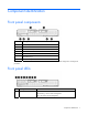
Component identification Front panel components Item Description 1 Serial label pull tab 2 HP c-Class Blade SUV Cable connector* 3 Power On/Standby button and LED 4 Server blade release button 5 Server blade release lever 6 Hard drive bay 2 7 Hard drive bay 1 * The SUV connector and the HP c-Class Blade SUV Cable are for some server blade configuration and diagnostic procedures.
Item Description Status 2 Health LED Green = Normal operation Amber flashing = Degraded condition Red flashing = Critical condition 3 Flex 1 LED Green = Network linked Green flashing = Network activity Off = No link or activity 4 Flex 2 LED Green = Network linked Green flashing = Network activity Off = No link or activity 5 Flex 3 LED Green = Network linked Green flashing = Network activity Off = No link or activity 6 Flex 4 LED Green = Network linked Green flashing = Network activity Off =
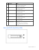
Item Description 1 Fault/UID LED (amber/blue) 2 Online LED (green) SAS and SATA hard drive LED combinations NOTE: Predictive failure alerts can occur only when the hard drive is connected to a Smart Array controller. Online/activity LED (green) Fault/UID LED (amber/blue) Interpretation On, off, or flashing Alternating amber and blue The drive has failed, or a predictive failure alert has been received for this drive; it also has been selected by a management application.
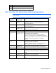
System board components Item Description 1 Processor 4 DIMM slots 2 Processor socket 4 3 Processor socket 2 (populated) 4 System maintenance switch 5 Processor 2 DIMM slots 6 Mezzanine connector 1 (Type I mezzanine only) 7 Mezzanine connector 2 (Type I or Type II mezzanine) 8 System board thumbscrews (3) 9 Enclosure connectors (2) 10 SSD data connectors (2) 11 Internal USB connector 12 Mezzanine connector 3 (Type I or Type II mezzanine) 13 SD card slot 14 TPM connector 15 SSD
correspond to the symbols located on the interconnect bays. For more information, see the The symbols HP ProLiant BL685c G6 Server Blade Installation Instructions that ship with the server blade. DIMM slots DIMM slots are identified by the numbers 1 through 32 and paired banks are identified by the letters A through P.
• Processor 3 DIMM slots • Processor 4 DIMM slots For installation guidelines and population order, see "Memory option (on page 37)." Mezzanine connector definitions PCIe x8 mezzanine connectors support x16 cards at up to x8 speeds.
System maintenance switch Position Function Default 1* iLO 2 security override Off 2 Configuration lock Off 3 Reserved Off 4 Reserved Off 5* Password disabled Off 6* Reset configuration Off 7 Reserved Off 8 Reserved Off *To access redundant ROM, set S1, S5, and S6 to ON.
Accessing the redundant ROM If the system ROM is corrupted, the system automatically switches to the redundant ROM in most cases. If the system does not automatically switch to the redundant ROM, perform the following steps: 1. Power down the server blade (on page 15). 2. Remove the server blade (on page 16). 3. Remove the access panel (on page 17). 4. Change positions 1, 5, and 6 of the system maintenance switch to on. 5. Install the access panel. 6.
Operations Power up the server blade The Onboard Administrator initiates an automatic power-up sequence when the server blade is installed. If the default setting is changed, use one of the following methods to power up the server blade: • Use a virtual power button selection through iLO 2. • Press and release the Power On/Standby button. When the server blade goes from the standby mode to the full power mode, the system power LED changes from amber to green.
• Use the Onboard Administrator GUI to initiate a shutdown: a. Select the Enclosure Information tab, then select the Overall checkbox in the Device Bays item. b. Initiate a shutdown from the Virtual Power menu: — Select Momentary Press to initiate a controlled shutdown of applications and the OS. — Select Press and Hold to initiate an emergency shutdown of applications and the OS. IMPORTANT: When the server blade are in standby mode, auxiliary power is still being provided.
Remove the access panel To remove the component: 1. Power down the server blade (on page 15). 2. Remove the server blade (on page 16). 3. Press the access panel release button, and then slide the access panel to the rear. 4. Remove the access panel. WARNING: To reduce the risk of personal injury from hot surfaces, allow the drives and the internal system components to cool before touching them.
WARNING: To reduce the risk of personal injury from hot surfaces, allow the drives and the internal system components to cool before touching them. To remove the component: 1. Power down the server blade (on page 15). 2. Remove the server blade (on page 16). 3. Remove the access panel (on page 17). 4. Disconnect the SSD cables from the system board. 5. Remove the SSD.
CAUTION: To avoid damage to the server blade and the enclosure, install all DIMM baffles in the proper location after adding or replacing DIMMs. DIMM baffles that are missing or installed incorrectly can compromise server blade and enclosure cooling. To remove the component: 1. Power down the server blade (on page 15). 2. Remove the server blade (on page 16). 3. Remove the access panel (on page 17). 4. Remove the SSD drives, if installed ("Remove the solid state drive" on page 17). 5.
1. Install the DIMM baffles. 2. Install the SSD drives, if removed ("Solid state drive option" on page 39). 3. Install the access panel (on page 17). 4. Install the server blade ("Installing a server blade" on page 29, "Remove the server blade" on page 16).
Setup Overview Installation of a server blade requires the following steps: 1. Install and configure an HP BladeSystem c-Class enclosure. 2. Install any server blade options. 3. Install interconnect modules in the enclosure. 4. Connect the interconnect modules to the network. 5. Install a server blade. 6. Complete the server blade configuration. Installing an HP BladeSystem c-Class enclosure Before performing any server blade-specific procedures, install an HP BladeSystem c-Class enclosure.
1. Remove the device bay blank. 2. Remove the three adjacent blanks. Removing a c7000 device bay divider 1. Slide the device bay shelf locking tab to the left to open it.
2. Push the device bay shelf back until it stops, lift the right side slightly to disengage the two tabs from the divider wall, and then rotate the right edge downward (clockwise). 3. Lift the left side of the device bay shelf to disengage the three tabs from the divider wall, and then remove it from the enclosure.
Removing a c3000 device bay mini-divider or device bay divider 1. Slide the locking tab down. 2. Remove the mini-divider or divider: o c3000 mini-divider: Push the divider toward the back of the enclosure until the divider drops out of the chassis. o c3000 divider: a. Push the divider toward the back of the enclosure until it stops. b. Slide the divider to the left to disengage the tabs from the wall. c. Rotate the divider clockwise.
d. Remove the divider from the enclosure. Removing a c3000 device bay divider 1. Remove the device bay blank. 2. Remove the three adjacent device bay blanks.
3. Slide the locking tab down. 4. Disengage the divider: a. Push the divider toward the back of the enclosure until it stops. b. Slide the divider to the left to disengage the tabs from the wall. c. Rotate the divider clockwise.
5. Remove the divider from the enclosure. Installing interconnect modules For specific steps to install interconnect modules, see the documentation that ships with the interconnect module.
• HP BladeSystem c3000 Enclosure To support network connections for specific signals, install an interconnect module in the bay corresponding to the embedded NIC or mezzanine signals.
Installing server blade options Before installing and initializing the server blade, install any server blade options, such as an additional processor, hard drive, or mezzanine card. Installing a server blade 1. Remove the connector covers. 2. Prepare the server blade for installation.
3. Install the server blade. Completing the configuration To complete the server blade and HP BladeSystem configuration, see the overview card that ships with the enclosure.
Hardware options installation Introduction If more than one option is being installed, read the installation instructions for all the hardware options and identify similar steps to streamline the installation process. WARNING: To reduce the risk of personal injury from hot surfaces, allow the drives and the internal system components to cool before touching them. CAUTION: To prevent damage to electrical components, properly ground the server before beginning any installation procedure.
IMPORTANT: Processor sockets 1 and 2 must always be populated. If either processor socket is empty, the server blade does not power up. To install a processor: 1. Power down the server blade (on page 15). 2. Remove the server blade (on page 16). 3. Remove the access panel (on page 17). 4. Remove the SAS hard drives ("Remove the SAS hard drive" on page 17), if installed. 5. Remove the SAS controller, if installed. 6. Remove the front bezel.
7. Remove the heatsink blank. Retain the heatsink blank for future use. CAUTION: The pins on the processor socket are very fragile. Any damage to them may require replacing the system board. 8. Remove the processor socket protective cover. Retain the cover for future use. CAUTION: Failure to completely open the processor retaining latch prevents the processor from seating during installation, leading to hardware damage.
9. Open the processor retaining latch and the processor socket retaining bracket. IMPORTANT: Be sure the processor remains inside the processor installation tool. 10. If the processor has separated from the installation tool, carefully re-insert the processor in the tool. 11. Align the processor installation tool with the socket and install the processor. CAUTION: The processor is designed to fit one way into the socket.
12. Press down firmly until the processor installation tool clicks and separates from the processor, and then remove the processor installation tool.
13. Close the processor retaining bracket and the processor retaining latch. 14. Remove the thermal interface protective cover from the heatsink. CAUTION: Heatsink retaining screws should be tightened in diagonally opposite pairs (in an "X" pattern). IMPORTANT: When installing the heatsink, align the guide pins on the processor retention bracket with the alignment holes in the heatsink.
15. Install the heatsink. 16. Repeat these steps for the second processor and heatsink. 17. Extend the serial label pull tab. 18. Install the front bezel. 19. Install the SAS controller, if removed. 20. Install the SAS hard drives, if removed. 21. Install the access panel (on page 17). 22. Install the server blade ("Installing a server blade" on page 29, "Remove the server blade" on page 16).
Advanced ECC provides additional protection over Standard ECC because it is possible to correct certain memory errors that would otherwise be uncorrected and result in a server blade failure. The server blade provides notification that correctable error events have exceeded a pre-defined threshold rate.
4. Remove the DIMM baffle (on page 18). 5. Open the DIMM slot latches. 6. Install the DIMM. 7. Install the DIMM baffle (on page 19). 8. Install the access panel (on page 17). 9. Install the server blade ("Installing a server blade" on page 29, "Remove the server blade" on page 16). Solid state drive option WARNING: To reduce the risk of personal injury from hot surfaces, allow the drives and the internal system components to cool before touching them.
4. Connect the cables to the SSD. 5. Install the SSD.
6. Connect and route the cables. 7. Install the access panel (on page 17). 8. Install the server blade ("Installing a server blade" on page 29, "Remove the server blade" on page 16). Mezzanine card option Optional mezzanine cards enable network connectivity and provide Fibre Channel support. For mezzanine card locations, see "System board components (on page 10)." For mezzanine card signal mapping, see the HP ProLiant BL685c G6 Server Blade Installation Instructions that ship with the server blade.
4. Remove the mezzanine connector cover. 5. Align the mezzanine connector on the option card with the mezzanine connector on the system board. CAUTION: To prevent damage to the server blade, apply pressure over the mezzanine connector when installing the mezzanine card. Do not apply pressure to the edges of the card. 6. Install the mezzanine card.
o Mezzanine 3 7. Install the access panel (on page 17). 8. Install the server blade ("Installing a server blade" on page 29, "Remove the server blade" on page 16). 9. Power up the server blade (on page 15). SAS controller option IMPORTANT: Installation of SATA SSD drives and hot-plug SAS drives at the same time is not a supported configuration in this server blade. To install the controller: 1. Power down the server blade (on page 15). 2. Remove the server blade (on page 16). 3.
4. Install the SAS controller. 5. Install the access panel (on page 17). 6. Remove hard drive blanks, as needed. 7. Install the hot-plug SAS hard drives ("Hot-plug SAS or SATA hard drive option" on page 44). 8. Install the server blade ("Installing a server blade" on page 29, "Remove the server blade" on page 16). 9. Power up the server blade (on page 15). Hot-plug SAS or SATA hard drive option The server blade supports up to two hot-plug SAS or SATA drives.
1. Remove the hard drive blank. 2. Prepare the hard drive.
3. Install the hard drive. 4. Determine the status of the hard drive from the hot-plug hard drive LEDs ("SAS and SATA hard drive LEDs" on page 8). 5. Resume normal server blade operations. BBWC battery option The battery pack option can be installed for a cache module located on the optional SAS controller module or for a cache module installed on an optional mezzanine card controller.
2. Remove the server blade (on page 16). 3. Remove the access panel (on page 17). 4. Connect the battery cable to the cache module. 5. Connect the battery cable to the battery pack. 6.
o Hot-plug SAS controller option o Mezzanine card controller option 7. Install the access panel (on page 17). 8. Install the server blade ("Installing a server blade" on page 29, "Remove the server blade" on page 16). 9. Power up the server blade (on page 15). HP Trusted Platform Module option Use these instructions to install and enable a TPM on a supported server blade. This procedure includes three sections: 1. Installing the Trusted Platform Module board (on page 49). 2.
Enabling the TPM requires accessing the ROM-Based Setup Utility (RBSU) ("HP ROM-Based Setup Utility" on page 63). For more information about RBSU, see the HP website (http://www.hp.com/support/smartstart/documentation). TPM installation requires the use of drive encryption technology, such as the Microsoft® Windows® BitLocker™ Drive Encryption feature. For more information on BitLocker™, see the Microsoft website (http://www.microsoft.com). CAUTION: Always observe the guidelines in this document.
5. Install the TPM board. Press down on the connector to seat the board ("System board components" on page 10). 6. Install the TPM security rivet by pressing the rivet firmly into the system board. 7. Install the access panel (on page 17). 8. Install the server blade ("Installing a server blade" on page 29, "Remove the server blade" on page 16). 9. Power up the server blade (on page 15).
• Always store copies of the recovery key/password away from the server blade. • Do not save the recovery key/password on the encrypted hard drive. Enabling the Trusted Platform Module 1. When prompted during the start-up sequence, access RBSU by pressing the F9 key. 2. From the Main Menu, select Server Security. 3. From the Server Security Menu, select Trusted Platform Module. 4. From the Trusted Platform Module Menu, select TPM Functionality. 5.
Cabling SSD cable routing Cache module battery cabling Cabling 52
Using the HP c-Class Blade SUV Cable The HP c-Class Blade SUV Cable enables the user to perform server blade administration, configuration, and diagnostic procedures by connecting video and USB devices directly to the server blade. For SUV cable connectors, see "HP c-Class Blade SUV Cable (on page 14).
4. Connect a USB keyboard to the second USB connector. Item Description 1 Monitor 2 USB mouse 3 HP c-Class Blade SUV Cable 4 Video connector 5 Server blade 6 USB keyboard Accessing local media devices Use the following configuration when configuring a server blade or loading software updates and patches from a USB CD/DVD-ROM or a USB diskette. 1. Connect the SUV cable to the server blade. 2. Connect the video connector to a monitor. 3. Connect a USB hub to one USB connector. 4.
Item Description 1 Monitor 2 USB mouse 3 HP c-Class Blade SUV Cable 4 Server blade 5 USB hub 6 USB keyboard 7 USB CD/DVD-ROM drive or diskette drive Cabling 55
Software and configuration utilities Server blade deployment tools RBSU requirement for Linux deployment To properly install some versions of the Linux x64 operating system, the Linux x64 HPET Workaround selection in RBSU must be enabled. If this step is not performed, a kernel panic can occur during boot.
HP BladeSystem c-Class Advanced management iLO 2 is a standard component of ProLiant c-Class server blades that provides server health and remote server blade manageability. Its features are accessed from a network client device using a supported web browser. In addition to other features, iLO 2 provides keyboard, mouse, and video (text and graphics) capability for a server blade, regardless of the state of the host OS or host server blade.
be designated for PXE in RBSU. For NIC connector locations, refer to the documentation included with the server blade. NOTE: Actual NIC numeration depends on several factors, including the OS installed on the server blade. To deploy an OS to multiple server blades, install a PXE deployment server on a network. Deployment infrastructure IMPORTANT: To connect to a network with a Pass-Thru module, always connect the Pass-Thru module to a network device that supports Gigabit speed.
• o 10-Mb/s network adapter o CD-ROM drive Windows® repository server (Windows® or Linux deployment) o Windows® 2000 or Windows Server® 2003 OS installed o Network connection o CD-ROM drive o 1.5 GB of available disk space o TCP/IP networking and an IP address compatible with one of the following: the iLO 2 Diagnostic Port IP address or an assigned DHCP or static IP address o CD-ROM drive and/or diskette drive o Any of the following Java™ Runtime Environment versions: 1.3.1_02 1.3.1_07 1.
A number of third-party PXE deployment tools are available for Windows® and Linux. For additional information, refer to the HP website (ftp://ftp.compaq.com/pub/products/servers/management/pxe_wp.pdf). HP ProLiant Essentials Rapid Deployment Pack NOTE: To deploy server blades in an existing server blade enclosure, always use the most recent version of RDP available at the HP website (http://www.hp.com/servers/rdp). The RDP software is the preferred method for rapid, high-volume server deployments.
o Use iLO 2 to create an image file of the boot CD. o Copy the image of the boot CD to a location on the network or the client PC hard drive. 2. Remotely access the server blade through iLO 2. Refer to "HP BladeSystem c-Class advanced management (on page 57)." 3. Click the Virtual Devices tab. 4. Select Virtual Media. 5. Use the Virtual Media applet to select the local CD or image file and connect the Virtual CD to the server blade. 6.
• iLO virtual floppy (on page 62) • PXE ("PXE deployment" on page 59) iLO virtual floppy To deploy with a boot diskette: 1. Do one of the following: o Insert the boot diskette into the client PC that is using the iLO 2 Remote Console. o Use iLO 2 to create an image file of the boot diskette. o Copy the image of the boot diskette to a location on the network or the client PC hard drive. 2. Remotely access the server blade through iLO 2.
• Testing server hardware using the Insight Diagnostics Utility ("HP Insight Diagnostics" on page 71) • Installing software drivers directly from the CD. With systems that have internet connection, the SmartStart Autorun Menu provides access to a complete list of ProLiant system software. • Enabling access to the Array Configuration Utility (on page 64), Array Diagnostic Utility (on page 72), and Erase Utility (on page 66) SmartStart is included in the HP ProLiant Essentials Foundation Pack.
intervention. During this process, the ORCA utility, in most cases, automatically configures the array to a default setting based on the number of drives connected to the server. NOTE: The server may not support all the following examples. NOTE: If the boot drive is not empty or has been written to in the past, ORCA does not automatically configure the array. You must run ORCA to configure the array settings.
• Supports online array capacity expansion, logical drive extension, assignment of online spares, and RAID or stripe size migration • Suggests the optimum configuration for an unconfigured system • Provides different operating modes, enabling faster configuration or greater control over the configuration options • Remains available any time that the server is on • Displays on-screen tips for individual steps of a configuration procedure For optimum performance, the minimum display settings are 800
9. Press the Esc key to exit RBSU. 10. Press the F10 key to confirm exiting RBSU. The server will automatically reboot. Management tools Automatic Server Recovery ASR is a feature that causes the system to restart when a catastrophic operating system error occurs, such as a blue screen, ABEND, or panic. A system fail-safe timer, the ASR timer, starts when the System Management driver, also known as the Health Driver, is loaded.
CAUTION: Perform a backup before running the System Erase Utility. The utility sets the system to its original factory state, deletes the current hardware configuration information, including array setup and disk partitioning, and erases all connected hard drives completely. Refer to the instructions for using this utility. Run the Erase Utility if you must erase the system for the following reasons: • You want to install a new operating system on a server with an existing operating system.
• Central management and control of VMware® and Microsoft® virtual machines with physical host to virtual machine association • Easy identification of VMs or host servers reaching high CPU, memory, or disk utilization levels • Highly flexible move capabilities that enable live moves and moves to dissimilar host resources • Back up, template, and alternate host capabilities that enable restoration of VMs on any available host The Server Migration Pack automates the manual processes required for migra
HP ProLiant Essentials Performance Management Pack HP ProLiant Essentials Performance Management Pack (PMP) is an integrated performance management solution that detects and analyzes hardware bottlenecks on HP ProLiant servers, select HP Integrity servers and MSA500/MSA1000/MSA1500 shared storage devices. PMP provides the tools you need to receive proactive notification of building bottlenecks, and debug existing performance issues.
HP Insight Control Linux Edition HP Insight Control Linux Edition is an all-in-one software package that provides Linux-based management and deployment capabilities for the HP BladeSystem and its c-Class and p-Class ProLiant server blades. Built on Linux, the software includes an easy-to-use interface customized for blades and optimized for Linux users. HP Insight Control Linux Edition enables operating system deployment with both standard installation and image-based technologies.
Internal USB functionality An internal USB connector is available for use with security key devices and USB drive keys. This solution provides for use of a permanent USB key installed in the internal connector, avoiding issues of clearance on the front of the rack and physical access to secure data. External USB functionality HP provides external USB support to enable local connection of USB devices for server blade administration, configuration, and diagnostic procedures.
NOTE: The current version of SmartStart provides the memory spare part numbers for the server blade. To download the latest version, see the HP website (http://www.hp.com/support). Integrated Management Log The IML records hundreds of events and stores them in an easy-to-view form. The IML timestamps each event with 1-minute granularity.
50 servers and can be installed on a shared HP ProLiant Windows application server. The software supports HP EVA storage devices, HP ProLiant, BladeSystems, HP Integrity and HP 9000 servers running Microsoft Windows, Red Hat Enterprise Linux, Novell SUSE and Novell Netware. Download from the HP website (http://h20392.www2.hp.com/portal/swdepot/displayProductInfo.do?productNumber=RSSWMBA SE).
System Online ROM flash component utility The Online ROM Flash Component Utility enables system administrators to efficiently upgrade system or controller ROM images across a wide range of servers and array controllers. This tool has the following features: • Works offline and online • Supports Microsoft® Windows Server™ 2003 and Linux operating systems IMPORTANT: This utility supports operating systems that may not be supported by the server.
Troubleshooting Troubleshooting resources The HP ProLiant Servers Troubleshooting Guide provides procedures for resolving common problems and comprehensive courses of action for fault isolation and identification, error message interpretation, issue resolution, and software maintenance on ProLiant servers and server blades. This guide includes problemspecific flowcharts to help you navigate complex troubleshooting processes. To view the guide, select a language: • English (http://www.hp.
Important safety information Familiarize yourself with the safety information in the following sections before troubleshooting the server. Important safety information Before servicing this product, read the Important Safety Information document provided with the server. Symbols on equipment The following symbols may be placed on equipment to indicate the presence of potentially hazardous conditions. This symbol indicates the presence of hazardous energy circuits or electric shock hazards.
WARNING: Only authorized technicians trained by HP should attempt to repair this equipment. All troubleshooting and repair procedures are detailed to allow only subassembly/module-level repair. Because of the complexity of the individual boards and subassemblies, no one should attempt to make repairs at the component level or to make modifications to any printed wiring board. Improper repairs can create a safety hazard.
6. Collect all tools and utilities, such as a Torx screwdriver, loopback adapters, ESD wrist strap, and software utilities, necessary to troubleshoot the problem. o You must have the appropriate Health Drivers and Management Agents installed on the server. To verify the server configuration, connect to the System Management homepage and select Version Control Agent.
• Server blade power-on problems flowchart (on page 82) • POST problems flowchart (on page 84) • OS boot problems flowchart (on page 86) • Server fault indications flowchart (on page 88) Start diagnosis flowchart Use the following flowchart to start the diagnostic process.
General diagnosis flowchart The General diagnosis flowchart provides a generic approach to troubleshooting. If you are unsure of the problem, or if the other flowcharts do not fix the problem, use the following flowchart. Item See 1 "Symptom information (on page 77)" 2 "Loose connections (on page 78)" 3 "Service notifications (on page 78)" 4 The most recent version of a particular server blade or option firmware is available on the HP Support website (http://www.hp.com/support).
Item See 5 "General memory problems are occurring" in the HP ProLiant Servers Troubleshooting Guide located on the Documentation CD or on the HP website (http://www.hp.com/support) 6 • Maintenance and service guides for p-Class server blades, located on the Documentation CD or the HP website (http://www.hp.com/products/servers/proliant-bl/p-class/info) • Maintenance and service guides for c-Class server blades, located on the Documentation CD or the HP website (http://www.hp.
Server blade power-on problems flowchart Symptoms: • The server does not power on. • The system power LED is off or amber.
• The health LED is red or amber. NOTE: For the location of server LEDs and information on their statuses, refer to the server documentation.
POST problems flowchart Symptoms: • Server does not complete POST NOTE: The server has completed POST when the system attempts to access the boot device.
Item Refer to 1 Server blade power-on problems flowchart (on page 82) 2 "POST error messages and beep codes (on page 90)" 3 "Video problems" in the HP ProLiant Servers Troubleshooting Guide located on the Documentation CD or on the HP website (http://www.hp.com/support) 4 "Symptom information (on page 77)" 5 "General memory problems are occurring" in the HP ProLiant Servers Troubleshooting Guide located on the Documentation CD or on the HP website (http://www.hp.
OS boot problems flowchart There are two ways to use SmartStart when diagnosing OS boot problems on a server blade: • Use iLO to remotely attach virtual devices to mount the SmartStart CD onto the server blade. • Use a local I/O cable and drive to connect to the server blade, and then restart the server blade.
Possible causes: • Corrupted OS • Hard drive subsystem problem • Incorrect boot order setting in RBSU Item See 1 HP ROM-Based Setup Utility User Guide (http://www.hp.com/servers/smartstart) 2 "POST problems flowchart (on page 84)" 3 • "Hard drive problems" in the HP ProLiant Servers Troubleshooting Guide located on the Documentation CD or on the HP website (http://www.hp.
* See the server blade OS boot problems flowchart (on page 86) Server fault indications flowchart Symptoms: • Server boots, but a fault event is reported by Insight Management Agents (on page 67) • Server boots, but the internal health LED, external health LED, or component health LED is red or amber Troubleshooting 88
NOTE: For the location of server LEDs and information on their statuses, refer to the server documentation. Possible causes: • Improperly seated or faulty internal or external component • Unsupported component installed • Redundancy failure • System overtemperature condition Item See 1 "Management agents (on page 67)" or in the HP ProLiant Servers Troubleshooting Guide located on the Documentation CD or on the HP website (http://www.hp.
POST error messages and beep codes For a complete listing of error messages, refer to the "POST error messages" in the HP ProLiant Servers Troubleshooting Guide located on the Documentation CD or on the HP website (http://www.hp.com/support). WARNING: To avoid potential problems, ALWAYS read the warnings and cautionary information in the server documentation before removing, replacing, reseating, or modifying system components.
Battery replacement If the server blade no longer automatically displays the correct date and time, you may need to replace the battery that provides power to the real-time clock. Under normal use, battery life is 5 to 10 years. WARNING: The computer contains an internal lithium manganese dioxide, a vanadium pentoxide, or an alkaline battery pack. A risk of fire and burns exists if the battery pack is not properly handled. To reduce the risk of personal injury: • Do not attempt to recharge the battery.
Regulatory compliance notices Regulatory compliance identification numbers For the purpose of regulatory compliance certifications and identification, this product has been assigned a unique regulatory model number. The regulatory model number can be found on the product nameplate label, along with all required approval markings and information. When requesting compliance information for this product, always refer to this regulatory model number.
energy and, if not installed and used in accordance with the instructions, may cause harmful interference to radio communications. However, there is no guarantee that interference will not occur in a particular installation.
Canadian notice (Avis Canadien) Class A equipment This Class A digital apparatus meets all requirements of the Canadian Interference-Causing Equipment Regulations. Cet appareil numérique de la classe A respecte toutes les exigences du Règlement sur le matériel brouilleur du Canada. Class B equipment This Class B digital apparatus meets all requirements of the Canadian Interference-Causing Equipment Regulations.
This symbol on the product or on its packaging indicates that this product must not be disposed of with your other household waste. Instead, it is your responsibility to dispose of your waste equipment by handing it over to a designated collection point for the recycling of waste electrical and electronic equipment.
Class B equipment Chinese notice Class A equipment Laser compliance This product may be provided with an optical storage device (that is, CD or DVD drive) and/or fiber optic transceiver. Each of these devices contains a laser that is classified as a Class 1 Laser Product in accordance with US FDA regulations and the IEC 60825-1. The product does not emit hazardous laser radiation. Each laser product complies with 21 CFR 1040.10 and 1040.11 except for deviations pursuant to Laser Notice No.
Batteries, battery packs, and accumulators should not be disposed of together with the general household waste. To forward them to recycling or proper disposal, use the public collection system or return them to HP, an authorized HP Partner, or their agents. For more information about battery replacement or proper disposal, contact an authorized reseller or an authorized service provider.
Electrostatic discharge Preventing electrostatic discharge To prevent damaging the system, be aware of the precautions you need to follow when setting up the system or handling parts. A discharge of static electricity from a finger or other conductor may damage system boards or other static-sensitive devices. This type of damage may reduce the life expectancy of the device. To prevent electrostatic damage: • Avoid hand contact by transporting and storing products in static-safe containers.
Specifications Environmental specifications Specification Value Temperature range* Operating 10°C to 35°C (50°F to 95°F) Shipping -40°C to 60°C (-40°F to 140°F) Storage -20°C to 60°C (-4°F to 140°F) Maximum wet bulb temperature 30°C (86°F) Relative humidity (noncondensing)** Operating 10% to 90% Shipping 10% to 90% Storage 10% to 95% * All temperature ratings shown are for sea level. An altitude derating of 1°C per 304.8 m (1.8°F per 1,000 ft) to 3048 m (10,000 ft) is applicable.
Technical support Before you contact HP Be sure to have the following information available before you call HP: • Technical support registration number (if applicable) • Product serial number • Product model name and number • Product identification number • Applicable error messages • Add-on boards or hardware • Third-party hardware or software • Operating system type and revision level HP contact information For the name of the nearest HP authorized reseller: • See the Contact HP worldwi
Acronyms and abbreviations ABEND abnormal end ACU Array Configuration Utility ASR Automatic Server Recovery BBWC battery-backed write cache CSR Customer Self Repair DDR2 double data rate-2 DHCP Dynamic Host Configuration Protocol ESD electrostatic discharge IEC International Electrotechnical Commission iLO 2 Integrated Lights-Out 2 IML Integrated Management Log IP Internet Protocol Acronyms and abbreviations 101
KVM keyboard, video, and mouse NBP Network Bootstrap Program NIC network interface controller ORCA Option ROM Configuration for Arrays POST Power-On Self Test PSP ProLiant Support Pack PXE Preboot Execution Environment RAID redundant array of inexpensive (or independent) disks RBSU ROM-Based Setup Utility RDP Rapid Deployment Pack SAS serial attached SCSI SATA serial ATA SCSI small computer system interface SFP small form-factor pluggable Acronyms and abbreviations 102
SIM Systems Insight Manager SMP Server Migration Pack SNMP Simple Network Management Protocol SSD solid-state drive TCP/IP Transmission Control Protocol/Internet Protocol TFTP Trivial File Transfer Protocol TPM trusted platform module UID unit identification USB universal serial bus VCA Version Control Agent WfM Wired for Management Acronyms and abbreviations 103
Index A access panel 17 ACU (Array Configuration Utility) 64 ADU (Array Diagnostic Utility) 72 Advanced ECC memory 37 ASR (Automatic Server Recovery) 66 auto-configuration process 63 Autorun menu 62 B batteries, replacing 91, 96 battery 91, 96 battery replacement notice 91, 96 battery-backed write cache battery pack 46 battery-backed write cache cabling 52 beep codes 90 BIOS Serial Console 64 BIOS upgrade 66 BSMI notice 95 buttons 7 C cables 52, 53, 78, 93 cabling 52, 53 Canadian notice 94 Care Pack 74 Ch
HP Systems Insight Manager, overview 67 HP technical support 100 I identification number 92 iLO 2 (Integrated Lights-Out 2) 15, 56, 57, 66 IML (Integrated Management Log) 72 Important Safety Information document 76 Insight Diagnostics 71, 73 installation, server options 31 Integrated Management Log (IML) 72 interconnect modules 27 J Japanese notice 95 K Korean notices 95 L laser devices 96 LED, system power 7 LED, UID 7 LEDs 7, 8 LEDs, hard drive 8, 9 Lights-Out network-based deployment 57, 59 loose con
supported operating systems 73 switches, interconnect 27 symbols on equipment 76 system board battery 96 system board components 10 System Erase Utility 66 system maintenance switch 13 Systems Insight Manager 67 T Taiwan battery recycling notice 97 technical support 100 telephone numbers 100 TPM (Trusted Platform Module) 48 TPM connector 10 troubleshooting 9, 75, 78 troubleshooting flowcharts 78 troubleshooting resources 75 Trusted Platform Module (TPM) 48, 49 U updating drivers 56 updating the system ROM