HP ProLiant BL685c Server Blade Maintenance and Service Guide Part Number 418533-007 May 2008 (Seventh Edition)
© Copyright 2006, 2008 Hewlett-Packard Development Company, L.P. The information contained herein is subject to change without notice. The only warranties for HP products and services are set forth in the express warranty statements accompanying such products and services. Nothing herein should be construed as constituting an additional warranty. HP shall not be liable for technical or editorial errors or omissions contained herein. Microsoft and Windows are U.S.
Contents Customer self repair ...................................................................................................................... 5 Parts only warranty service............................................................................................................................ 5 Illustrated parts catalog ............................................................................................................... 16 Server blade components.........................................
External USB functionality ................................................................................................................. 55 Component identification............................................................................................................. 56 Front panel components .............................................................................................................................. 56 Front panel LEDs ............................................................
Customer self repair HP products are designed with many Customer Self Repair (CSR) parts to minimize repair time and allow for greater flexibility in performing defective parts replacement. If during the diagnosis period HP (or HP service providers or service partners) identifies that the repair can be accomplished by the use of a CSR part, HP will ship that part directly to you for replacement. There are two categories of CSR parts: • Mandatory—Parts for which customer self repair is mandatory.
• Obligatoire - Pièces pour lesquelles la réparation par le client est obligatoire. Si vous demandez à HP de remplacer ces pièces, les coûts de déplacement et main d'œuvre du service vous seront facturés. • Facultatif - Pièces pour lesquelles la réparation par le client est facultative. Ces pièces sont également conçues pour permettre au client d'effectuer lui-même la réparation.
NOTA: alcuni componenti HP non sono progettati per la riparazione da parte del cliente. Per rispettare la garanzia, HP richiede che queste parti siano sostituite da un centro di assistenza autorizzato. Tali parti sono identificate da un "No" nel Catalogo illustrato dei componenti. In base alla disponibilità e alla località geografica, le parti CSR vengono spedite con consegna entro il giorno lavorativo seguente.
anrufen und sich von einem Mitarbeiter per Telefon helfen lassen. Den Materialien, die mit einem CSRErsatzteil geliefert werden, können Sie entnehmen, ob das defekte Teil an HP zurückgeschickt werden muss. Wenn es erforderlich ist, das defekte Teil an HP zurückzuschicken, müssen Sie dies innerhalb eines vorgegebenen Zeitraums tun, in der Regel innerhalb von fünf (5) Geschäftstagen.
Centro de asistencia técnica de HP y recibirá ayuda telefónica por parte de un técnico. Con el envío de materiales para la sustitución de componentes CSR, HP especificará si los componentes defectuosos deberán devolverse a HP. En aquellos casos en los que sea necesario devolver algún componente a HP, deberá hacerlo en el periodo de tiempo especificado, normalmente cinco días laborables. Los componentes defectuosos deberán devolverse con toda la documentación relacionada y con el embalaje de envío.
periode, gewoonlijk vijf (5) werkdagen, retourneren aan HP. Het defecte onderdeel moet met de bijbehorende documentatie worden geretourneerd in het meegeleverde verpakkingsmateriaal. Als u het defecte onderdeel niet terugzendt, kan HP u voor het vervangende onderdeel kosten in rekening brengen. Bij reparatie door de klant betaalt HP alle verzendkosten voor het vervangende en geretourneerde onderdeel en kiest HP zelf welke koerier/transportonderneming hiervoor wordt gebruikt.
Serviço de garantia apenas para peças A garantia limitada da HP pode incluir um serviço de garantia apenas para peças. Segundo os termos do serviço de garantia apenas para peças, a HP fornece as peças de reposição sem cobrar nenhuma taxa. No caso desse serviço, a substituição de peças CSR é obrigatória. Se desejar que a HP substitua essas peças, serão cobradas as despesas de transporte e mão-de-obra do serviço.
Customer self repair 12
Customer self repair 13
Customer self repair 14
Customer self repair 15
Illustrated parts catalog Server blade components Item Description Spare part number Customer self repair (on page 5) 1 Heatsink 436380-001 Optional2 2 Processor — — a) 3.0-GHz AMD Opteron™ Model 8222** 455279-001 Optional2 b) 2.8-GHz AMD OpteronTM Model 8220* ** 438872-001 Optional2 c) 2.6-GHz AMD Opteron™ Model 8218* ** 419540-001 Optional2 d) 2.6-GHz AMD Opteron™ Model 8218 HE* ** 441453-001 Optional2 e) 2.4-GHz AMD Opteron™ Model 8216* ** 419539-001 Optional2 f) 2.
Item Description Spare part number Customer self repair (on page 5) h) 2.2-GHz AMD Opteron™ Model 8354* ** 448404-001 Optional2 i) 1.
Item 15 16 Description Spare part number Customer self repair (on page 5) b) QLogic QMH2462 4Gb FC HBA for HP c-Class BladeSystem 405920-001 Mandatory1 c) HP NC325m PCI Express Quad Port Gigabit Server Adapter for c-Class BladeSystem 436011-001 Mandatory1 d) HP NC326m PCI Express Dual Port 1Gb Server Adapter for c-Class BladeSystem 419330-001 Mandatory1 e) HP NC360m HBA for c-Class BladeSystem 448068-001 Mandatory1 f) HP NC364m Quad Port 1GbE BL-c Adapter 448066-001 Mandatory1 g) HP NC3
Optional: Facultatif—Pièces pour lesquelles la réparation par le client est facultative. Ces pièces sont également conçues pour permettre au client d'effectuer lui-même la réparation. Toutefois, si vous demandez à HP de remplacer ces pièces, l'intervention peut ou non vous être facturée, selon le type de garantie applicable à votre produit. 3 No: Non—Certaines pièces HP ne sont pas conçues pour permettre au client d'effectuer lui-même la réparation.
Illustrated parts catalog 20
Removal and replacement procedures Required tools You need the following items for some procedures: • T-15 Torx screwdriver • Diagnostics Utility Safety considerations Before performing service procedures, review all the safety information. Preventing electrostatic discharge To prevent damaging the system, be aware of the precautions you need to follow when setting up the system or handling parts.
CAUTION: When performing non-hot-plug operations, you must power down the server blade and/or the system. However, it may be necessary to leave the server blade powered up when performing other operations, such as hot-plug installations or troubleshooting. Symbols on equipment The following symbols may be placed on equipment to indicate the presence of potentially hazardous conditions. This symbol indicates the presence of hazardous energy circuits or electric shock hazards.
Power down the server blade Before powering down the server blade for any upgrade or maintenance procedures, perform a backup of critical server data and programs. Depending on the Onboard Administrator configuration, use one of the following methods to power down the server blade: • Use a virtual power button selection through iLO 2. This method initiates a controlled remote shutdown of applications and the OS before the server blade enters standby mode. • Press and release the Power On/Standby button.
WARNING: To reduce the risk of personal injury from hot surfaces, allow the drives and the internal system components to cool before touching them. CAUTION: To prevent damage to electrical components, properly ground the server blade before beginning any installation procedure. Improper grounding can cause ESD. Access panel To remove the component: 1. Power down the server blade (on page 23). 2. Remove the server blade (on page 23). 3.
To replace the component, reverse the removal procedure. Hard drive 1. Determine the status of the hard drive from the hot-plug SAS hard drive LED combinations ("SAS and SATA hard drive LED combinations" on page 58). 2. Back up all server data. 3. Remove the hard drive. To replace the component, reverse the removal procedure. DIMM baffle CAUTION: To avoid damage to the server blade and the enclosure, install all DIMM baffles in the proper location after adding or replacing DIMMs.
4. Remove the DIMM baffle. CAUTION: To avoid damage to the server blade and the enclosure, install all DIMM baffles in the proper location after adding or replacing DIMMs. DIMM baffles that are missing or installed incorrectly can compromise server blade and enclosure cooling. DIMM baffles for processor 1 and 2 memory banks have a single top gasket. DIMM baffles for processors 3 and 4 memory banks have a top and a side gasket. To replace the component: 1.
5. Remove the DIMM. To replace the component: 1. Install the DIMM. 2. Install the DIMM baffle. 3. Install the access panel ("Access panel" on page 24). 4. Install the server blade. 5. Use RBSU to verify the configuration. Mezzanine card Optional mezzanine cards enable network connectivity and provide Fibre Channel support. For mezzanine card locations, see the system board components (on page 59). To remove the component: 1. Power down the server blade (on page 23). 2.
4. Remove the mezzanine card. CAUTION: To prevent damage to the server blade, apply pressure over the mezzanine connector when installing the mezzanine card. Do not apply pressure to the edges of the card. To replace the component, reverse the removal procedure. HP Smart Array E200i Controller cache module To remove the component: 1. Power down the server blade (on page 23). 2. Remove the server blade (on page 23). 3. Remove the access panel ("Access panel" on page 24). 4. Remove the cache module.
HP Smart Array E200i Controller cache module battery pack To remove the component: 1. Power down the server blade (on page 23). 2. Remove the server blade (on page 23). 3. Remove the access panel ("Access panel" on page 24). 4. Remove the cache module ("HP Smart Array E200i Controller cache module" on page 28). 5. Remove the battery pack. To replace the component, reverse the removal procedure. SAS cable To remove the component: 1. Power down the server blade (on page 23). 2.
4. Remove the SAS cable. To replace the component, reverse the removal procedure. Hard drive backplane To remove the component: 1. Power down the server blade (on page 23). 2. Remove the server blade (on page 23). CAUTION: Remove all hard drives and hard drive blanks before removing the hard drive backplane. 3. Remove all hard drives ("Hard drive" on page 25). 4. Remove all hard drive blanks ("Hard drive blank" on page 24). 5. Remove the access panel ("Access panel" on page 24). 6.
7. Remove the hard drive backplane. To replace the component, reverse the removal procedure. Front panel/hard drive cage assembly To remove the component: 1. Power down the server blade (on page 23). 2. Remove the server blade (on page 23). 3. Remove the access panel ("Access panel" on page 24). 4. Remove all hard drives ("Hard drive" on page 25). 5. Remove all hard drive blanks ("Hard drive blank" on page 24). 6. Remove the front panel/hard drive cage assembly.
Server blade handle To remove the component: 1. Power down the server blade (on page 23). 2. Remove the server blade (on page 23). 3. Remove the access panel ("Access panel" on page 24). 4. Remove all hard drives ("Hard drive" on page 25). 5. Remove all hard drive blanks ("Hard drive blank" on page 24). 6. Remove the front panel/hard drive cage assembly ("Front panel/hard drive cage assembly" on page 31). 7. Remove the server blade handle.
7. Remove the release button. To replace the component, reverse the removal procedure. Heatsink IMPORTANT: Do not install the air baffles on heatsinks for processors 3 and 4. To remove the component: 1. Power down the server blade (on page 23). 2. Remove the server blade (on page 23). 3. Remove the access panel ("Access panel" on page 24). 4. Remove the SAS cable, if installed ("SAS cable" on page 29). 5.
o Processor 3 or 4 o Processor 1 or 2 To replace the component: 1. Clean the old thermal grease from the processor with the alcohol swab. Allow the alcohol to evaporate before continuing.
2. Remove the thermal interface protective cover from the heatsink. IMPORTANT: Do not install the air baffles on heatsinks for processors 3 and 4. 3. If the heatsink will be installed on processor 1 or 2, expose the adhesive and apply the air baffles to the side of the heatsink that will face the center of the server. 4. Align the holes in the heatsink with the guide pins on the processor cage.
o Processor 3 or 4 o Processor 1 or 2 CAUTION: Heatsink retaining screws should be tightened in diagonally opposite pairs (in an "X" pattern). 5.
o Processor 3 or 4 o Processor 1 or 2 6. Install the SAS cable, if removed ("SAS cable" on page 29). 7. Install the access panel ("Access panel" on page 24). Processor WARNING: To reduce the risk of personal injury from hot surfaces, allow the drives and the internal system components to cool before touching them. CAUTION: To prevent possible server malfunction, do not mix processors of different speeds or cache sizes. Refer to the label on the processor heatsink for a description of the processor.
CAUTION: The server blade supports only two- or four-processor configurations. Always populate processor sockets 1 and 2 with processors and heatsinks. To prevent overheating, always populate processor sockets 3 and 4 with processors and heatsinks or processor socket covers and heatsink blanks. To remove the component: 1. Power down the server blade (on page 23). 2. Remove the server blade (on page 23). 3. Remove the access panel ("Access panel" on page 24). 4.
CAUTION: The pins on the processor socket are very fragile. Any damage to them may require replacing the system board. CAUTION: Failure to completely open the processor locking lever prevents the processor from seating during installation, leading to hardware damage. IMPORTANT: Be sure the processor remains inside the processor installation tool. 1. If the processor has separated from the installation tool, carefully re-insert the processor in the tool. 2.
3. Press down firmly until the processor installation tool clicks and separates from the processor, and then remove the processor installation tool.
4. Close the processor retaining bracket and the processor retaining latch. 5. Clean the old thermal grease from the heatsink with the alcohol swab. Allow the alcohol to evaporate before continuing. 6. Apply all the grease to the top of the processor in one of the following patterns to ensure even distribution: CAUTION: The heatsink thermal interface media is not reusable and must be replaced if the heatsink is removed from the processor after it has been installed.
o Processor 3 or 4 o Processor 1 or 2 CAUTION: Heatsink retaining screws should be tightened in diagonally opposite pairs (in an "X" pattern). 8.
o Processor 3 or 4 o Processor 1 or 2 9. Install the SAS cable, if removed ("SAS cable" on page 29). 10. Install the access panel ("Access panel" on page 24). 11. Install the server blade. System battery If the server blade no longer automatically displays the correct date and time, you may need to replace the battery that provides power to the real-time clock. Under normal use, battery life is 5 to 10 years.
WARNING: The computer contains an internal lithium manganese dioxide, a vanadium pentoxide, or an alkaline battery pack. A risk of fire and burns exists if the battery pack is not properly handled. To reduce the risk of personal injury: • Do not attempt to recharge the battery. • Do not expose the battery to temperatures higher than 60°C (140°F). • Do not disassemble, crush, puncture, short external contacts, or dispose of in fire or water. • Replace only with the spare designated for this product.
7. Remove the hard drive backplane ("Hard drive backplane" on page 30). 8. Remove the front panel/hard drive cage assembly ("Front panel/hard drive cage assembly" on page 31). 9. Remove all DIMM baffles ("DIMM baffle" on page 25). 10. Remove the cache module ("HP Smart Array E200i Controller cache module" on page 28). 11. Remove all DIMMs ("DIMMs" on page 26). 12. Remove any installed mezzanine cards ("Mezzanine card" on page 27). 13. Remove the heatsink ("Heatsink" on page 33). 14.
CAUTION: To avoid damage to the system board: • Do not touch the processor socket contacts. • Always install the processor socket cover after removing the processor from the socket. • Do not tilt or slide the processor when lowering the processor into the socket. CAUTION: To avoid damage to the processor: • Handle the processor only by the edges. • Do not touch the bottom of the processor, especially the contact area. 16. Remove the failed system board. To replace the system board: 1.
a. Remove the processor socket protective cover. b. Open the processor retaining latch and the processor socket retaining bracket. 3. Install the processor socket cover onto the processor socket of the failed system board. 4. Install the processor on the spare system board. CAUTION: The processor is designed to fit one way into the socket. Use the alignment guides on the processor and socket to properly align the processor with the socket. Refer to the server blade hood label for specific instructions.
5. Close the processor retaining latch and the processor socket retaining bracket. 6. Clean the old thermal grease from the heatsink and the top of the processor with the alcohol swab. Allow the alcohol to evaporate before continuing. 7. Apply all the grease to the top of the processor in one of the following patterns to ensure even distribution: CAUTION: The heatsink thermal interface media is not reusable and must be replaced if the heatsink is removed from the processor after it has been installed.
IMPORTANT: When replacing multiple processors, install heatsinks with attached air baffles on processors 1 and 2 only. 8. Install the heatsink. IMPORTANT: Install all components with the same configuration that was used on the failed system board. 9. Install all components removed from the failed system board. 10. Install hard drives or hard drive blanks into each bay. 11. Install the access panel ("Access panel" on page 24). 12. Install the server blade.
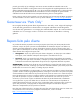
Cabling SAS cable routing Using the HP c-Class Blade SUV Cable The HP c-Class Blade SUV Cable enables the user to perform server blade administration, configuration, and diagnostic procedures by connecting video and USB devices directly to the server blade. For SUV cable connectors, see "HP c-Class Blade SUV Cable (on page 62).
Accessing a server blade with local KVM CAUTION: Before disconnecting the SUV cable from the connector, always squeeze the release buttons on the sides of the connector. Failure to do so can result in damage to the equipment. NOTE: For this configuration, a USB hub is not necessary. To connect additional devices, use a USB hub. 1. Connect the SUV cable to the server blade. 2. Connect the video connector to a monitor. 3. Connect a USB mouse to one USB connector. 4.
o USB CD/DVD-ROM drive o USB keyboard o USB mouse o USB diskette drive NOTE: Use a USB hub when connecting a USB diskette drive and/or USB CD-ROM drive to the server blade. The USB hub provides additional connections.
Diagnostic tools Troubleshooting resources The HP ProLiant Servers Troubleshooting Guide provides procedures for resolving common problems and comprehensive courses of action for fault isolation and identification, error message interpretation, issue resolution, and software maintenance on ProLiant servers and server blades. This guide includes problemspecific flowcharts to help you navigate complex troubleshooting processes. To view the guide, select a language: • English (http://www.hp.
This functionality supports operating systems that may not be supported by the server blade. For operating systems supported by the server blade, see the HP website (http://www.hp.com/go/supportos). If a significant change occurs between data-gathering intervals, the survey function marks the previous information and overwrites the survey data files to reflect the latest changes in the configuration.
Legacy USB support provides USB functionality in environments where USB support is normally not available. Specifically, HP provides legacy USB functionality for: • POST • RBSU • Diagnostics • DOS • Operating environments which do not provide native USB support For more information on ProLiant USB support, refer to the HP website (http://h18004.www1.hp.com/products/servers/platforms/usb-support.html).
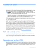
Component identification Front panel components Item Description 1 Hard drive bay 2 2 Server blade handle 3 Server blade handle release button 4 Serial pull tab 5 Hard drive bay 1 6 HP c-Class Blade SUV cable connector* 7 Power On/Standby button * The SUV connector and the HP c-Class Blade SUV Cable are for some server blade configuration and diagnostic procedures.
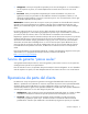
Front panel LEDs Item Description Status 1 UID LED Blue = Identified Blue flashing = Active remote management Off = No active remote management 2 Health LED Green = Normal operation Amber flashing = Degraded condition Red flashing = Critical condition 3 NIC 1 LED* Green = Network linked Green flashing = Network activity Off = No link or activity 4 NIC 2 LED* Green = Network linked Green flashing = Network activity Off = No link or activity 5 NIC 3 LED* Green = Network linked Green flashing
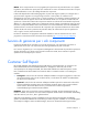
SAS and SATA hard drive LEDs Item Description 1 Fault/UID LED (amber/blue) 2 Online LED (green) SAS and SATA hard drive LED combinations Online/activity LED (green) Fault/UID LED (amber/blue) Interpretation On, off, or flashing Alternating amber and blue The drive has failed, or a predictive failure alert has been received for this drive; it also has been selected by a management application.
Online/activity LED (green) Fault/UID LED (amber/blue) Interpretation Flashing irregularly Amber, flashing regularly (1 Hz) The drive is active, but a predictive failure alert has been received for this drive. Replace the drive as soon as possible. Flashing irregularly Off The drive is active, and it is operating normally. Off Steadily amber A critical fault condition has been identified for this drive, and the controller has placed it offline. Replace the drive as soon as possible.
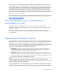
Item Description 13 Enclosure connector 2 14 System board thumbscrew 15 Embedded NIC 16 Embedded NIC 17 Smart Array E200i cache module (under mezzanine card 3) 18 SAS cable 19 Processor socket 1 (populated) 20 DIMM slots (Processor 1 memory banks A and B) 21 System battery 22 DIMM slots (Processor 3 memory banks E and F) 23 Processor socket 3 24 System board thumbscrew 25 System maintenance switch (SW2) 26 Hard drive backplane connector The symbols correspond to the symbols loc
System maintenance switch Position Function Default 1* iLO 2 security override Off 2 Configuration lock Off 3 Reserved Off 4 Reserved Off 5* Password disabled Off 6* Reset configuration Off 7 Reserved Off 8 Reserved Off *To access redundant ROM, set S1, S5, and S6 to ON.
Accessing the redundant ROM If the system ROM is not corrupted, use RBSU to switch to the redundant ROM. If the system ROM is corrupted, the system automatically switches to the redundant ROM in most cases. If the system does not automatically switch to the redundant ROM, perform the following steps: 1. Power down the server blade (on page 23). 2. Remove the server blade (on page 23). 3. Remove the access panel ("Access panel" on page 24). 4.
Specifications Environmental specifications Specification Value Temperature range* Operating 10°C to 35°C (50°F to 95°F) Shipping -40°C to 60°C (-40°F to 140°F) Storage -20°C to 60°C (-4°F to 140°F) Maximum wet bulb temperature 30°C (86°F) Relative humidity (noncondensing)** Operating 10% to 90% Shipping 10% to 90% Storage 10% to 95% * All temperature ratings shown are for sea level. An altitude derating of 1°C per 304.8 m (1.8°F per 1,000 ft) to 3048 m (10,000 ft) is applicable.
Acronyms and abbreviations ADU Array Diagnostics Utility CSR Customer Self Repair DIMM dual inline memory module ESD electrostatic discharge FC Fibre Channel HBA host bus adapter I/O input/output iLO 2 Integrated Lights-Out 2 IML Integrated Management Log LED light-emitting diode NIC network interface controller OS operating system Acronyms and abbreviations 64
PCI peripheral component interface PCIe peripheral component interconnect express RBSU ROM-Based Setup Utility ROM read-only memory SAS serial attached SCSI SATA serial ATA SFF small form-factor SIM Systems Insight Manager UID unit identification USB universal serial bus Acronyms and abbreviations 65
Index A access panel 24 ADU (Array Diagnostic Utility) 54 B battery 43 battery pack, removing 29 battery-backed write cache battery pack 29 buttons 56 C cables 50 cabling 50 cache module 28 cautions 21 component identification 56, 58, 59 components 16, 56, 59 connectors 56, 60 CSR (customer self repair) 5 D diagnostic tools 53 diagnostics utility 53 DIMM baffles 25 DIMM slots 60 DIMMs 26 E electrostatic discharge 21 F features 56 front panel components 56 front panel LEDs 57 front panel/hard drive cage
removing the server blade 23 ROM redundancy 62 S safety considerations 21 safety information 21 SAS cabling 29, 50 SAS drives 58 SAS hard drive LEDs 58 SAS/SATA LED combinations 58 SATA hard drive 58 SATA hard drive LEDs 58 server blade handle 32 specifications 63 specifications, environmental 63 static electricity 21 symbols on equipment 22 system battery 43 system board 44 system board battery 43 system board components 59 system maintenance switch 61 T tools 21, 53 troubleshooting 53 U USB connectors