
HP ProLiant DL120 Generation 5 Server Installation Sheet
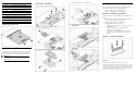

Table Of Contents
HP ProLiant DL120
Generation 5 Server
Installation Sheet
`
Configuring the server
1. Connect all peripherals to your ProLiant server.
o Keyboard
o Mouse
o Monitor
2. Determine the server BIOS version.
a. Power up the server.
b. Press the Esc key at the HP logo screen, and then press the
Pause key to halt screen movement.
c. Note the server BIOS version.
d. Verify the server BIOS version against the latest BIOS
version listed for this server on the HP website:
http://www.hp.com
.
e. If you do not have the latest BIOS, update the BIOS now.
f. Refer to the HP ProLiant DL120 Generation 5 Server
Maintenance and Service Guide available on the HP
website: http://www.hp.com.
Default boot priority
By default, the server searches for boot devices in the following
order:
1. Optical disc drive (DVD-ROM)
2. Removable drive
3. Hard disk drive
4. Embedded NIC
Server configuration guidelines
Read the following items before performing any of the installation
procedures described in later sections.
WARNING: Failure to properly turn off the system power
before you open the server or before you start removing
or installing hardware components may cause serious
damage as well as bodily harm.
WARNING: To reduce the risk of personal injury from
hot surfaces, allow the chassis and any installed
hardware component to cool before touching them.
CAUTION: Observe the ESD precautions, pre- and post-
installation procedures, and proper cabling management
described in Chapter 2 of the HP ProLiant DL120
Generation 5 Server Maintenance and Service Guide
when performing any installation procedure.
Getting additional documentation
Refer to the HP ProLiant DL120 Generation 5 Server Support CD for
additional information and updates not provided in this installation
sheet. You can also access additional information and
documentation from the HP website at http://www.hp.com/
, either
by connecting directly or through the Support CD.
Identifying server components
Front panel components
Item Component Item Component
1 Plastic serial No. Pull Tab
DL1U
8 Optical disc drive (ODD)
manual eject hole
2 Front USB ports 9 ODD eject button
3 Front unit identification
(UID) button/LED
10 ODD activity LED
4 System health LED 11 Optical disc drive
5 Embedded NIC
activity/link LED
12 Hard Disk Drive 2
6 HDD activity LED 13 Hard Disk Drive 1
7 Power/standby
button/LED
NOTE: The location/availability of items 8 – 10 may vary depending on
the model of the installed optical disc drive.
Rear panel components
Item Component Item Component
1 PSU cable socket 3 PS/2 mouse port
2 PS/2 keyboard port 4 Embedded NIC port
Item Component Item Component
5 Rear USB ports 10 Expansion slot 2 cover
6 Management NIC
(optional)
11 Expansion slot 1 cover
7 Serial port 12 System thumb screw
8 Video port 13 Embedded NIC link LED
9 Rear UID button/LED 14 Embedded NIC activity LED
System board components
Item Code Component
1 CN6 DL120 G5 HP Lights-Out 100c module
connector
2 DIMM_CH2_B Channel 2 1
st
DDR II DIMM slot
3 DIMM_CH2_D Channel 2 2
nd
DDR II DIMM slot
4 DIMM_CH1_A Channel 1 1
st
DDR II DIMM slot
5 DIMM_CH1_C Channel 1 2
nd
DDR II DIMM slot
6 CPU Processor
7 PWR_CN 20-pin ATX system board power connector
8 CN4 4-pin ATX processor power connector
9 CPU_FAN1 Processor fan 1 connector
10 CPU_FAN2 Processor fan 2 connector
11 LED1 Processor fan failure LED
12 JP5 BIOS boot block jumper
13 JP13 NMI jumper
14 LED3 System/processor over temperature (OTP) LED
15 CN8 Front panel board connector
16 CN26 SAS LED cable connector
17 SYSFAN System fan connector
18 LED2 System fan failure LED
19 CN9 Front USB port connector
20 SKT2 Internal USB connector
21 BAT1 System battery
22 HDD2 HDD 2 SATA cable connector
Part number: 466550-001
March 2008 (First edition)