HP ProLiant DL120 G6 Server User Guide Abstract This document is for the person who installs, administers, and troubleshoots servers and storage systems. HP assumes you are qualified in the servicing of computer equipment and trained in recognizing hazards in products with hazardous energy levels.
© Copyright 2009, 2012 Hewlett-Packard Development Company, L.P. The information contained herein is subject to change without notice. The only warranties for HP products and services are set forth in the express warranty statements accompanying such products and services. Nothing herein should be construed as constituting an additional warranty. HP shall not be liable for technical or editorial errors or omissions contained herein. Microsoft®, Windows®, and Windows Server® are U.S.
Contents Component identification ............................................................................................................... 6 Front panel components ................................................................................................................................ 6 Front panel LEDs and buttons ......................................................................................................................... 6 SAS and SATA device numbers .............................
Hard drive guidelines ....................................................................................................................... 26 Removing a hard drive blank ............................................................................................................ 27 Removing a hard drive ..................................................................................................................... 27 Installing a hot-plug hard drive ...................................................
Hardware problems ................................................................................................................................... 66 Power problems ............................................................................................................................... 67 General hardware problems ............................................................................................................. 68 Internal system problems .................................................
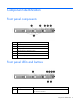
Component identification Front panel components Item Description 1 Optical drive 2 Serial label pull tab 3 USB ports (2) 4 Unit Identification (UID) button/LED 5 Power/standby button LED 6 Hard drive bays (4) Front panel LEDs and buttons Item Description Status 1 Optical drive LED On = Drive is in use. Off = Drive is not active.
Item Description Status 2 Internal health LED Green = System health is normal. Amber = System health is degraded. To identify the component in a degraded state, see "System board LEDs (on page 11)." Red = System health is critical. To identify the component in a critical state, see "System board LEDs (on page 11)." Off = System health is normal (when in standby mode). 3 NIC 1 link/activity LED Green = Network link exists. Flashing green = Network link and activity exist.
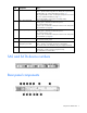
Item Description 1 Power cord connector 2 Mouse connector 3 10/100/1000 NIC 1 connector/shared Lights-Out 100 management port 4 10/100/1000 NIC 2 connector 5 Serial connector 6 Slot 1 PCIe2 x16 (4, 2, 1) 7 Slot 2 PCIe2 x16 (16, 8, 4, 1) 8 UID button/LED 9 Dedicated Lights-Out 100 management port 10 Video connector 11 USB connectors (2) 12 USB connectors (2) 13 Keyboard connector Rear panel LEDs and buttons Item Description Status 1 UID button/LED Blue = Identification Flash
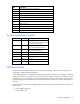
PCI expansion slot definitions Slot Type Length Connector Interconnect 1 PCIe2 Full x16 x16 1 Optional PCI-X Full 133 MHz/3.
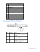
Item Description 18 Internal USB connector for tape device 19 BMC recovery jumper 20 BMC password reset jumper 21 Expansion slot 1 (for riser board) 22 Expansion slot 2 (for riser board) 23 System maintenance switch 24 Internal USB connector for STD USB 25 TPM connector 26 System battery 27 4-pin ATX processor power connector 28 Processor System maintenance switch Position Default Function S1 Off Off = Normal On = Clears the BIOS CMOS and rests the administrator password.
• Use the Lights-Out 100 Virtual NMI feature For additional information, see the whitepaper on the HP website (http://h20000.www2.hp.com/bc/docs/support/SupportManual/c00797875/c00797875.pdf). System board LEDs Item LED description Status 1 Processor fan failure Amber = Processor fan error Off = Normal 2 DIMM failure Amber = DIMM has failed or is missing. Off = Normal 3 Overtemperature Amber = System has reached a cautionary or critical temperature level.
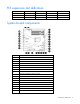
Fan locations Battery pack LEDs Item Color Description 1 Green System Power LED. This LED is on when the system is powered up and 12 V system power is available. This power supply is used to maintain the battery charge and provide supplementary power to the cache microcontroller. 2 Green Auxiliary Power LED. This LED is on when 3.3V auxiliary voltage is detected.
Item Color Description 3 Amber Battery Health LED. To interpret the illumination patterns of this LED, see the following table. 4 Green BBWC Status LED. To interpret the illumination patterns of this LED, see the following table. LED3 pattern LED4 pattern Interpretation Off Flashing (2 Hz) The system is powered down, and the cache contains data that has not yet been written to the drives. Restore system power as soon as possible to prevent data loss.
FBWC module LEDs The FBWC module has two single-color LEDs (green and amber). The LEDs are duplicated on the reverse side of the cache module to facilitate status viewing. 1 Green LED 2 Amber LED Interpretation Off On A backup is in progress. Flashing (1 Hz) On A restore is in progress. Flashing (1 Hz) Off The capacitor pack is charging. On Off The capacitor pack has completed charging.
Operations Power up the server To power up the server, press the Power On/Standby button. Power down the server WARNING: To reduce the risk of personal injury, electric shock, or damage to the equipment, remove the power cord to remove power from the server. The front panel Power On/Standby button does not completely shut off system power. Portions of the power supply and some internal circuitry remain active until AC power is removed.
5. Place the server on a sturdy, level surface. Remove the access panel WARNING: To reduce the risk of personal injury from hot surfaces, allow the drives and the internal system components to cool before touching them. CAUTION: Do not operate the server for long periods with the access panel open or removed. Operating the server in this manner results in improper airflow and improper cooling that can lead to thermal damage. To remove the component: 1. Power down the server (on page 15). 2.
CAUTION: To prevent damage to the server or expansion boards, power down the server and remove all AC power cords before removing or installing the PCI riser board assembly. 1. Power down the server (on page 15). 2. Remove the server from the rack (on page 15). 3. Remove the access panel (on page 16). 4. Disconnect all internal cables connected to existing expansion boards. 5. Remove the PCI riser board assembly: a. Remove the T-10 screw. b. Remove the T-15 screws. c.
1. Install the PCI riser board assembly. 2. Connect any internal cables for expansion boards. 3. Install the access panel. 4. Install the server into the rack.
Setup Optional installation services Delivered by experienced, certified engineers, HP Care Pack services help you keep your servers up and running with support packages tailored specifically for HP ProLiant systems. HP Care Packs let you integrate both hardware and software support into a single package. A number of service level options are available to meet your needs.
In a tower configuration, leave at least a 7.6-cm (3-in) clearance space at the front and back of the server for proper ventilation. Rack server To allow for servicing and adequate airflow, observe the following space and airflow requirements when deciding where to install a rack: • Leave a minimum clearance of 63.5 cm (25 in) in front of the rack. • Leave a minimum clearance of 76.2 cm (30 in) behind the rack. • Leave a minimum clearance of 121.
CAUTION: To reduce the risk of damage to the equipment when installing third-party options: • Do not permit optional equipment to impede airflow around the server or to increase the internal rack temperature beyond the maximum allowable limits. • Do not exceed the manufacturer’s TMRA. Power requirements Installation of this equipment must comply with local and regional electrical regulations governing the installation of information technology equipment by licensed electricians.
Rack warnings WARNING: To reduce the risk of personal injury or damage to the equipment, be sure that: • • • • • The leveling jacks are extended to the floor. The full weight of the rack rests on the leveling jacks. The stabilizing feet are attached to the rack if it is a single-rack installation. The racks are coupled together in multiple-rack installations. Only one component is extended at a time. A rack may become unstable if more than one component is extended for any reason.
Hardware options installation Introduction If more than one option is being installed, read the installation instructions for all the hardware options and identify similar steps to streamline the installation process. WARNING: To reduce the risk of personal injury from hot surfaces, allow the drives and the internal system components to cool before touching them. CAUTION: To prevent damage to electrical components, properly ground the server before beginning any installation procedure.
DIMM slots in this server are identified by number and by letter. Letters identify the slots to populate for specific AMP modes. Slot numbers are reported by ROM messages during boot and for error reporting. Single-, dual-, and quad-rank DIMMs To understand and configure memory protection modes properly, an understanding of single-, dual-, and quad-rank DIMMs is helpful. Some DIMM configuration requirements are based on these classifications.
Item Description Definition 4 Memory speed 10600 = 1333-MHz 8500 = 1066-MHz 5 DIMM type R = RDIMM (registered) E = UDIMM (unbuffered with ECC) For the latest supported memory information, see the QuickSpecs on the HP website (http://www.hp.com). General DIMM slot population guidelines • The HP ProLiant DL120 G6 Server has six memory slots. • There are two channels per server with three DIMM slot per channel.
Installing DIMMs CAUTION: To avoid damage to the hard drives, memory, and other system components, the air baffle, drive blanks, and access panel must be installed when the server is powered up. 1. Power down the server (on page 15). 2. Remove the server from the rack (on page 15). 3. Remove the access panel (on page 16). 4. Remove the air baffle (on page 16). For more information, see the server installation sheet on the HP website (http://www.hp.com/go/bizsupport). 5. Open the DIMM slot latches.
Optional storage controllers provide support for hot-plug capability and drive LEDs. Controller options are: • The embedded controller supports non-hot-plug SATA hard drives. Drive LEDs are not supported. • Optional SATA controllers support hot-plug SATA hard drives and drive LEDs. • Optional SAS controllers support hot-plug SAS or SATA hard drives and drive LEDs.
3. Remove the hard drive. Installing a hot-plug hard drive IMPORTANT: Hot-plug capability and drive LED support are only available when a supported optional controller is installed in the server. 1. Power down the server (on page 15). 2. Remove the existing hard drive blank ("Removing a hard drive blank" on page 27). 3. Prepare the hard drive.
4. Install the hard drive. Installing a non-hot-plug hard drive The server supports up to four SATA hard drives with the embedded controller. The server supports up to four SAS hard drives with the following options: • Optional SAS controller • Optional SAS controller cable • Optional SAS hard drive LED cable ("SAS hard drive LED cable option" on page 37) (for LED functionality) For optimal performance, do not mix SAS and SATA hard drives.
4. Using a T-10 Torx screwdriver, remove the hard drive carrier. 5. Remove four T-10 screws from the hard drive carrier. 6. Install the hard drive.
7. Install the hard drive assembly. 8. Route and connect the hard drive data and power cables to the hard drive. For SAS and SATA device numbers, see the server installation sheet.
o 9. SAS hard drive Connect the hard drive data cables: o For SATA hard drives, connect the cable to the system board. For more information, see the server installation sheet. o For SAS hard drives, connect the optional SAS/SATA controller cable to the optional SAS controller. 10. Install the access panel. 11. Install the server in the rack. Resume normal server operations.
Optical drive option To install the component: 1. Power down the server (on page 15). 2. Remove the server from the rack (on page 15). 3. Remove the access panel (on page 16). 4. Remove the air baffle (on page 16). 5. Remove the 9.5-mm optical drive blank. Retain the blank for future use. 6. Install the 9.5-mm optical drive assembly. When fully inserted, the assembly locking latch clicks.
7. Using a T-15 screwdriver, secure the drive to the chassis. 8. Connect the optical drive and power cable to the optical drive. 9. Connect the power connector to the power supply backplane. 10. Install the access panel. 11. Install the server into the rack. Expansion board option To install the component: 1. Power down the server (on page 15). 2. Remove the server from the rack (on page 15). 3. Remove the access panel (on page 16). 4.
5. Remove the PCI riser board assembly (on page 16). 6. Remove the expansion slot covers. 7. Install the expansion board. IMPORTANT: The server does not power up if the PCI riser board assembly is not seated properly. 8. Install the PCI riser board assembly (on page 17). 9. Connect all internal cables for expansion boards. 10. Install the access panel. 11. Install the server into the rack.
PCI-X riser board option To install the component: 1. Power down the server (on page 15). 2. Remove the server from the rack (on page 15). 3. Remove the access panel (on page 16). 4. Disconnect all internal cables connected to existing expansion boards. 5. Remove the PCI riser board assembly (on page 16). 6. Remove all installed expansion boards. 7. Remove the PCIe riser board from the assembly. 8. Install the optional PCI-X riser board. 9.
11. Connect all internal cables for expansion boards. 12. Install the access panel. 13. Install the server into the rack. Storage controller option IMPORTANT: For additional installation and configuration information, refer to the documentation that ships with the option. To install the component: 1. Power down the server (on page 15). 2. Remove the server from the rack (on page 15). 3. Remove the access panel (on page 16). 4. Remove the PCI riser board assembly (on page 16). 5.
5. Connect the SAS hard drive LED cable to the system board and to the SAS controller. 6. Install the access panel. 7. Install the server into the rack. Battery-backed write cache battery pack option CAUTION: To prevent a server malfunction or damage to the equipment, do not add or remove the battery pack while an array capacity expansion, RAID level migration, or stripe size migration is in progress.
5. Install the cache module on the controller. 6. Connect the cable to the cache module.
7. Install the battery pack. 8. Route the cable. 9. Install the access panel. 10. Install the server into the rack. Installing the FBWC module and capacitor pack To install the component: CAUTION: The cache module connector does not use the industry standard DDR3 mini DIMM pinout. Do not use this controller with cache modules designed for other controller models, because the controller can malfunction and you can lose data.
7. Connect the capacitor pack cable to the connector on the top of the cache module. 8. Install the cache module. 9. Install the capacitor pack.
10. Route the cable. 11. Install the access panel. 12. Install the server into the rack. 13. Power up the server (on page 15). HP Trusted Platform Module option Use these instructions to install and enable a TPM on a supported server. This procedure includes three sections: 1. Installing the Trusted Platform Module board (on page 42). 2. Retaining the recovery key/password (on page 44). 3. Enabling the Trusted Platform Module (on page 44).
1. Power down the server (on page 15). 2. Remove the server from the rack, if necessary ("Remove the server from the rack" on page 15). 3. Place the server on a flat, level work surface. 4. Remove the access panel (on page 16). 5. Access the TPM connector. See the server-specific installation sheet. CAUTION: Any attempt to remove an installed TPM from the system board breaks or disfigures the TPM security rivet.
11. Power up the server (on page 15). Retaining the recovery key/password The recovery key/password is generated during BitLocker™ setup, and can be saved and printed after BitLocker™ is enabled. When using BitLocker™, always retain the recovery key/password. The recovery key/password is required to enter Recovery Mode after BitLocker™ detects a possible compromise of system integrity.
Cabling Cabling overview This section provides guidelines that help you make informed decisions about cabling the server and hardware options to optimize performance. Server cabling CAUTION: When routing cables, always be sure that the cables are not in a position where they can be pinched or air flow can be blocked. IMPORTANT: Route the cables without blocking the airflow or other installed components. Use the cable clips installed in the chassis to manage cable routing.
BBWC battery cabling to an optional controller Power supply (500 W) cabling Cabling 46
SATA cabling SATA cabling to the SGPIO connector and the 12C cable connector Cabling 47
SAS cabling to the SGPIO connector and the 12C cable connector Internal USB cabling Cabling 48
Fan cabling Cabling 49
Software and configuration utilities BIOS Setup Utility To use the BIOS Setup Utility, use the following keys: • To access the BIOS Setup Utility, press the F10 key during power-up when prompted. • To navigate the menu system, use the arrow keys. • To make selections, press the + or - key. • To access Help for a highlighted configuration option, press the F1 key. • To save settings, select Exit>Save Settings.
By default, the auto-configuration process configures the system for the English language. To change any default settings in the auto-configuration process (such as the settings for language, operating system, and primary boot controller), execute the BIOS Setup Utility (on page 50) by pressing the F10 key during power-up when prompted. After the settings are selected, exit the BIOS Setup Utility and allow the server to reboot automatically.
• Displaying system information • Selecting the primary boot controller • Configuring memory options • Language selection For more information on RBSU, see the HP ROM-Based Setup Utility User Guide on the Documentation CD or the HP website (http://www.hp.com/support/smartstart/documentation). Re-entering the server serial number After you replace the system board, you must re-enter the server serial number. Re-enter the server serial number using the Setsys Utility.
Troubleshooting Common problem resolution Loose connections (on page 53) Service notifications (on page 53) Firmware updates (on page 53) DIMM handling guidelines (on page 54) SAS and SATA hard drive guidelines (on page 54) Loose connections CAUTION: If you are using a Virtual Connect environment, some of these procedures might cause the loss of Virtual Connect credentials and the loss of communication between the Onboard Administrator and the Virtual Connect Interconnect module.
o The HP website (http://www.hp.com/support) • The most recent version of a particular server or option firmware from the HP website (http://www.hp.com/support) • Components for option firmware updates available from the HP website (http://www.hp.com/support) HP offers a subscription service that can provide notification of firmware updates. For more information, see "Subscriber's Choice (on page 52)." For more information on updating firmware, see "Firmware maintenance (on page 86).
Problem diagnosis This section covers the steps to take in order to diagnose a problem quickly. To effectively troubleshoot a problem, HP recommends that you start with the first flowchart in this section, "Start diagnosis flowchart (on page 58)," and follow the appropriate diagnostic path. If the other flowcharts do not provide a troubleshooting solution, follow the diagnostic steps in "General diagnosis flowchart (on page 59).
49-109 kg 100-240 lb This symbol indicates that the component exceeds the recommended weight for one individual to handle safely. WARNING: To reduce the risk of personal injury or damage to the equipment, observe local occupational health and safety requirements and guidelines for manual material handling. These symbols, on power supplies or systems, indicate that the equipment is supplied by multiple sources of power.
CAUTION: The server is designed to be electrically grounded (earthed). To ensure proper operation, plug the AC power cord into a properly grounded AC outlet only. Preparing the server for diagnosis 1. Be sure the server is in the proper operating environment with adequate power, air conditioning, and humidity control. Refer to the server documentation for required environmental conditions. 2. Record any error messages displayed by the system. 3. Remove all diskettes and CDs from the media drives. 4.
The available flowcharts include: • Start diagnosis flowchart (on page 58) • General diagnosis flowchart (on page 59) • Power-on problems flowchart (on page 61) • POST problems flowchart (on page 62) • OS boot problems flowchart (on page 64) • Server fault indications flowchart (on page 65) The number contained in parentheses in the flowchart boxes corresponds to a table with references to other detailed documents or troubleshooting instructions.
General diagnosis flowchart The General Diagnosis flowchart provides a generic approach to troubleshooting. If you are unsure of the problem, or if the other flowcharts do not correct the problem, use the following flowchart. Item See 1 "Symptom information (on page 57)" 2 "Loose connections (on page 53)" 3 "Service notifications (on page 53)" 4 The most recent version of a particular server or option firmware is available on the HP website (http://www.hp.com/support).
Item See 7 • • Server maintenance and service guide, located on the Easy Set-up CD or the HP website (http://www.hp.
Power-on problems flowchart Symptoms: • The server does not power on. • The system power LED is off or amber. NOTE: For the location of server LEDs and information on their statuses, refer to the server documentation.
POST problems flowchart Symptoms: • Server does not complete POST NOTE: The server has completed POST when the system attempts to access the boot device.
Item See 1 Server maintenance and service guide, located on the Easy Set-up CD or the HP website (http://www.hp.com/products/servers/platforms) 2 "Loose connections (on page 53)" 3 "General memory problems are occurring (on page 75)" 4 • • 5 "Symptom information (on page 57)" 6 • • 7 "HP contact information (on page 99)" "Hardware problems (on page 66)" Server maintenance and service guide, located on the Easy Set-up CD or the HP website (http://www.hp.
OS boot problems flowchart Symptom: Server does not boot a previously installed operating system.
Server fault indications flowchart Symptom: Server boots, but the internal health LED or external health LED is red or amber. NOTE: For the location of server LEDs and information on their statuses, refer to the server documentation.
Item See 1 Server maintenance and service guide, located on the Easy Set-up CD or the HP website (http://www.hp.com/products/servers/platforms) 2 "Power-on problems flowchart (on page 61)" 3 "HP Insight Diagnostics (on page 51)" 4 • • 5 "HP contact information (on page 99)" "Hardware problems (on page 66)" Server maintenance and service guide, located on the Easy Set-up CD or the HP website (http://www.hp.
General hardware problems (on page 68) Internal system problems (on page 71) External device problems (on page 78) System open circuits and short circuits (on page 77) Power problems Power source problems (on page 67) Power supply problems (on page 67) UPS problems (on page 68) Power source problems Action: 1. Press the Power On/Standby button to be sure it is on. If the server has a Power On/Standby button that returns to its original position after being pressed, be sure you press the switch firmly.
UPS problems UPS is not working properly Action: 1. Be sure the UPS batteries are charged to the proper level for operation. See the UPS documentation for details. 2. Be sure the UPS power switch is in the On position. See the UPS documentation for the location of the switch. 3. Be sure the UPS software is updated to the latest version. Use the Power Management software located on the Power Management CD. 4.
Problems with new hardware Action: 1. Refer to the server documentation to be sure the hardware being installed is a supported option on the server. Remove unsupported hardware. 2. Refer to the release notes included with the hardware to be sure the problem is not caused by a last minute change to the hardware release. If no documentation is available, refer to the HP support website (http://www.hp.com/support). 3. Be sure the new hardware is installed properly.
3. Reconnect power, and then power the system on. o If the video does not work, refer to "Video problems (on page 78)." CAUTION: Only authorized technicians trained by HP should attempt to remove the system board. If you believe the system board requires replacement, contact HP Technical Support ("HP contact information" on page 99) before proceeding. o If the system fails in this minimum configuration, one of the primary components has failed.
Internal system problems CD-ROM and DVD drive problems System does not boot from the drive Action: 1. Be sure the drive boot order is set so that the server boots from the CD-ROM drive first. 2. If the CD-ROM drive jumpers are set to CS (the factory default), be sure the CD-ROM drive is installed as device 0 on the cable so that it is in position for the server to boot from the drive. 3. Be sure no loose connections (on page 53) exist. 4.
DAT drives require cleaning every 8 to 25 hours of use or they may fail intermittently when using marginal or bad media. Be sure you are following the proper cleaning procedures described in the device and server documentation. NOTE: New DAT tapes may contain debris that will contaminate the DAT drive read/write head. If using new tapes for backup, clean the DAT drive frequently.
• Be sure the power and signal cable connectors are not damaged. • If the drive is connected to a nonembedded controller, be sure the controller is properly seated. DLT drive does not read tape Action: • Be sure the drive is seated. • Be sure the drive is installed properly. • Check each tape cartridge that has been used in the drive to see if a leader was dropped. After you locate any bad cartridges, dispose of them.
3. Be sure no ventilation problems exist. If you have been operating the server for an extended period of time with the access panel removed, airflow may have been impeded, causing thermal damage to components. Refer to the server documentation for further requirements. 4. Be sure no POST error messages are displayed while booting the server that indicate temperature violation or fan failure information. Refer to the server documentation for the temperature requirements for the server. 5.
3. When a TPM is installed and is being used with BitLocker™, be sure the TPM is enabled in RBSU ("HP ROM-Based Setup Utility" on page 51). See the TPM replacement recovery procedure in the operating system documentation. 4. When migrating encrypted data to a new server, be sure to follow the recovery procedures in the operating system documentation. Server response time is slower than usual Action: Be sure the hard drive is not full, and increase the amount of free space on the hard drive, if needed.
3. Be sure a memory count error ("Memory count error exists" on page 76) did not occur. Refer to the message displaying memory count during POST. Memory count error exists Possible Cause: The memory modules are not installed correctly. Action: 1. Be sure the memory modules are supported by the server. See the server documentation. 2. Be sure the memory modules have been installed correctly in a supported configuration. See the server documentation. 3.
4. Be sure you are not mixing processor stepping, core speeds, or cache sizes if this is not supported on the server. Refer to the server documentation for more information. CAUTION: Removal of some processors and heatsinks require special considerations for replacement, while other processors and heatsinks are integrated and cannot be reused once separated.
If you cannot determine the problem by checking the specific area, perform each of the following actions. Restart the server after each action to see if the problem has been corrected. • Reseat all I/O expansion boards. • Be sure no loose connections (on page 53) exist in the rest of the server, particularly with the cables that connect to the system board. • Be sure no foreign material exists, such as screws, bits, or slot bracket blanks, that may be short circuiting components.
8. Press any key, or type the password, and wait a few moments for the screen to activate to be sure the power-on password feature is not in effect. You can also tell if the power-on password is enabled if a key symbol is displayed on the screen when POST completes. If you do not have access to the password, you must disable the power-on password by using the Password Disable switch on the system board. Refer to the server documentation. 9.
o For tower model servers, check the cable connection from the input device to the server. 2. If a KVM switching device is in use, be sure all cables and connectors are the proper length and are supported by the switch. Refer to the switch documentation. 3. Be sure the current drivers for the operating system are installed. 4. Be sure the device driver is not corrupted by replacing the driver. 5. Restart the system and check whether the input device functions correctly after the server restarts.
4. Be sure you are in terminal mode and not MS-DOS mode. 5. Refer to the HP website (http://www.hp.com) for a complete list of AT commands. AT commands are not visible Action: Set the echo command to On using the AT command ATE. Data is displayed as garbled characters after the connection is established Action: 1. Be sure both modems have the same settings, including speed, data, parity, and stop bits. 2. Be sure the software is set for the correct terminal emulation. a.
2. If the line you are accessing requires error control to be turned off, do so using the AT command AT&Q6%C0. 3. Be sure no line interference exists. Retry the connection by dialing the number several times. If conditions remain poor, contact the telephone company to have the line tested. 4. Be sure the modem is current and compliant with CCITT and Bell standards. Replace with a supported modem if needed. You are unable to connect to an online subscription service Action: 1.
Network controller has stopped working Action: 1. Check the network controller LEDs to see if any statuses indicate the source of the problem. For LED information, refer to the network controller documentation. 2. Be sure the correct network driver is installed for the controller and that the driver file is not corrupted. Reinstall the driver. 3. Be sure no loose connections (on page 53) exist. 4. Be sure the network cable is working by replacing it with a known functional cable. 5.
IMPORTANT: This guide provides information for multiple servers. Some information may not apply to the server you are troubleshooting. Refer to the server documentation for information on procedures, hardware options, software tools, and operating systems supported by the server. Refer to "Server software and configuration utilities ("Software and configuration utilities" on page 50)" for more information.
2. Be sure the server has adequate resources (processor speed, hard drive space, and memory) for the software. 3. Be sure the server ROM is current and the configuration is correct. 4. Be sure you have printed records of all troubleshooting information you have collected to this point. 5. Be sure you have two good backups before you start. Test the backups using a backup utility. 6. Check the operating system and application software resources to be sure you have the latest information. 7.
• Check the application log and operating system log for entries indicating why the software failed. • Check system settings to determine if they are the cause of the error. You may need to obtain the settings from the server setup utility and manually set the software switches. Refer to the application documentation, the vendor website, or both. • Check for overwritten files. Refer to the application documentation to find out which files are added by the application. • Reinstall the application.
This procedure is most effective when flashing the ROM on a small number of servers located in close proximity. To flash the ROM using ROMPaq: 1. Download the system ROMPaq utility diskette or USB drive key for each target server. ROMPaq downloads are available on the HP website (http://www.hp.com/support). 2. Shut down each target server, and then reboot using the correct ROMPaq diskette or USB drive key for that server. 3.
Contacting HP Contacting HP technical support or an authorized reseller (on page 88) Server information you need (on page 88) Operating system information you need (on page 89) Contacting HP technical support or an authorized reseller Before contacting HP, always attempt to resolve problems by completing the procedures in this guide.
• Any notes describing the details of the problem, including recent changes to the system, the events that triggered or are associated with the problem, and the steps needed to reproduce the problem. • Notes on anything nonstandard about the server setup. • Operating system information ("Operating system information you need" on page 89) Operating system information you need Depending on the problem, you may be asked for certain pieces of information.
• • o lspci -v o uname -a o cat /proc/meminfo o cat /proc/cpuinfo o rpm -ga o dmesg o lsmod o ps -ef o ifconfig -a o chkconfig -list o mount Contents of the following files: o /var/log/messages o /etc/modules.conf or etc/conf.modules o /etc/lilo.conf or /etc/grub.
Battery If the server no longer automatically displays the correct date and time, you may need to replace the battery that provides power to the real-time clock. Under normal use, battery life is 5 to 10 years. WARNING: The computer contains an internal lithium manganese dioxide, a vanadium pentoxide, or an alkaline battery pack. A risk of fire and burns exists if the battery pack is not properly handled. To reduce the risk of personal injury: • • • • Do not attempt to recharge the battery.
Regulatory compliance notices Regulatory compliance identification numbers For the purpose of regulatory compliance certifications and identification, this product has been assigned a unique regulatory model number. The regulatory model number can be found on the product nameplate label, along with all required approval markings and information. When requesting compliance information for this product, always refer to this regulatory model number.
radio communications. However, there is no guarantee that interference will not occur in a particular installation. If this equipment does cause harmful interference to radio or television reception, which can be determined by turning the equipment off and on, the user is encouraged to try to correct the interference by one or more of the following measures: • Reorient or relocate the receiving antenna. • Increase the separation between the equipment and receiver.
This Class A digital apparatus meets all requirements of the Canadian Interference-Causing Equipment Regulations. Cet appareil numérique de la classe A respecte toutes les exigences du Règlement sur le matériel brouilleur du Canada. Class B equipment This Class B digital apparatus meets all requirements of the Canadian Interference-Causing Equipment Regulations. Cet appareil numérique de la classe B respecte toutes les exigences du Règlement sur le matériel brouilleur du Canada.
This symbol on the product or on its packaging indicates that this product must not be disposed of with your other household waste. Instead, it is your responsibility to dispose of your waste equipment by handing it over to a designated collection point for the recycling of waste electrical and electronic equipment.
Class B equipment Laser compliance This product may be provided with an optical storage device (that is, CD or DVD drive) and/or fiber optic transceiver. Each of these devices contains a laser that is classified as a Class 1 Laser Product in accordance with US FDA regulations and the IEC 60825-1. The product does not emit hazardous laser radiation. Each laser product complies with 21 CFR 1040.10 and 1040.11 except for deviations pursuant to Laser Notice No.
Power cord statement for Japan Acoustics statement for Germany (Geräuschemission) Schalldruckpegel LpA < 70 dB(A) Zuschauerpositionen (bystander positions), Normaler Betrieb (normal operation) Nach ISO 7779:1999 (Typprüfung) Regulatory compliance notices 97
Electrostatic discharge Preventing electrostatic discharge To prevent damaging the system, be aware of the precautions you need to follow when setting up the system or handling parts. A discharge of static electricity from a finger or other conductor may damage system boards or other static-sensitive devices. This type of damage may reduce the life expectancy of the device. To prevent electrostatic damage: • Avoid hand contact by transporting and storing products in static-safe containers.
Technical support HP contact information For United States and worldwide contact information, see the Contact HP website (http://www.hp.com/go/assistance). In the United States: • To contact HP by phone, call 1-800-334-5144. For continuous quality improvement, calls may be recorded or monitored. • If you have purchased a Care Pack (service upgrade), see the Support & Drivers website (http://www8.hp.com/us/en/support-drivers.html). If the problem cannot be resolved at the website, call 1-800-633-3600.
providers or service partners) identifies that the repair can be accomplished by the use of a CSR part, HP will ship that part directly to you for replacement. There are two categories of CSR parts: • Mandatory—Parts for which customer self repair is mandatory. If you request HP to replace these parts, you will be charged for the travel and labor costs of this service. • Optional—Parts for which customer self repair is optional. These parts are also designed for customer self repair.
Pour plus d'informations sur le programme CSR de HP, contactez votre Mainteneur Agrée local. Pour plus d'informations sur ce programme en Amérique du Nord, consultez le site Web HP (http://www.hp.com/go/selfrepair). Riparazione da parte del cliente Per abbreviare i tempi di riparazione e garantire una maggiore flessibilità nella sostituzione di parti difettose, i prodotti HP sono realizzati con numerosi componenti che possono essere riparati direttamente dal cliente (CSR, Customer Self Repair).
HINWEIS: Einige Teile sind nicht für Customer Self Repair ausgelegt. Um den Garantieanspruch des Kunden zu erfüllen, muss das Teil von einem HP Servicepartner ersetzt werden. Im illustrierten Teilekatalog sind diese Teile mit „No“ bzw. „Nein“ gekennzeichnet. CSR-Teile werden abhängig von der Verfügbarkeit und vom Lieferziel am folgenden Geschäftstag geliefert. Für bestimmte Standorte ist eine Lieferung am selben Tag oder innerhalb von vier Stunden gegen einen Aufpreis verfügbar.
sustituciones que lleve a cabo el cliente, HP se hará cargo de todos los gastos de envío y devolución de componentes y escogerá la empresa de transporte que se utilice para dicho servicio. Para obtener más información acerca del programa de Reparaciones del propio cliente de HP, póngase en contacto con su proveedor de servicios local. Si está interesado en el programa para Norteamérica, visite la página web de HP siguiente (http://www.hp.com/go/selfrepair).
Opcional – Peças cujo reparo feito pelo cliente é opcional. Essas peças também são projetadas para o reparo feito pelo cliente. No entanto, se desejar que a HP as substitua, pode haver ou não a cobrança de taxa adicional, dependendo do tipo de serviço de garantia destinado ao produto. OBSERVAÇÃO: Algumas peças da HP não são projetadas para o reparo feito pelo cliente. A fim de cumprir a garantia do cliente, a HP exige que um técnico autorizado substitua a peça.
Technical support 105
Technical support 106
Acronyms and abbreviations ACU Array Configuration Utility AMP Advanced Memory Protection ATX advanced technology extended BBWC battery-backed write cache BIOS Basic Input/Output System BMC baseboard management controller DAT digital audio tape DDR double data rate DIMM dual inline memory module DLT digital linear tape FBWC flash-backed write cache IEC International Electrotechnical Commission Acronyms and abbreviations 107
KVM keyboard, video, and mouse LO100i HP Lights-Out 100 Remote Management processors NMI non-maskable interrupt NVRAM non-volatile memory ORCA Option ROM Configuration for Arrays PCI Express Peripheral Component Interconnect Express PCIe peripheral component interconnect express PCI-X peripheral component interconnect extended PDU power distribution unit POST Power-On Self Test PPM processor power module RDIMM Registered Dual In-line Memory Module SAS serial attached SCSI SATA serial ATA Acron
SGPIO serial general input/output STD standard USB TMRA recommended ambient operating temperature TPM trusted platform module UDIMM Unregistered Dual In-Line Memory Module UID unit identification USB universal serial bus Acronyms and abbreviations 109
Documentation feedback HP is committed to providing documentation that meets your needs. To help us improve the documentation, send any errors, suggestions, or comments to Documentation Feedback (mailto:docsfeedback@hp.com). Include the document title and part number, version number, or the URL when submitting your feedback.
Index A D access panel 16 acoustics statement for Germany 97 air baffle 16 airflow requirements 20 audio 79 authorized reseller 88, 99 authorized technician 56 auto-configuration process 50 DAT drives 72 data recovery 71, 74 Declaration of Conformity 93 diagnosing problems 53, 57 Diagnostic Adapter 80 diagnostic steps 57 diagnostic tools 51 DIMM installation guidelines 25 DIMM population guidelines 25 DIMM slots 25 DIMMs 24, 25, 54 DIMMs, installation 26 disposal, waste 94 documentation 110 downloading f
firmware, updating 53 firmware, upgrading 53 firmware, version 72, 87 flash ROM 86 front panel buttons 6 front panel components 6 front panel LEDs 6 G grounding methods 98 grounding requirements 21 H hard drive blanks 27 hard drive, removing 27 hard drive, replacing 28 hard drives, adding 29 hard drives, installing 23, 28 hard drives, moving 74, 75 hardware options 23 hardware options installation 22, 23 hardware problems 66, 68 hardware troubleshooting 69 health LEDs 10 help resources 99 HP Insight Diagn
PPM slots 77 preparation procedures 15 preparing the server for diagnosis 57 problem diagnosis 53, 55, 57 processors 76 R rack installation 22 rack resources 19 rack stability 56 RBSU (ROM-Based Setup Utility) 51 rear panel buttons 8 rear panel LEDs 8 Re-entering the server serial number 52 registering the server 22 regulatory compliance notices 92, 94 removing server from rack 15 required information 89, 99 resetting the system 10, 52 restoring 84 ROM-Based Setup Utility (RBSU) 51 ROMPaq utility 51, 86 S