
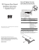
PCI Express Riser Board Installation Instructions ProLiant DL100 Series Generation 2 Servers
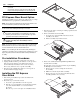

Item Component
1 Standard height/full-length 64-bit/133 MHz PCI-X
riser board
Users have the option to replace this riser board with a PCI
Express model using the PCI Express riser board option kit.
2 Low profile 64-bit/133 MHz PCI-X riser board
PCI Express Riser Board Option
Installing the PCI Express riser board option allows the use of high
bandwidth-intensive peripherals in your ProLiant server.
NOTE: The procedures described in this document assume that the server
is out of the rack and is positioned on a flat, stable surface.
IMPORTANT: Observe the pre- and post-installation procedures described
in later sections when installing the PCI Express riser board.
CAUTION: When handling the riser boards, follow the ESD
precautions listed in Chapter 2 of the Maintenance and Service
Guide of your ProLiant server. You can download a copy of this
guide from the HP website at http://www.hp.com/.
WARNING: Failure to properly turn off the server before you
open the server may cause serious damage as well as
bodily harm.
NOTE: This document applies to several server models in the HP ProLiant
DL100 Generation 2 server series. The illustrative figures used here may
not be an exact match to the user’s actual ProLiant server.
NOTE: For ease of reading, the PCI riser board assembly will simply be
referred to as “assembly” in the succeeding sections. Furthermore, in some
figures, the plane section of the PCI riser board assembly is dimmed out
for clarity.
Pre-installation Procedures
1. Turn off the server and all the peripherals connected to it.
2. Unplug all cables from the power outlets to avoid exposure to
high energy levels that may cause burns when parts are
short-circuited by metal objects such as tools or jewelry.
If necessary, label each one to expedite reassembly.
3. Disconnect telecommunication cables to avoid exposure to
shock hazard from ringing voltages.
Installing the PCI Express
Riser Board
1. Perform the pre-installation procedures described in the
previous section.
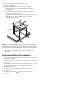
2. Detach the top cover from the chassis:
a. Loosen the captive thumbscrew on the rear panel.
b. Slide the cover approximately 1.25 cm (0.5 in) toward the
rear of the unit, then lift the cover to detach it from
the chassis.
Place the top cover in a safe place for reinstallation later.
3. Disconnect any cables connecting an existing expansion board
to the system board.
4. Remove the
PCI riser board assembly:
a. Loosen the two captive thumbscrews that secure the
assembly to the chassis.
b. Lift the assembly away from the chassis.
5. Remove the default standard height/full-length PCI-X riser
board from the assembly:
Keep the three screws you removed in this step for installing
the PCI Express riser board later.
a. Remove the two screws securing the riser board to
the assembly.
b. Pull the riser board away from the assembly.
c. Remove the spare screw located on the third tab of the
assembly (from the slot cover side).