HP ProLiant DL140 Generation 2 Server Maintenance and Service Guide Part number: 381737-004 Fourth edition: September 2006
Legal notices © Copyright 2006 Hewlett-Packard Development Company, L.P. The information contained herein is subject to change without notice. The only warranties for HP products and services are set forth in the express warranty statements accompanying such products and services. Nothing herein should be construed as constituting an additional warranty. HP shall not be liable for technical or editorial errors or omissions contained herein. Intel and Xeon are US registered trademarks of Intel Corporation.
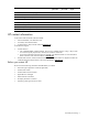
Contents Illustrated parts catalog Customer Self Repair (CSR) ....................................................................................................................... 5 Mechanical parts exploded view ............................................................................................................... 6 System components exploded view ............................................................................................................ 7 HP contact information ................
System specifications Technical specifications .......................................................................................................................... 65 System unit....................................................................................................................................... 65 Memory........................................................................................................................................... 66 Processor .............................
Illustrated parts catalog Customer Self Repair (CSR) What is customer self repair? HP's customer self-repair program offers you the fastest service under either warranty or contract. It enables HP to ship replacement parts directly to you so that you can replace them. Using this program, you can replace parts at your own convenience. A convenient, easy-to-use program: • An HP support specialist will diagnose and assess whether a replacement part is required to address a system problem.
Mechanical parts exploded view Figure 1 Mechanical parts exploded view Item Description Original spare part number Modified spare part number Customer Self Repair 1 Top cover — — — 2 Front bezel 389323-001 — Yes 3 PCI riser board assembly 389313-001 408292-001 Yes 4 Air duct 390981-00 — Yes 5 Hard disk drive (HDD) carrier — — — 6 IDE CD-ROM drive carrier — — — Illustrated parts catalog 6
System components exploded view Figure 2 System components exploded view Item Description Original spare part number Modified spare part number Customer Self Repair 1 System fan module 389321-001 408285-001 Yes 2 Processor heat sink 389320-001 408288-001 Yes 3 Processor 4 Yes a) Intel Xeon 2.8-GHz/800 MHz 1 MB on-die L2 cache 373580-005 — b) Intel Xeon 3.4-GHz/800 MHz 1 MB on-die L2 cache* 373583-005 — c) Intel Xeon 2.
Item Description Original spare part number 9 64-bit/133 MHz PCI-X riser board assembly 389313-001 10 Modified spare part number Yes a) Standard height PCI-X riser board* 408292-001 b) Low-profile PCI-X riser board 408293-001 PCI Express riser board 391845-001 Customer Self Repair 408294-001 Yes Mass storage devices 11 12 13 Optical media drive Yes a) IDE CD-ROM drive (24X) 390535-001 — b) DVD-ROM drive (8X) 383981-005 — Non-hot-plug SCSI hard drive a) 36 GB 372659-005 b) 72 G
Item Description Original spare part number Modified spare part number Customer Self Repair Network Interface Card (NIC) options* 26 10/1000BCM VD PCI-X board 268794-001 — Yes 27 PCI Gigabit switch adapter 366603-001 — Yes 28 10/100/1000-T PCI NIC board 353446-001 — Yes 29 PCI Express Gigabit NIC board 366605-001 — Yes 30 PCI-X Gigabit DP UTP board 313586-001 — Yes 31 PCI Express dual port 4x IB adapter board 374931-001 — Yes 32 PCI Express dual port 4x IB controller boar
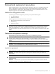
Removal and replacement procedures Review the specifications of a new component before installing it to make sure it is compatible with the server. When you integrate new components into the system, record its model and serial number, and any other pertinent information for future reference. After completing any removal or replacement procedure, run the diagnostics program to verify that all components operate properly.
This symbol indicates the presence of electric shock hazards. The area contains no user or field serviceable parts. Do not open for any reason. WARNING! To reduce the risk of injury from electric shock hazards, do not open this enclosure This symbol on an RJ-45 receptacle indicates a network interface connection. WARNING! To reduce the risk of electric shock, fire, or damage to the equipment, do not plug telephone or telecommunications connectors into this receptacle.
Server warnings and precautions WARNING! Hazardous voltages are present inside the server. Always disconnect AC power from the server and other associated assemblies while working inside the unit. Serious injury may result if this warning is not observed. WARNING! To reduce the risk of personal injury from hot surfaces, allow the hot-plug drives and the internal system components to cool before touching them.
Pre-installation procedure Perform the steps below before you open the server or before you remove or replace any component. WARNING! Failure to properly turn off the server before you open the server or before your start installing/ removing components may cause serious damage as well as bodily harm. 1. Turn off the server and all the peripherals connected to it. Refer to the “Powering down the server” section on the next page for detailed instructions on how to completely power down the server. 2.
Opening the server The top cover is detachable. You need to remove this cover before you can remove or replace a server component. To remove the top cover: 1. Perform steps 1 through 3 of the pre-installation procedure. 2. Detach the top cover from the chassis. a. Loosen the captive thumbscrew on the rear panel. b. Slide the cover approximately 1.25 cm (0.5 in) toward the rear of the unit, then lift the cover to detach it from the chassis. Figure 3 Removing the top cover 3.
Drive bay configuration The server supports three drive bays—two drive bays for 1-inch hard disk drives and one drive bay for a slim-type optical media drive. Go to the HP website at www.hp.com and refer to the options list for this server model for the latest information on supported hard drives and optical media drives.
Hard drive cable routing SCSI hard drive cable routing Figure 7 Cable routing for a SCSI hard drive Item Description 1 SCSI drive power cables 2 SCSI drive data cable when the controller card is installed in the standard height/full-length PCI-X riser board slot.
Optical media drive The optical media device bay supports the installation of a slim-type CD-ROM or DVD-ROM drive. To install a CD or DVD drive: 1. Perform the pre-installation procedure. 2. Prepare the optical media device bay for installation. a. Pull up the optical media device bay release lever, then push the drive carrier partially out through the front of the chassis. b. Pull the drive carrier out of the chassis. c. Remove the screw securing the drive carrier bezel. d.
5. Install the new optical drive into the chassis. a. Slide the optical drive assembly into the chassis until the media device bay release lever snaps into place. b. Route the optical drive’s power cables through the cable management opening of the chassis’ partition wall. c. Connect the IDE data and power cables to their corresponding connectors on the rear of the drive. Figure 11 Installing the optical drive assembly in the chassis 6. Perform the post-installation procedure.
Guidelines for installing hard drives • Install only hard drive models specified for your ProLiant server. Installing unsupported hard drives may damage the system by consuming power and generating heat in excess of the server’s operating tolerance. This condition may result in a loss of system and/or data integrity. • Install hard disks in the drive carriers included with the server chassis using four of the six HDD mounting screws pre-installed in each of the two HDD carriers.
Configuring a SCSI hard drive The steps listed below give an overview of the SCSI hard drive configuration procedure. 1. Install the SCSI hard drive. 2. Install the SCSI controller board. 3. Route the SCSI drive cables. 4. Set up the SCSI configuration. Refer to the documentation that came with the SCSI controller board for detailed procedures. To install a SCSI hard drive: 1. Perform the pre-installation procedure. 2. Select which drive bay you will use to install the new hard drive.
Figure 17 Removing the cover of the low-profile expansion slot Figure 18 Removing the cover of the standard height/full-length expansion slot 4. Remove the SCSI controller board from its protective packaging, handling it by the edges. Some controller boards can only be installed in one slot but other boards can be configured to fit in either slot by replacing the default bracket (attached to the board) with a different sized one.
Routing the SCSI drive cables Cable routing for SCSI hard drive varies depending on which expansion slot you installed the SCSI controller board—in the low-profile slot or in the standard height/full-length slot, and to a certain extent, to the location of the cable connectors on the SCSI controller board you installed.
c. Use the two retainer tabs on the air duct to secure the cable. d. Open the protective mylar sheet on the air duct. e. Lay the cable flat in the slot on the air duct surface. Figure 23 SCSI cable routing for low-profile controller boards phase 2 f. Fold the terminated end of the SCSI cable in the manner illustrated in the following figure. g. Reattach the mylar sheet over the cable back to the air duct surface. h.
3. Perform the post-installation procedure. 4. Set up the SCSI configuration. Refer to the documentation that came with the SCSI controller board for detailed procedures. To route the SCSI drive cables when the controller board is installed in the standard height/full-length expansion slot: 1. Connect the SCSI cable to the SCSI controller board. a. Connect the cable to the corresponding connector on the SCSI controller board. b.
d. Disconnect the following cables from their system board connectors—the 8-pin ATX processor power cable, the 24-pin ATX system board power cable, and the 4-pin I2C PSU cable. e. Route the SCSI cable underneath the three cables you disconnected in the previous step. f. Arrange the ATX processor power cable, the ATX system board power cable, and the I2C PSU cable over the routed SCSI cable, then reconnect them to their corresponding system board connectors.
Configuring a SATA hard drive Configuring a SATA hard drive is a two-step process that includes: 1. Install the SATA hard drive. 2. Set up the SATA configuration. For detailed procedures, refer to the Server Support CD or to the operating system documentation. To install a SATA hard drive: 1. Install the SATA hard drive following the procedures described in the “To install a SCSI hard drive:” section. 2. Route the SATA drive cables. a.
System board configuration Processor The server’s two mPGA604 sockets (U6 and U18) support dual-core Intel Xeon 800 MHz FSB processors with 1 and 2 MB on-die L2 cache. Figure 31 Intel mPGA604 processor sockets Guidelines for installing a processor • Processor socket 0 (U6) must always be populated. If no processor is installed in this socket, the system will fail to boot and halt during POST. This error prevents the system from functioning properly.
To remove a processor: CAUTION: To reduce the risk of personal injury from hot surfaces, allow the heat sink and the processor to cool before touching them. 1. Perform the pre-installation procedure. 2. If necessary, remove any accessory boards or cables that prevent access to the air duct. 3. Lift the air duct away from the processor sockets. Keep it for reinstallation later. Figure 33 Removing the air duct 4. Locate the processor you want to remove. 5. Remove the heat sink. a.
To install a processor: 1. Perform steps 1 through 3 of the previous section. 2. Locate an empty processor socket. 3. If you intend to install the new processor in processor socket 1—creating a dual-processor configuration— remove the processor air baffle first. a. Remove the screw securing the processor air baffle to the system board. b. Lift the processor air baffle away from the system board. Figure 36 Removing the processor air baffle CAUTION: Do not discard the processor air baffle.
A heat sink must be installed for the processor to function properly. The heat sink model for your ProLiant server already has a thermal interface material pre-applied on the bottom protected by a plastic cover. Make sure that this material has no scratches or gaps. If it does have any scratches or gaps, contact your HP Customer Support provider for replacement. CAUTION: To prevent overheating or a possible system crash, use only a heat sink model specified for the HP ProLiant DL140 Generation 2 server. 6.
Memory The system has eight DIMM slots that support up to 16 GB maximum system memory (2 GB in each of the eight DIMM slots). Figure 40 DIMM slots Guidelines for installing memory modules • Use only HP supported PC2-3200 (400 MHz) registered ECC DIMMs in 512 MB, 1 GB, or 2 GB capacities IMPORTANT: Use only HP supplied DIMMs. DIMMs from other sources can adversely affect data integrity.
To remove a memory module: 1. Perform the pre-installation procedure. 2. If necessary, remove any accessory boards or cables that prevent access to the DIMM slots. 3. Locate the memory module you want to remove. 4. Remove the selected memory module: a. Completely open the holding clips securing the module. This forces the module up in the slot and makes it easier to remove. b. Gently pull the memory module upward to remove it from its slot. Figure 41 Removing a memory module 5.
PCI expansion boards System board PCI expansion slots There are three PCI expansion slots on the system board.
PCI riser board assembly To remove the PCI riser board assembly: 1. Perform the pre-installation procedure. 2. Disconnect all cables connecting an existing expansion board to the system board. 3. Remove the PCI riser board assembly. a. Loosen the two captive thumbscrews that secure the assembly to the chassis. b. Lift the assembly away from the chassis.
3. Remove the PCI Express riser board from its protective packaging. 4. Install the PCI Express riser board on the assembly. a. Align the riser board on the full-length bracket side of the assembly. b. Secure the riser board to the assembly using the three screws you removed in step 2. c. Align the assembly with the system board expansion slots, then press it down to ensure full connection to the system board. d. Tighten the two captive thumbscrews to secure the assembly to the chassis.
Installing a PCI Expansion Board Guidelines for installing PCI expansion boards The system supports up to two expansion boards at a time. Use only HP supported expansion boards that meet the following specifications: • PCI or PCI-X compliant • Connector: 32 or 64 bits wide, 3.
To replace the system battery: 1. Remove the PCI riser board assembly. 2. If necessary, remove any accessory boards or cables that prevent access to the battery socket. 3. Replace the battery. IMPORTANT: Do not bend the spring latch during battery replacement. For proper operation, the latch must maintain a position of contact with the battery. a. Insert a small flat-blade screwdriver or a similar tool between the battery and spring latch to dislodge the battery from its socket. b.
System fan connections Figure 52 identifies the system fans by their device number and shows their corresponding cable connections. Figure 52 System fan connections Device number Connector System fan 1 to 4 CN1 to CN4 on the front panel board System fan 5 CN35 on the system board System fan 6 CN37 on the system board Note: System fans 1 to 5 are for the memory modules and processors, while system fan 6 is for the PCI slots and system chipsets.
4. Install a new system fan. a. Insert the new fan into the vacated fan bracket. b. Connect the fan cable to its corresponding board connector. If you are replacing system fan 1 – 4, connect the fan cable to the corresponding connector on the front panel board, then secure it through its fastener on the base of the chassis. If you are replacing system fan 5 or 6, route the fan cable through the opening in the center wall, then connect them to their corresponding connectors on the system board.
To replace the PSU: 1. Perform the pre-installation procedure. 2. Remove the default PSU. Keep the three screws you removed in this step for installing the new PSU later. a. Disconnect the processor power cable, the system board power cable, and the PSU I2C cable from the system board (CN15, CN21, and CN18 respectively), then disconnect the power cables of all installed drives from the PSU. b. Remove the PSU mounting screw located between the PSU fans. c.
Diagnostic tools Diagnostic tools overview The following utilities assist in diagnosing problems, testing hardware, and monitoring and managing server operations. Table 2 Diagnostic tools Tool What it is How to run it User Diagnostics A tool to assist testing and/or verifying operation of hardware. If problems are found, the diagnostics package isolates failures down to the replaceable part, whenever possible.
PhoenixBIOS Setup Utility NOTE: For ease of reading, PhoenixBIOS Setup Utility will be simply referred to as “Setup” or “Setup Utility” in this guide. Also, the screenshots used in this guide display default system values. These values may not be the same as those in your server. PhoenixBIOS Setup Utility is a hardware configuration program built into your system's Basic Input/Output System (BIOS).
Navigating through the Setup Utility Use the keys listed in the legend bar on the bottom of the Setup screen to work your way through the various menu and submenu screens of the Setup Utility. Table 3 Setup Utility’s navigation keys Key Function ← and → To move between selections on the menu bar. ↑ and ↓ To move the cursor to the field you want. The currently selected field will be highlighted. The right side of each menu screen displays a field help panel—Item Specific Help panel.
Table 4 Setup Utility's primary menus Menu Function Advanced Use this menu to: • Clear all configuration data in a section of memory for ESCD (Extended System Configuration Data), which stores the configuration settings for non-PnP plug-in devices. • Enable or disable support for the legacy USB bus. • Enable or disable RAID (Redundant Array of Inexpensive Disks) function for SATA devices. • Select which LAN port will be used for IPMI-related functions.
Boot-time diagnostic screen The boot-time diagnostic screen displays basic and important information about the current server configuration and is necessary for troubleshooting and may be required when asking for technical support.
System passwords The Security menu lets you set system passwords that would provide different levels of protection for the server. There are three types of passwords that you can set: • Supervisor password Entering this password will allow the user to access and change all settings in the Setup Utility. • User password Entering this password will restrict a user’s access to the Setup menus. A user can only access and modify the System Time, System Date, and Set User Password fields.
To remove a system password: 1. In the Security menu screen, select a set password field— Set User Password or Set Supervisor Password, then press Enter. 2. Type the original password then press Enter. 3. Press Enter twice without entering anything in the new and confirm password fields. 4. Press F10 to save the changes you made and close the Setup Utility. Setup automatically sets the selected password field to Clear.
Power-On Self Test (POST) When the server boots up, a series of tests are displayed on the screen. This is referred to as Power–On Self–Test or POST. POST is a series of diagnostic tests that checks firmware and assemblies to ensure that the server is properly functioning. This diagnostic function automatically runs each time the server is powered on.
Table 5 POST error messages Error code Error message Description/corrective action 0251 System CMOS checksum bad - Default configuration used The settings in the Setup Utility have been corrupted or modified incorrectly, perhaps by an application program that changes data stored in CMOS. You can either load the system default values or access Setup and enter your own custom values. If the error persists, check the system battery or contact your HP Customer Support provider.
POST beep codes The POST routines cannot display messages when an error occurs if any of the following are present: • The error occurs before the video display is initialized. • The video configuration fails, either there’s no graphics card installed or the one installed is faulty. • An external ROM module does not properly checksum to zero. • The system memory cannot be initialized. During these instances the server unit emits a buzzing sound followed by a series of audible beeps.
Table 6 POST beep codes Code Beep Description 22h 1-3-1-3 Test 8742 keyboard controller 24h Set ES segment register to 4 GB 28h Auto size DRAM 29h Initialize POST Memory Manager (PMM) 2Ah Clear 512 KB base RAM 2Ch 1-3-4-1 RAM failure on address line xxxx 2Eh 1-3-4-3 RAM failure on data bits xxxx of low byte of memory bus 2Fh Enable cache before system BIOS shadow 32h Test processor bus-clock frequency 33h Initialize Phoenix Dispatch Manager 36h Warm start shut down 38h Shadow sy
Table 6 POST beep codes Code Beep Description 67h Initialize multiprocessor APIC 68h Enable external and processor caches 69h Setup System Management Mode (SMM) area 6Ah Display external L2 cache size 6Bh Load custom defaults (optional) 6Ch Display shadow-area message 6Eh Display possible high address for UMB recovery 70h Display error messages 72h Check for configuration errors 76h Check for keyboard errors 7Ch Set up hardware interrupt vectors 7Dh Initialize Intelligent System Mo
Table 6 POST beep codes Code Beep Description A0h Set time of day A2h Check key lock A4h Initialize typematic rate A8h Erase F2 prompt AAh Scan for F2 key stroke ACh Enter Setup AEh Clear boot flag B0h Check for errors B1h Inform ROM pilot about the end of POST.
Table 6 POST beep codes Code Beep Description E3h Initialize system timer E4h Initialize system I/O E5h Check force recovery boot E6h Checksum BIOS ROM E7h Go to BIOS E8h Set huge segment E9h Initialize multiprocessor EAh Initialize OEM special code EBh Initialize PIC and DMA ECh Initialize memory type EDh Initialize memory size EEh Shadow boot block EFh System memory test F0h Initialize interrupt vectors F1h Initialize runtime clock F2h Initialize video F3h Initialize Sy
POST-related troubleshooting Perform the following procedures when POST fails to run or display error messages or emit beep codes. If the POST failure is during a routine bootup, check the following: • All external cables and power cables should be firmly plugged in. • The power outlet to which the server is connected is working. • The server and monitor are both turned on. The bicolor power status LED indicator on the front panel must be lit up green.
Connectors, switches, and LEDs Connectors and components Front panel components Figure 62 Front panel Item Icon Component 1 Hard disk drive (HDD) bays 2 Optical media device bay 3 Unit identification (UID) button with LED indicator (blue) Press to illuminate the UID LED indicators on the front and rear panels. This is to mark a particular unit within a server group for purpose of identification during servicing or maintenance procedures.
Rear panel components Figure 63 Rear panel Item Icon Component 1 Ventilation holes 2 Thumbscrew for the top cover 3 Thumbscrews for the PCI riser board assembly 4 Low profile 64-bit/133 MHz PCI-X riser board slot cover 5 Standard height/full-length 64-bit/133 MHz PCI-X riser board slot cover 6 Power supply cable socket 7 GbE LAN ports for NIC 1 and NIC 2 (RJ-45) 8 UID button with LED indicator (blue) This button mirrors the function of the UID button located on the front panel. 9 USB 2.
System board components Figure 64 System board components Item Component code Component 1 LAN1 10/100 Mbps LAN port for IPMI management 2 JK2 PS/2 mouse port 3 JK1 PS/2 keyboard port 4 CN11 Serial port 5 CN9 Video port 6 CN5 and CN8 USB 2.
Item Component code Component 21 CN40 9-pin connector for the front USB 2.
System switches System configuration switch Figure 65 System configuration switch Table 7 System configuration switch settings Switch Status Function SW1-1 On Off Boot block enabled Normal boot SW1-2 On Off Clear CMOS settings and restore system defaults Normal CMOS settings SW1-3 — Reserved SW1-4 — Reserved Note: The status indicated in bold text is the default setting.
Front panel board components The front panel board is linked to the system board through the front panel board connector (CN12).
Front panel board cable routing Figure 68 Front panel board cable routing Item Connector Cable 1 JP1 Front panel board power cable Connects to the PSU. 2 CN9 Front panel board system board cable Connects to CN12 on the system board. 3 CN1 to CN4 4-pin system fan cables Connects to the system fans 1 to 4. To route the front panel board cables: CAUTION: Route the front panel board cables neatly. If necessary, secure them using the pre-installed cable clips located on the chassis base.
Status LED indicators This different status LED indicators aid in problem diagnosis by indicating the status of system components and operations of the server. Front panel LED indicators Figure 69 Front panel LED indicators Item LED indicator Status Description 1 UID LED indicator (recessed underneath the UID button) Blue A UID button has been pressed. 2 System health LED indicator Off System health is normal. Amber A pre-failure system threshold has been breached.
Rear panel LED indicators Figure 70 Rear panel LED indicators Item LED indicator Status Description 1 NIC activity/link status LED indicators Solid green An active network link exists. Flashing green An ongoing network data activity exists. Off The server is off-line. 2 NIC network speed LED indicators Steady amber The LAN connection is using a GbE link. Steady green The LAN connection is using a 100 Mbps link. Off The LAN connection is using a 10 Mbps link.
System specifications Technical specifications System unit Table 8 System unit specifications Item Description Processor socket Dual Intel mPGA604 socket Processor support Intel Xeon 800 MHz FSB processor Core logic chipsets • • • Super I/O chipset SMSC LPC47M192 Hardware monitoring chipset Analog Devices ADM1026 Baseboard management controller QLogic Zircon UL Gigabit Ethernet controller Broadcom BCM5721 NetXtreme (two) Onboard 10/100 Mbps LAN controller SMSC LAN91C113I-NC LAN Memory cont
Memory Table 9 Memory specifications Item Description Size 512 MB, 1 GB, and 2 GB Speed 400 MHz (PC2-3200) Type DDR2-400 registered ECC DIMMs Processor Table 10 Processor specifications Item Description Operating frequency 2.8, 3.4, and 3.6 GHz On-die L2 cache 1 and 2 MB Process technology 90 nm Package Flip Chip Micro Pin Grid Array IDE CD-ROM drive Table 11 IDE CD-ROM drive specifications Item Description Dimensions Height Width Depth 12.7 mm (0.5 in) 128 mm (5.04 in) 137.2 mm (5.
Table 11 IDE CD-ROM drive specifications Item Description Laser parameters Type Wave length Output power Semiconductor laser 795 nm <0.25 mW Operating conditions Temperature Humidity 5° to 55°C (41° to 131°F) 10% to 90% RH Hard drives SCSI hard drive Table 12 SCSI hard drive specifications Item 36 GB 72 GB Model HP SCSI Ultra320 Hard Drive Capacity 36419.2 MB Interface Ultra320 SCSI Physical dimensions Height Width 25.4 mm (1.0 in) 101.6 mm (4.
SATA hard drive Table 13 SATA hard drive specifications Item 80 GB 160 GB Model HP Serial-ATA (SATA) Hard Drive Capacity 80,000 MB Interface Serial ATA Physical dimensions Height Width 26.11 mm (1.028 in) 101.6 mm (4.0 in) Seek time (typical reads, including settling) Single track Average Full-stroke 0.9 ms 9.0 ms 17.0 ms Rotational speed 7,200 rpm Maximum transfer rate (synchronous) 1.
Controllers Storage controller Table 15 Storage controller specifications Item Description Model Integrated in the Intel 82801ER ICH5R Connector 7-pin SATA connector Protocol SATA and Ultra ATA/100 compatible • 2 channel Ultra ATA/100 (only one channel is used by the system) • 2 channel SATA Maximum data transfer rate (SATA) 1.5 GB/s Features • • Alert Standard Format (ASF) System Management controller for network manageability PCI Rev 2.3 and ACPI 2.
Environmental specifications Table 18 System environmental specifications Item Description Temperature Operating Non-operating (unpacked) Storage (unpacked) Shipping (packed) 10° to 35°C (50° to 95°F) 0° to 50°C (32° to 122°F) 5° to 40°C (41° to 104°F) -40° to 70°C (-40° to 158°F) Relative humidity (non-condensing) Operating Non-operating 10% to 90% RH 5% to 95% RH Note: Operating temperature has an altitude derating of 1°C per 300 M to 3000 M.
Index A D AC power: connector, 57; disconnecting, warning, 12; power-down procedures, 13 air duct: installing, 30; part number, 6; removing, 28 diagnostics: accessing, 41; HP ROMPaq Utility, 41; IPMI Event Log, 41; overview, 41; PhoenixBIOS software, 41; User Diagnostics, 41 DIMM slots: configuring, 44; location, 31 dip switch.
I I/O ports.
power-down procedures, 13 power-on password, 46 Power-On Self-Test. See POST Preboot Execution Environment.