HP ProLiant DL140 Generation 3 Server Software Configuration User Guide Part number: 416132-001 First edition: October 2006
Legal notices © Copyright 2006 Hewlett-Packard Development Company, L.P. The information contained herein is subject to change without notice. The only warranties for HP products and services are set forth in the express warranty statements accompanying such products and services. Nothing herein should be construed as constituting an additional warranty. HP shall not be liable for technical or editorial errors or omissions contained herein.
Contents System BIOS configuration System BIOS overview .............................................................................................................................. 4 PhoenixBIOS software .............................................................................................................................. 4 PhoenixBIOS Setup Utility .........................................................................................................................
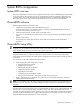
System BIOS configuration System BIOS overview Basic Input/Output System or BIOS is a set of programs permanently stored in an EEPROM chipset (U64) located on the system board. These programs serve as an interface between the server’s hardware components and its operating system. Your ProLiant server features the PhoenixBIOS software—a ROM BIOS-based diagnostic tool that monitors system activity and performs constant hardware testing to ensure proper system operation.
Accessing the Setup Utility 1. Turn on the monitor and the server. If the server is already turned on, save your data and exit all open applications, then restart the server. 2. During POST, press F10. If you fail to press F10 before POST is completed, you will need to restart the server. The first page to be displayed will be the Main menu showing the Setup Utility’s menu bar. Use the left (←) and right (→) arrow keys to move between selections on the menu bar.
Table 1 Setup Utility’s navigation keys Key Function F1 or Alt-H To bring up the General Help window. The General Help window describes other Setup navigation keys that are not displayed on the legend bar. F9 Press to load default system values. F10 Press to save changes and close the Setup Utility. Setup Utility primary menus The Setup Utility’s menu bar displays the six primary menu selections. For detailed information and related screenshots of these Setup menus, refer to the succeeding sections.
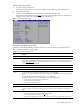
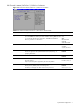
IDE Channel 0 Master/SATA Port 1/SATA Port 2 submenu Figure 3 IDE Channel 0 Master/SATA Port 1/SATA Port 2 submenu Table 3 IDE Channel 0 Master/SATA Port 1/SATA Port 2 submenu fields Field Description Options Type Select the type of drive connected to the related port. None If you select None, the related port will be disabled. Selecting User will allow User you to manually edit the device information, while Auto will enable the Auto device to provide its own information.
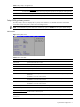
Boot Features submenu Figure 4 Boot Feature submenu Table 4 Boot Features submenu fields Field Description Options Summary Screen Choose whether to display the boot-time diagnostic screen during POST. For more information on what this screen display, go to page 20. Enabled Disabled QuickBoot Mode Enabling this mode allows the system to skip certain POST items during bootup. This will decrease the time needed to boot the system. Enabled Disabled NumLock Select the NumLock behavior during bootup.
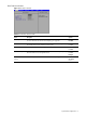
Advanced menu Figure 5 Setup Advanced menu Table 5 Advanced menu fields Field Description Options Reset Configuration Data Select whether to erase data in the section of memory for ESCD (Extended System Configuration Data) which stores the configuration settings for non-PnP plug-in devices. Yes No NIC Option Select which LAN port to use for console redirection. Dedicated NIC Side-band NIC 8042 Emulation Support Select whether to enable emulation support for the 8042 keyboard controller.
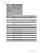
Advanced Chipset Control submenu Figure 6 Advanced Chipset Control submenu Table 6 Advanced Chipset Control submenu fields Field Description Options SERR Signal Condition Select the ECC error condition that will prompt a SERR#. None Single Bit Multiple Bit Both 4 GB PCI Hole Granularity Select the granularity of PCI hole for PCI resource. 128 MB 256 MB 1.0 GB 2.0 GB Memory Branch Mode Select the type of memory branch mode to employ.
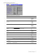
USB Control submenu The USB Control submenu allows users to select which functions to enable for available USB devices. Figure 7 USB Control submenu Advanced Processor Options submenu Figure 8 Advanced Processor Options submenu Table 7 Advanced Processor Options submenu fields Field Description Options Hyperthreading Select whether to enable the Intel Hyper-Threading (HT) Technology function. HT enables the host operating system to view a single physical processor to appear as two logical processors.
Table 7 Advanced Processor Options submenu fields Field Description Options Discrete MTRR Allocation If enabled, Memory Type Range Registers (MTRRs) are configured as distinct, separate units with no overlapping. This will allow users to achieve better graphic effects when using a Linux graphic driver that requires a writecombining configuration with 4GB or more memory.
PCI Slots Configuration submenu Figure 11 PCI Slots Configuration submenu Table 9 PCI Slots Configuration submenu fields Field Description Options Option ROM Scan When enabled, this setting will initialize the device expansion ROM for the related PCI slot. Enabled Disabled Enable Master When enabled, the selected device is set as the PCI bus master. Enabled Disabled Latency Timer Set the clock rate for the PCI bus master. Note: Different operating systems require different bus master clock rate.
Console Redirection submenu Figure 13 Console Redirection submenu Table 11 Console Redirection submenu fields Field Description Options Console Redirection Select whether to enable console redirection. Console redirection (C.R.) enables users to manage the system from a remote location using an in-band connection. The most common in-band remote-management hardware device is a network adapter.
IPMI submenu Figure 14 IPMI submenu Table 12 IPMI submenu fields Field Description IPMI Specification Version System’s IPMI standard compliance BMC Firmware Version of the system BMC firmware LAN Settings Displays the current LAN configuration settings. Press Enter to access the related submenu. System Event Log Displays the configuration settings related to the system event log. Press Enter to access the related submenu.
Table 13 LAN Settings submenu fields Field Description Options BMC Telnet Service Select whether to enable the BMC Telnet service. Enabled Disabled BMC Ping Response Select whether to enable the ICMP ping response function. Enabled Disabled BMC HTTP Service Select whether to enable the BMC HTTP service.
Realtime Sensor Data submenu The Realtime Sensor Data submenu displays the current values for various hardware monitors, including their minimum and maximum threshold levels. Status for the system switches and the ACPI function are also displayed. Use the PgUp and PgDn keys to view the whole record. Figure 18 Realtime Sensor Data submenu Security menu The Security menu allows users to set an administrator password.
To change the administrator password: 1. In the Security menu screen, select the Administrator Password Is field, then press Enter. 2. Type the original password in the password box. 3. Type a new password, then press Enter. 4. Retype the new password to verify the first entry, then press Enter again. 5. Press F10 to save the password and close the Setup Utility. To remove the administrator password: 1. In the Security menu screen, select the Administrator Password Is field, then press Enter. 2.
Power menu Figure 22 Setup Power menu Table 16 Power menu fields Field Description Options Resume on Modem Ring Select whether to wake up system when an incoming call is detected on the modem (via the serial port). Off On Wake on LAN Select whether to wake up system when a LAN activity is detected (via the onboard LAN controller or an add-on LAN card). Enabled Disabled After Power Failure Specify the power state to resume to after a system shutdown that is due to an interruption in AC power.
Boot-time diagnostic screen The boot-time diagnostic screen displays basic and important information about the current server configuration and is necessary for troubleshooting and may be required when asking for technical support.
CMOS backup utility There are third-party utilities that read the CMOS settings and record them to a regular file, which can then be backed up through normal means, or copied to an external storage media. Some of these utilities also offer the option of restoring the CMOS settings so you need not re-enter them manually. These utilities are not always compatible with all versions of CMOS or types of CMOS. The same applies to the operating system version.
Power-On Self Test (POST) When the server boots up, a series of tests are displayed on the screen. This is referred to as Power–On Self–Test or POST. POST is a series of diagnostic tests that checks firmware and assemblies to ensure that the server is properly functioning. This diagnostic function automatically runs each time the server is powered on.
Table 18 POST error messages Error code Error message Description/corrective action 0251 System CMOS checksum bad - Default configuration used The settings in the Setup Utility have been corrupted or modified incorrectly, perhaps by an application program that changes data stored in CMOS. You can either load the system default values or access Setup and enter your own custom values. If the error persists, check the system battery or contact your HP Customer Support provider.
Table 19 lists the checkpoint codes written at the start of each test and the beep codes issued for terminal errors.
Table 19 POST beep codes Code Beep 45h 46h Description POST device initialization 2-1-2-3 Check ROM copyright notice 47h Initialize I20 support 48h Check video configuration against CMOS 49h Initialize PCI bus and devices 4Ah Initialize all video adapters in system 4Bh Quiet boot start (optional) 4Ch Shadow video BIOS ROM 4Eh Display BIOS copyright notice 4Fh Initialize multi-boot 50h Display processor type and speed 51h Initialize EISA board 52h Test keyboard 54h Set key click
Table 19 POST beep codes Code Beep Description 84h Detect and install external parallel ports 85h Initialize PC-compatible PnP ISA devices 86h Re-initialize onboard I/O ports.
Table 19 POST beep codes Code Beep Description BCh Clear parity checkers BDh Display Multi-boot menu BEh Clear screen (optional) BFh Check virus and backup reminders C0h Try to boot with INT 19 C1h Initialize POST Error Manager (PEM) C2h Initialize error logging C3h Initialize error display function C4h Initialize system error handler C5h PnP and dual CMOS (optional) C6h Initialize note dock (optional) C7h Initialize note dock late C8h Force check (optional) C9h Extended checks
Table 19 POST beep codes Code Beep Description F4h Output one beep F5h Clear huge segment F6h Boot to mini DOS F7h Boot to full DOS System BIOS configuration 28
RAID configuration RAID overview RAID–redundant array of independent (originally, inexpensive) disks–is a method of replicating the same data on multiple hard disks (thus, redundantly). In this system’s case, in two SATA hard drives. By storing data on multiple locations, I/O operations can be performed in parallel boosting system performance. RAID also improves system reliability by increasing the mean time between failures (MTBF).
9. In the Option menu box, select Array Configuration Utility. 10. In the Main Menu box, select Configure Drives. 11. Select the hard drives you want to include in the RAID setup, then press Enter. A warning message appears. 12. Type Yes then press Enter. The selected drives will be configured with array information. 13. After the completing the initial drive configuration, select Create Arrays in the Main Menu. 14. Select the hard drives you want to include in the array, then press Enter. 15.
Network operating system (NOS) installation Supported NOS Table 20 List of supported NOS NOS Version On-line information site Microsoft Windows Microsoft Windows 2003 Server—Enterprise, Standard, and Web Editions Microsoft Windows Server 2003 R2—Enterprise, Standard, and Web Editions Microsoft Windows Vista—Enterprise, Standard, and Web Editions Microsoft World Wide Web access: www.microsoft.com Microsoft Product Support Services: http://support.microsoft.
Installing Microsoft Windows NOS The procedures in this section apply to all Microsoft Windows NOS versions supported by your ProLiant server. Refer to Table 20 for a list of these NOS versions. Pre-installation instructions 1. Complete the pre-NOS installation procedures listed on page 31. 2. Have the following installation requirements on hand: • HP ProLiant DL140 Generation 3 Server Support CD • The applicable Microsoft Windows NOS CD-ROM(s) • Six blank, formatted 3.
2. Follow the procedures corresponding to the type of hard disk that is installed in the server. 3. In the Welcome to Setup screen, press Enter to continue. 4. Press F8 to accept the licensing agreement. 5. In the drives partitioning screen, select the target drive. If you want to use the entire drive to install the Windows NOS then press Enter. Otherwise, press C to create a drive a partition. NOTE: Windows Server 2003 does not have the 2-GB limitation present in Windows NT 4.0.
Phase 2 - Installing the HP LAN driver During the Windows NOS installation, the OS may not detect the embedded HP network interface card. The following procedure will help you install the LAN driver using the Support CD. 1. Insert the Support CD in the server’s optical media drive. By default, the Support CD will automatically run displaying the Welcome page. Close this window. However, if this does not occur, double-click the Startup.htm file located on the root directory of the Support CD. 2.
3. Verify if the installed drivers are digitally signed. a. In the Device Manager window, select the device (e.g. HP AHA-29160) that you want to verify. b. Right-click Properties | Driver. c. Locate the Digital Signer. If the driver of that device is digitally signed then it will display "Microsoft Windows Publisher" or "Microsoft Windows Hardware Compatibility Publisher”. If the driver of the device is not digitally signed we recommend that you check HP’s website at www.hp.
11. Click Start | Settings | Control Panel | Administrative Tools. 12. Check that the following services are now available: • Terminal Services Client Creator • Terminal Services Configuration • Terminal Services Manager To create the client installation diskettes: 1. Double-click Terminal Services Client Creator. 2. Select the appropriate client type for your environment. 3. Click Format disk if needed. 4.
To test the network link using Terminal Services: 1. Click Start | Programs | Terminal Services Client | Terminal Services Client on a client you installed Terminal Services on. 2. Select the target server from the Available Servers list displayed on the screen. 3. Click Connect. 4. Complete the User ID and Password login form. Phase 3 - Configuring the domain controller setup The Windows NOS manual calls this process "Promoting the server to a domain controller”. 1.
Section 6. Installing additional HP accessories The HP ProLiant DL140 Generation 3 Server Support CD includes the drivers for accessories compatible with your server. Refer to the product manual enclosed with the accessory for the detailed installation procedure and/or to the attached readme.txt file associated with the driver. The readme.txt file can be found on the appropriate driver diskette.
Installing Red Hat Enterprise Linux NOS Installation flow 1. Install Red Hat Enterprise Linux 3 [version]. For particular procedure for each RHEL NOS version, refer to succeeding sections. 2. Install additional HP accessories. The HP ProLiant DL140 Generation 3 Server Support CD includes the drivers for accessories compatible with your server. Refer to the product manual enclosed with the accessory for the detailed installation procedure and/or to the attached readme.txt file associated with the driver.
Disk Partitioning Setup HP recommends selecting the automatic partitioning mode. 1. Click Autopartition to continue. 2. Remove all system partitions, then select a hard drive. 3. Click Next to continue. 4. If a Warning dialog box appears, click Yes to continue. 5. In the Partitioning dialog box, click OK. Boot Loader Configuration HP recommends selecting the Use GRUB Boot Loader option. 1. Select Use GRUB Boot Loader, then click OK. 2.
Section 3. Installing Red Hat Enterprise Linux 3 Installation to Begin Once you complete the customization, the installation program asks for confirmation before proceeding with the install. Click OK to proceed. You may be prompted to insert the rest of the RHEL3 CD-ROMs, depending on the packages you have chosen to install. Video Card Configuration The video controller for your ProLiant server is integrated in the Server Engines Pilot chipset.
Section 2. Customizing the installation Language Selection Select the language of choice you prefer for the installation, then click Next to continue. Keyboard Configuration Your HP server comes with a generic 104-key PC keyboard. After selecting the appropriate option for the keyboard layout type, click Next to continue. Disk Partitioning Setup HP recommends selecting the automatic partitioning mode. 1. Click Automatically partition to continue. 2.
Section 3. Installing Red Hat Enterprise Linux 4 About to Install Once you complete the customization, the installation program asks for confirmation before proceeding with the install. 1. Click Next to proceed with the installation. 2. In the Required install media dialog box, click Continue to start installation. You may be prompted to insert the rest of the RHEL4 CD-ROMs, depending on the packages you have chosen to install.
Installing SUSE Linux Enterprise Server NOS The procedures in this section apply to the SUSE Linux Enterprise Server NOS, version 9 and 10. Installation flow 1. Install SUSE Linux Enterprise [version]. For particular procedure for each SLE NOS version, refer to succeeding sections. 2. Install additional HP accessories. The HP ProLiant DL140 Generation 3 Server Support CD includes the drivers for accessories compatible with your server.
Section 3. Completing the installation Root Password Enter a root password consisting of at least six alphanumeric characters, then click Next to continue. Network Configuration Review the Network Configuration settings and see to it that they fit your environment, then click Next to continue. Test Internet Connect Skip this test. You can test the network connection after completing the NOS installation. Click Next to proceed with the installation.
Section 1. Installing SUSE Linux Enterprise Server 10 1. Turn on the server and insert the SUSE Linux Enterprise Server 10 (SLES10) CD 1. 2. Reboot the system to the SLES10 CD 1. 3. Select Installation, then press Enter to proceed to the customization of your installation. Section 2. Customizing the Installation Language Select the language of choice you prefer for the installation, then click Accept to continue. Media Check Skip this stage of the installation. Click Next to continue.
Add a New Local User Follow the prompt to add a new local user account, then click Next to continue. Release Note Review the release notes, then click Next to continue. Hardware Configuration Review the default hardware settings and modify them if necessary, then click Next to continue. Installation Completed Click Finish to reboot the system and proceed to the login window.
Installing Sun Solaris 10 Perform the procedures in this section to install Sun Solaris 10 to your ProLiant server Pre-installation instructions 1. 2. Complete the pre-NOS installation procedures listed on page 31. Have the following installation requirements on hand: • HP ProLiant DL140 Generation 3 Server Support CD • Sun Solaris 10 Update 1 DVD NOTE: You must first install a DVD-compatible optical media drive in your ProLiant server before installing Sun Solaris 10.
Section 2. Customizing the installation The Sun Solaris10 Installer shifts to a text-based screen for customizing the hardware selection and other options. Use the arrow keys to navigate through them and press F2 to enable a setting. Kdmconfig – View and Edit Window System Configuration 1. Click Change Pointing Device, then press F2. 2. Select the pointing device used by your system, then press F2. 3. Select Change Video Device/Monitor, then press F2. 4.
Section 3. Completing the installation Welcome The Welcome screen appears. Click Next to proceed with the installation. Installation Options Retain the default installation option settings, then click Next to continue. Specify Media Click CD/DVD, then click Next to initialize the installation process. License Read the license agreement. If the terms of the agreement are acceptable, select the Accept check box, then click Next to continue.
Server management Server management overview Server management on the HP ProLiant DL140 G3 provides the user with the status of various system sensors, and the ability to manage and control some of the system functionalities remotely. The features and details of these functionalities are covered in the Lights-Out 100 User Guide. The information in this chapter is geared towards helping the user configure and use some of the basic server management features of the HP ProLiant DL140 G3.
Remote management interfaces The following paragraphs provide examples on how to use the various interfaces. The CLI and KCS interfaces provide the user with advanced management features as specified in the Lights-Out 100 User Guide. Web interface This is a basic interface that allows the user access to the server information. From a web browser, the user needs to type in the IP address of the server. To access the remote management web interface: 1.
6. From the remote system open a DOS window and type in telnet . 7. Enter the login name and password. The Lights-Out 100 Management screen will be displayed. Figure 26 CLI interface screen via a NIC port To use the COM port for CLI interface access: 1. Connect a peer-to-peer modem cable between the system’s COM port and a Windows client PC. A client PC running a different OS can also be used as long as it supports HyperTerminal capability. 2.
7. Start connection by clicking the phone icon on the HyperTerminal toolbar. 8. Press Esc once, then press Shift + 9. This will switch the COM port mode from System to CLI. 9. Log in to system BMC by entering the user name (admin) and password (admin). To illustrate, to change to map1 directory, type cd map1 to change directory to map1. /./-> cd map1 /./map1/-> KCS command line interface This interface allows the user to access the ProLiant server by booting it into DOS.
Index A IPMI, 15 Item Specific Help panel, 5 administrator password: changing, 18; definition, 17; removing, 18; resetting, 18; setting, 17 K B L Basic Input/Output System.