HP ProLiant DL140 Server Maintenance and Service Guide November 2003 (First Edition) Part Number 349117-001 2003 Hewlett-Packard Development Company, L.P. Microsoft® and Windows NT® are U.S. registered trademarks of Microsoft Corporation. Intel® and Pentium® are U.S. registered trademarks of Intel Corporation. Hewlett-Packard Company shall not be liable for technical or editorial errors or omissions contained herein.
Contents About This Guide ..................................................................................................................iv Audience Assumptions....................................................................................................iv Technician Notes.............................................................................................................iv Where to Go for Additional Help......................................................................................
Power Supply ................................................................................................................ 25 Battery........................................................................................................................... 27 Memory Modules........................................................................................................... 29 Processor ..................................................................................................................
About This Guide This maintenance and service guide can be used for reference when servicing an HP ProLiant DL140 server. WARNING: To reduce the risk of personal injury from electric shock and hazardous energy levels, only authorized service technicians should attempt to repair this equipment. Improper repairs can create conditions that are hazardous. Audience Assumptions This guide is for service technicians.
CAUTION: To properly ventilate the system, you must provide at least 7.6 cm (3.0 in) of clearance at the front and back of the server. CAUTION: The computer is designed to be electrically grounded (earthed). To ensure proper operation, plug the AC power cord into a properly grounded AC outlet only. NOTE: Any indications of component replacement or printed wiring board modifications may void any warranty.
1 Illustrated Parts Catalog This chapter provides the illustrated parts breakdown and spare parts list for the HP ProLiant DL140 server. The table in this chapter provides names and ordering numbers for all referenced spare parts.
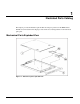
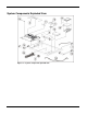
System Components Exploded View Figure 1-2: System components exploded view HP ProLiant DL140 Server Maintenance and Service Guide 2
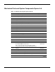
Mechanical Parts and System Components Spares List Table 1-1: Mechanical and System Spare Parts List Item Description Spare Part Number Mechanical Components 1 Access panel (top cover) 348801-001 2 Front Bezel, Mylar and screws 348797-001 3 Single Fan 348795-001 4 Hardware and Plastics Kits 348798-001 4a) HDD Bracket (Drive not included) 4b) CD Bracket (CD-ROM Drive not included) 4c) Processor Heatsink Retention Module* 4d) Cable Tie Downs* 4e) Fan Bracket 4f) System Board Screws* Power 5 32
Table 1-1: Item Mechanical and System Spare Parts List continued Description Spare Part Number Hardware 13 ATA hard drive, 80 GB 294934-004 14 Replacement battery, 3-V lithium 166899-001 15 Hard drive cable 348799-001 16 Optical CD-ROM cable 348799-001 17 Optical CD-ROM assembly backplane 348799-001 18 Front USB cable 348800-001 19 Return kit* 349586-001 20 Country kit* 349411-001 20a) Startup, Documentation and Utilities CD 20b) Important Safety Information Guide 20c) Limited War
2 Removal and Replacement Procedures This chapter provides subassembly and module-level removal and replacement procedures for HP ProLiant DL140 servers. After completing all necessary removal and replacement procedures, run the diagnostics program to verify that all components operate properly.
Symbols on Equipment Any surface or area of the equipment marked with these symbols indicates the presence of a hot surface or hot component. WARNING: To reduce the risk of injury from a hot component, allow the surface to cool before touching it. To reduce the risk of injury from electric shock hazards, do not open this enclosure. WARNING: Any surface or area of the equipment marked with these symbols indicates the presence of electric shock hazards.
Server Warnings and Precautions WARNING: To reduce the risk of personal injury from hot surfaces, allow the hot-plug drives and the internal system components to cool before touching them. WARNING: To reduce the risk of electric shock or damage to the equipment: • Do not disable the power cord grounding plug. The grounding plug is an important safety feature. • Plug the power cord into a grounded (earthed) electrical outlet that is easily accessible at all times.
Powering Down the Server The server does not completely power down when the front panel power button is pressed. The button toggles server power between On and Standby. In Standby, the server removes power from most electronics and drives, portions of the power supply and some internal circuitry remain active. To completely remove all power from the system, disconnect the power cord from the server.
Top Cover To access the system board, processor, memory modules, expansion slot, and other internal components, remove the top cover. Observe the following warnings and cautions. WARNING: The front panel Power On/Off switch does not completely shut off all system power. Portions of the power supply and some internal circuitry remain active until AC power is removed. WARNING: To reduce the risk of personal injury from hot surfaces, allow the internal system components to cool before touching them.
To remove the top cover: 1. Power down the server. See “Powering Down the Server” in this chapter. 2. Loosen rear thumbscrew. 3. Slide the top cover approximately 1.25 cm (0.5 in) toward the rear of the unit and lift the panel to remove it (1). Figure 2-1: Removing the top cover To replace the top cover, reverse steps 1 through 3.
Optical CD-ROM Drive Assembly To remove the Optical CD-ROM drive assembly: 1. Power down the server. See “Powering Down the Server” in this chapter. 2. Remove the top cover. See “Top Cover” in this chapter. 3. Remove the CD-ROM cable and power cable (1). 4. Press in and hold the CD-ROM latch (2) 5. Slide the tray toward the rear of the server until the USB connectors are visible (3). 6. Lift the CD-ROM tray out of the server (4).
Hard Drive Overview The server contains two drive bays for ATA hard drives. There are two ATA channels. One channel is dedicated to the hard drives and the other to the CDROM. The server ships standard with two 1-inch drive trays for use with two 1-inch ATA hard drives. The following sections provide general guidelines and installation procedures for installing or upgrading hard drives.
Hard Drive Identification Numbers The servers include two 1-inch hard drive trays. Hard drives installed in the server are labeled as Device 0 and Device 1 in the following illustration for clarification. IMPORTANT: Always populate hard drive bays starting with the lowest ATA device number.
Hard Drives To remove a hard drive from the hard drive bay: 1. Power down the server. See “Powering Down the Server” in this chapter. 2. Remove the top cover. See “Top Cover” in this chapter. 3. Disconnect the ATA cables from hard drives (1,2). Figure 2-4: Disconnecting the cables from the ATA hard drives 4. Disconnect the power cables from the hard drives.
5. Remove the hard drive and hard drive tray: a. Remove the screw that secures the hard drive tray to the chassis (1). b. Slide the tray toward the rear of the server and lift the tray out of the chassis (2). Figure 2-6: Removing the hard drive tray from the chassis 6. Remove the four screws that secure the hard drive to the hard drive tray (1). 7. Remove the hard drive from the hard drive tray (2).
Power Switch Board To remove the Power Switch Board: 1. Power down the server. See “Powering Down the Server” in this chapter. 2. Remove the top cover. See “Top Cover” in this chapter. 3. Remove the cable attached to the Power Switch Board. 4. Remove the two screws (1) and slide the Power Switch Board toward the rear of the server (2) and lift to remove the board. IMPORTANT: Remove the Power Switch Board carefully to avoid damaging the LEDs.
PCI Riser Board Assembly To remove the PCI riser board assembly: 1. Power down the server. See “Powering Down the Server” in this chapter. 2. Remove the top cover. See “Top Cover” in this chapter. 3. Disconnect any cables connecting an existing expansion board to the system board. 4. Lift and remove the assembly from the server chassis (1).
Expansion Board To remove an expansion board: CAUTION: To avoid the risk of damage to the system or expansion boards, remove all power cords before installing or removing an expansion board. When the front panel power switch is off, auxiliary power is still connected to the PCI expansion slot and may damage the card. 1. Power down the server. See “Powering Down the Server” in this chapter. 2. Remove the top cover. See “Top Cover” in this chapter. 3. Disconnect all cables from the expansion board. 4.
Fan Bracket To remove the fan bracket: 1. Power down the server. See “Powering Down the Server” in this chapter. 2. Remove the top cover. See “Top Cover” in this chapter. 3. Remove the PCI riser board assembly. See “PCI Riser Board Assembly” in this chapter. WARNING: To reduce the risk of personal injury from hot surfaces, allow the internal system components to cool before touching them. 4. Disconnect the fan bracket fan cables (1~5) from the fan connectors on the system board.
5. Loosen the fan bracket thumbscrew (1). 6. Push the fan bracket toward the power supply side of the chassis to clear the alignment tab and lift fan bracket out (2). Figure 2-12: Unlocking the fan bracket and clearing the fan bracket alignment tab Reverse steps 1 through 6 to replace the fan bracket. IMPORTANT: See Server Access Panel Label or System Board Connecter section later in this manual for correct fan cable connections.
Fans The server contains five system fans. The fans are located on the fan bracket. Use the following figure and table to locate the system fans. Figure 2-13: Locating the system fans NOTE: Fans are spared and replaced individually. spare.
Cables The following sections of this guide contain removal and replacement procedures for the standard cables that ship with the server: • ATA/100 cables • Optical CD-Rom Drive Assembly cable. • Front USB cables. ATA Hard Drive Cables To remove the ATA cables: 1. Power down the server. See “Powering Down the Server” in this chapter. 2. Remove the top cover. See “Top Cover” in this chapter. 3. Remove the PCI riser board assembly. See “PCI Riser Board Assembly” in this chapter. 4.
Optical CD-ROM Drive Assembly Cable To remove the optical CD-ROM drive assembly cable: 1. Power down the server. See “Powering Down the Server” in this chapter. 2. Remove the top cover. See “Top Cover” in this chapter. 3. Remove the PCI riser board assembly. See “PCI Riser Board Assembly” in this chapter. 4. Remove the fan bracket. See “Fan Bracket” in this chapter. 5. Disconnect the optical CD-ROM drive assembly cable from the optical device assembly backplane (1). 6.
Front USB Cable To remove the Front USB cable: 1. Power down the server. See “Powering Down the Server” in this chapter. 2. Remove the top cover. See “Top Cover” in this chapter. 3. Remove the PCI riser board assembly. See “PCI Riser Board Assembly” in this chapter. 4. Remove the fan bracket. See “Fan Bracket” in this chapter. 5. Remove the optical CD-ROM drive assembly; see “Optical CD-ROM Drive Assembly” in this chapter. 6. Remove the hard drive tray(s), See “Hard Drive” in this chapter. 7.
Power Supply To remove the power supply: 1. Power down the server. See “Powering Down the Server” in this chapter. 2. Remove the top cover. See “Top Cover” in this chapter. 3. Remove the PCI riser board assembly. See “PCI Riser Board Assembly” in this chapter. 4. Remove the fan bracket. See “Fan Bracket” in this chapter. 5. Disconnect the hard drive power cables from the hard drives (1). 6. Disconnect the optical CD-ROM drive assembly power cable from the optical CD-ROM drive assembly (2). 7.
Figure 2-17: Removing the power supply Reverse steps 1 through 9 to replace the power supply.
Battery If the server no longer automatically displays the correct date and time, check the battery that provides power to the real-time clock. If necessary, replace a used battery with a CR2032 lithium battery. Under normal use, battery life is at least 5 years. WARNING: This server contains either an internal lithium manganese dioxide, or a vanadium pent oxide battery. There is a risk of fire and burns if the battery pack is not handled properly.
To remove the battery: 1. Power down the server. See “Powering Down the Server” in this chapter. 2. Remove the top cover. See “Top Cover” in this chapter. 3. Locate the battery on the system board (1). Figure 2-18: Locating and removing the system battery 4. If necessary, remove the PCI riser board assembly to access the battery location. See “PCI Riser Board Assembly” in this chapter. 5. Press the battery release lever away from the battery (2). 6.
Memory Modules The server supports up to four PC2100 DDR ECC registered SDRAM DIMMs installed in four sockets on the system board. NOTE: Populate the DIMM sockets in descending sequential order, starting with DIMM socket 4.
Observe the following guidelines when installing additional memory: • DIMMs must be industry-standard, 512-MB, or 1-GB, 3-cm (1.2-in), 184-pin PC2100, 266-MHz DDR ECC memory DIMMs. The DDR memory DIMMs must support CAS Latency 2, where CL=2 or greater. They must also contain the mandatory Joint Electronic Device Engineering Council (JEDEC) Serial Presence Detect (SPD) information. • DIMMs installed in the server must be registered DDR, 2.5 volts and 64-bits wide.
6. To install a DIMM, gently push the DIMM into the socket on the system board (1). As the DIMM enters the socket and is properly seated, the latches close (2). Figure 2-21: Installing a DIMM in a DIMM socket CAUTION: Use only HP supplied DIMMs. DIMMs from other sources can adversely affect data integrity. 7. Press down firmly on the DIMM while pushing the latches inward until the latches snap into place.
Processor CAUTION: Always use a new heatsink when replacing processors. Failure to use new components can cause damage to the processor. To remove the processor: 1. Power down the server. See “Powering Down the Server” in this chapter. 2. Remove the top cover. See “Top Cover” in this chapter. 3. Locate the processor on the system board.
4. Disengage the retaining clips on each side of the heatsink (1). 5. Remove the heatsink from the top of the processor (2). Figure 2-23: Disengaging the heatsink retaining clips (one on each side) and removing the heatsink (both retaining clips disengaged) 6. Lift the processor locking lever (1) and lift the processor from the socket (2). Figure 2-24: Removing the processor from the system board Reverse steps 1 through 6 to reinstall the processor and heatsink.
System Board To remove the system board: 1. Power down the server. See “Powering Down the Server” in this chapter. 2. Remove the top cover. See “Top Cover” in this chapter. 3. Remove the PCI riser board assembly. See “PCI Riser Board Assembly” in this chapter. 4. Disconnect the fan cables 1 through 5. See “Fans” in this chapter. 5. Remove any DIMMs. See “Memory Modules” in this chapter. 6. Remove the fan bracket. See “Fan Bracket” in this chapter. 7. Disconnect the power supply from the system board.
3 Diagnostic Tools This chapter provides an overview of the software and firmware diagnostic tools available for HP ProLiant DL140 servers. Diagnostic Tools Utility Overview The following utilities assist in diagnosing problems, testing hardware, and monitoring and managing server operations. Table 3-1: Diagnostic Tools Tool What it is How to run it User Diagnostics A tool to assist testing and/or verifying operation of hardware.
4 Connectors, Switches, and LED Indicators This chapter contains illustrations and tables identifying and describing connectors, switches, and LED indicator locations on the front panel, rear panel, system board, and hard drives for the HP ProLiant DL140 server. Connectors This section contains figures and tables showing connector locations on the front panel, rear panel, PCI riser board assembly, and the system board of the server.
Table 4-1: Rear Panel Connectors Item Description 1 Power connector 2 Mouse connector 3 Dual USB connector 4 RJ-45 GbE connector for NIC 2 (supports WOL, PXE) 5 Expansion slot 6 RJ-45 GbE connector for NIC 1 (supports WOL, PXE) 7 Video connector 8 Serial connector 9 Keyboard connector Expansion Slot Connector The following figure and table shows the PCI expansion board slot connector and expansion board slot cover.
System Board Connectors The following figure and table show system board connectors on the system board.
System Switches The server has a switch bank (SW1) for system configuration Refer to the labels on the inside of the server top cover or to the following sections for the proper switch settings. The following figure and table show the location of the system switch.
System Configuration Switch (SW1) The system configuration switch (SW1) is a four-position switch used for system configuration. Refer to the labels attached to the inside of the server top cover for proper system configuration settings. The following table shows the shipping system configuration switch settings of SW1.
Figure 4-5: Front panel LEDs Table 4-6: Front Panel LEDs Item LED Description Status 1 Optical CD-ROM drive activity 2 Power On/Off Button 3 NIC 2 link/activity 4 NIC 1 link/activity 5 Server Status 6 Hard drive activity On = Activity Off = No activity Green = System has AC power and is turned on. Off = Standby mode or System is not powered on. Blinking Green = Hibernate.
Rear Panel LED Indicators The server rear panel contains two LEDs that allow monitoring of network activity and server identification.
Internal LED Indicator The system board contains an internal power status LED for use during troubleshooting operations. When the LED is illuminated, adequate power is available to the system from the power supply. If the LED is not illuminated, either the power cord is not connected or the power supply has failed.
IPMI Event Log Code List The IPMI Event Log Code List can be used in conjunction with the IPMI Event log found in the BIOS setup to assist in troubleshooting of the unit. Fan Discrete Event/Reading class. Sensor numbers are from 01h to 05h. Error Type* * See IPMI event log description details. Memory Discrete Event /Reading class. Sensor number is 06h. Error Type Data1 Data2 Data3 Correctable ECC 00h FFh FFh Uncorrectable ECC 01h FFh FFh Processor Discrete Event /Reading class.
Temperature Discrete Event /Reading class. Sensor number is 0Ch. Error Type Thermal Trip State asserted Data1 Data2 Data3 01h FFh FFh Threshold Event /Reading class. Sensor numbers are 0Ah, 0Bh and 0Dh.
Error Type Data1 Data2 Data3 DMAC_PAGE_REG_ERR E0h 04h 02h DMAC1_CH_REG_ERR E0h 04h 03h DMAC2_CH_REG_ERR E0h 04h 04h TIMER_COUNT_RW_ERR E0h 04h 05h KBC_BAT_TEST_ERR E0h 07h 01h INSERT_FUNC_KEY_ERR E0h 07h 02h KBD_LOCK_ERR E0h 07h 03h KBC_INTERFACE_ERR E0h 07h 04h NO_KBD_ERR E0h 07h 05h DISPLAY_MEMORY_ERR E0h 0Ah 01h CMOS_DISPLAY_ERR E0h 0Ah 02h Option ROM initialization C0h 08h FFh Video initialization C0h 09h FFh Keyboard controller initialization C0
5 Specifications This chapter provides operating and performance specifications for HP ProLiant DL140 server components and optional hardware, including: • System unit • Power supply • Memory • Optical CD-ROM drive Assembly • Integrated Ultra ATA/100 controller • Optional ATA hard drives • Integrated Dual Broadcom 10/100/1000 NICs (Wake on LAN and PXE capable) HP ProLiant DL140 Server Maintenance and Service Guide 47
System Unit Table 5-1: System Unit Specifications Item Description Height 4.37 cm (1.72 in) Depth 60.22 cm (23.7 in) Width 43.0 cm (16.9 in) Weight (maximum) 11.00 kg (24.2 lb) U.S. and international input voltage requirements Rated input voltage 100 VAC to 240 VAC Rated input frequency 50 Hz to 60 Hz Rated input current 4.5A (100-120 V) / 2.
Power Supply Table 5-2: Power Supply Specifications Item Description Input characteristics Rated input voltage 100 VAC to 240 VAC Rated input line 110VAC / 220 VAC Frequency range 50 to 60 Hz Rated input power 440 W Rated input current 4.5 A (100 V) to 2.1 A (240 V) Output characteristics Steady state power 325 W Maximum peak power 422 W for 15 seconds.
Optical CD-ROM Drive Table 5-4: Optical CD-ROM Drive Specifications Item Description Applicable disk formats CD-DA, CD-ROM (mode 1 and 2); CD-XA (mode 2, Form 1 and 2), CD-1 Ready; CD-Extra; Video CD, Photo CD (single and multiple session) Capacity 550 MB (mode 1, 12 cm) 640 MB (mode 2, 12 cm) Block size 2638, 2352 bytes (mode 0); 2352, 2340, 2336, 2048 bytes (mode 1); 2352, 2340, 2336, 2048, bytes (mode 2) Dimensions (Bezel Included) Height 1.27 cm (0.5 in) Depth 13.17 cm (5.39 in) Width 13.
Integrated Ultra ATA/100 Controller Table 5-5: Ultra ATA/100 Controller Specifications Item Description Simultaneous drive transfer channels 2 channels Transfer rate synchronous (Max) 100 MBps Data transfer method 32-bit PCI bus master Drive support Ultra ATA, EIDE & Fast ATA-2 PCI bus transfer rate (maximum) 266 MBps Data transfer modes UDMA Modes 5/4/3/2/1/0, DMA Modes 2/1/0, PIO Modes 4/3/2/1/0 Protocol ATA/100 compatible Feature CRC (Cyclical Redundancy Check) Buffer size 128 byte Op
Integrated Broadcom 10/100/1000 Gigabit Server Auto-Switching Network Interface Controller (NIC) Table 5-7: Integrated Broadcom 10/100/1000 Gigabit Server Auto-Switching Network Interface Controller (NIC) Specifications (WOL and PXE capable) Item Description Network interface 10Base-T/100Base-TX/1000Base-T Ethernet Compatibility IEEE 802.3 Data transfer method 64-bit, 133MHz PCI(X)1.