
HP ProLiant DL145 Generation 2 Server Installation Sheet


HP ProLiant DL145
Generation 2 Server
Installation Sheet
Read instructions completely before beginning
installation procedure
© Copyright 2005 Hewlett-Packard Development Company, L.P.
The information contained herein is subject to change without notice. The only
warranties for HP products and services are set forth in the express warranty
statements accompanying such products and services. Nothing herein should be
construed as constituting an additional warranty. HP shall not be liable for technical
or editorial errors or omissions contained herein.
HP ProLiant DL145 Generation 2 Server Installation Sheet
First Edition (March 2005)
Part Number 381743-001
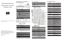
Identifying Server Components
Front Panel Components
Table 1: Front Panel Components
Item Icon Component
1 Hard disk drive (HDD) bays
2 Optical media device bay
3
Unit identification (UID) button with LED
indicator (blue)
4
System health LED indicator (amber)
5
Activity/link status LED indicators for NIC 1 and
NIC 2 (green)
6
HDD activity LED indicator (green)
7
Power button with LED indicator
(bicolor: green and amber)
8 Thumbscrews for the front bezel
9
USB 2.0 ports
Rear Panel Components
Table 2: Rear Panel Components
Item Icon Component
1 Ventilation holes
2 Thumbscrew for the top cover
3 Thumbscrews for the PCI riser board assembly
4 Low profile 64-bit/133 MHz PCI-X riser board slot
cover
5 Standard height/full-length 64-bit/133 MHz PCI-X
riser board slot cover
Users can convert the PCI-X functionality of this slot
to PCI Express using the PCI Express riser board
option kit.
6 Power supply cable socket
7
GbE LAN ports for NIC 1 and NIC 2 (RJ-45)
8
UID button with LED indicator (blue)
9
USB 2.0 ports (black)
10
Video port (blue)
11
Serial port (teal)
12
PS/2 keyboard port (purple)
continued
Table 2: Rear Panel Components continued
Item Icon Component
13
PS/2 mouse port (green)
14 10/100 Mbps LAN port for IPMI management
(RJ-45)
NOTE: The three LAN ports each has its own LED indicators for
activity/link status and network speed.
System Board Components
Table 3: System Board Components
Item Component
Code
Component
1
RJ1 10/100 Mbps LAN port for IPMI
management
2 JK2 PS/2 mouse port
3 JK1 PS/2 keyboard port
4 CN13 Serial port
5 CN9 Video port
6
USB1 and
USB2
USB 2.0 ports
7 SW3 UID button with LED indicator (blue)
8 LAN1 and
LAN2
GbE LAN ports for NIC 1 and NIC 2
9 U20 and U27 Pulse H5007 XFORM 10/100 Base-T
transformer modules
10 U23 and U30 Broadcom BCM5721 NetXtreme Gigabit
Ethernet controllers A and B
continued
Table 3: System Board Components continued
Item Component
Code
Component
11 CN7 and CN8 64-bit/133 MHz 3.3 V PCI-X slots
12 DIMM1 to
DIMM4
Processor 1 socket (U22) DIMM slots
13 U22 AMD Opteron 940-pin processor 1 socket
14 U11 AMD Opteron 940-pin processor 2 socket
15 — Airflow regulator for system fans
1 through 4
16 DIMM5 to
DIMM8
Processor 2 socket (U11) DIMM slots
17
U42 PCI Express x16 slot
18 U46 Analog Devices ADM1026 hardware
monitor chipset
19 CN12 8-pin ATX processor power connector
20 FAN5 and FAN6 4-pin system fan connectors
21
SATA1 and
SATA2
7-pin 150-MBps SATA connectors
22 CN21 4-pin I
2
C connector for PSU
23 CN28 9-pin connector for the front USB 2.0
ports
24 CN22 24-pin ATX system board power
connector
25 JP5 System reset
26 — PCI retainer bracket
27 CN26 9-pin front panel board connector
28
CN29 4-pin SCSI cable LED connector
29 U54 NVIDIA Crush K8-04 Professional MCP
(Media and Communications Processor)
30 CN27 IDE data cable connector
31 U74 BIOS flash EEPROM (Electrically Erasable
Programmable Read-Only Memory)
32 BUZ1 Internal speaker
33 U55 AMD-8132 HyperTransport PCI-X 2.0
tunnel
34 CN25 LPC debug connector
35 BT1 3 V internal lithium system battery
36 SW2 System configuration switch (dip switch)
37 U79 SMSC LPC47M192 Super I/O chipset
38 U60 16 MB DDR SDRAM
39 SW1 NMI (non-maskable interrupt) switch
40 U56 NVIDIA GeForce2 MX400 GPU (Graphics
Processor Unit)
41 U82 SMSC LAN91C113I-NC LAN controller
(10/100 Mbps)
42
U52 BMC flash EPROM
43 CN23 BMC debug port
44 U67 QLogic Zircon UL BMC (Baseboard
Management Controller)
45 U47 IC61LV25616-10T BMC SRAM