HP ProLiant DL145 Generation 3 Server Software Configuration Guide Part number: 430494-002 Second edition: March 2007
Legal notices © Copyright 2006, 2007 Hewlett-Packard Development Company, L.P. The information contained herein is subject to change without notice. The only warranties for HP products and services are set forth in the express warranty statements accompanying such products and services. Nothing herein should be construed as constituting an additional warranty. HP shall not be liable for technical or editorial errors or omissions contained herein.
Contents System BIOS configuration System BIOS overview .............................................................................................................................. 5 PhoenixBIOS software .............................................................................................................................. 5 PhoenixBIOS Setup Utility .........................................................................................................................
Contents 4
System BIOS configuration This chapter describes the basic functions of the PhoenixBIOS software. System BIOS overview A Basic Input/Output System, or BIOS, is a set of programs permanently stored in an EEPROM chipset (U70) located on the system board. These programs serve as an interface between the server’s hardware components and its operating system.
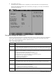
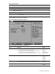
2. During POST, press F10. If you fail to press F10 before POST is completed, you need to restart the server and repeat this step. The first page displayed is the Main menu. Use the left (←) and right (→) arrow keys to move between selections on the menu bar. Figure 1 Main menu Navigating through the Setup Utility Use the keys listed in the legend bar on the bottom of the Setup screen to access the various menu and submenu screens of the Setup Utility.
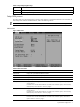
Table 1 Setup Utility navigation keys Key Function F9 Loads the default system values. F10 Saves all changes to settings and closes the Setup Utility. Setup Utility menus The Setup Utility menu bar displays the five primary menu selections. For detailed information and screenshots of these Setup menus and their related submenus, refer to the following sections. NOTE: In the table following each menu screenshot, options in boldface are the system default settings.
Table 2 Main menu fields Field Description System Memory Displays the amount of conventional memory detected during POST. Extended Memory Displays the amount of extended memory detected during POST. NOTE: If you install additional memory, the system automatically adjusts the System Memory and Extended Memory fields to reflect the new memory size. Set System Asset Text Enter the server asset tag. System Serial Number Enter the server serial number.
Table 3 Primary Master/Primary Slave submenus fields Field Description Options Transfer Mode Selects the method for transferring the data between the related device and the system memory. Setup only lists the options supported by the drive and platform. Standard Fast PIO 1 Fast PIO 2 Fast PIO 3 Fast PIO 4 FPIO 3/DMA 1 FPIO 4/DMA 2 Ultra DMA Mode Enables the related device to employ an Ultra Direct Memory Access (UDMA) Disabled mode in transferring data.
Table 4 Boot Options submenu fields Field Description Options Error Message Handling Enables a length of time for the system to stop booting and wait for user input Disabled after detecting an error. If this option is disabled, the system continues to Wait 5 seconds boot. Wait 30 seconds Wait Forever Halt On Error Enables the system to stop POST and wait for user input when a POST error is detected.
Table 5 Advanced menu fields Field Description Options I/O Device Configuration Displays the settings related to the serial port. Press Enter to access the related submenu. For details on the submenu options, see the “I/O Device Configuration submenu” section on page 15. Console Redirection Displays the settings related to console redirection. Press Enter to access the related submenu. For details on the submenu options, see the “Console Redirection submenu” section on page 16.
PCI Configuration submenu The PCI Configuration submenu displays options to view settings related to the expansion slots and the onboard Ethernet controller. Figure 7 PCI Configuration submenu Table 7 PCI Configuration submenu fields Field Description Options Option ROM Expansion Selects whether to increase or relocate memory during ROM expansion time if errors occur when option ROMs are initialized.
PCI Device, Slot #1/2 submenu Figure 8 PCI Device, Slot #1/2 submenu Table 8 PCI Device, Slot #1/2 submenu fields Field Description Options Option ROM Scan Selects whether the device expansion ROM for the related PCI slot is initialized. Enabled Disabled Enable Master Selects whether the device is set as the PCI bus master. Disabled Enabled Latency Timer Sets the clock rate for the PCI bus master.
Embedded Broadcom BCM5715 submenu Figure 9 Embedded Broadcom BCM5715 submenu Table 9 Embedded Broadcom BCM5715 submenu fields Field Description Options Option ROM Scan Selects whether to initialize device expansion ROM, making the device bootable. Enabled Disabled Serial ATA submenu In the Serial ATA window, you can select which functions to enable for available SATA devices.
Field Description Options Embedded SATA Enables the embedded SATA controller. Disabled Enabled SATA mode PATA Selects native SATA mode or parallel ATA (PATA) emulation mode. Use the native SATA mode if you are installing a Linux operating system. Use SATA the PATA setting if you are installing Microsoft Windows. CAUTION: If you do not change the SATA mode setting to PATA before you install Windows with the default ATA driver, the operating system will hang.
Table 11 I/O Device Configuration submenu fields Field Description Options Base I/O Address Indicates the serial port base address. 3F8 2F8 3E8 2E8 Interrupt Indicates the serial port IRQ setting. IRQ 4 IRQ 3 Serial port Mode Selects the IPMI serial port operation mode. When set to System, the system System controls the serial port. When set to BMC, the baseboard management Shared controller (BMC) controls the serial port.
Table 12 Console Redirection submenu fields Field Description Options Console connection Selects whether the console is connected directly to the system or through a modem. Direct Via modem Continue C. R. after POST Enables console redirection after POST. Off On # of video pages to support Selects the number of video pages to allocate for console redirection when video hardware is not available.
Table 13 IPMI submenu fields Field Description Options BIOS POST Watchdog When enabled, the system automatically reboots once the watchdog timer count (set by the host operating system) reaches zero. A watchdog timer triggers a system reboot if the main program detects a faulty condition, with the goal of resuming normal operation.
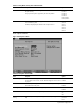
System Event Log submenu Figure 15 System Event Log submenu Table 15 System Event Log submenu fields Field Description Options Log POST errors Selects whether IPMI records all POST errors in the system event log. Disabled Enabled Clear System Event Log Selects whether to delete all system event log (SEL) entries during the next system startup. Existing Event Log number Displays the number of recorded SEL entries. Remaining Event Log number Displays the number of remaining SEL entries.
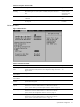
Figure 16 System Event Log example Realtime Sensor Data example The Realtime Sensor Data window displays the current values for various system temperature and voltage monitors. The minimum and maximum threshold levels are also indicated. You can use the Page Up and Page Down keys to browse through the data. Figure 17 Realtime Sensor Data example Security menu The Security menu allows users to set an administrator password.
Figure 18 Security menu To set an administrator password: 1. In the Security menu screen, in the Set Supervisor Password field, press Enter. The Set Supervisor Password window displays. Figure 19 Setting a supervisor password 2. Type a new password in the Enter New Password box, then press Enter. The password may consist of up to eight alphanumeric characters (A-Z, a-z, 0-9). 3. Type the same password in the Confirm New Password box to verify the first entry, then press Enter. 4.
Figure 21 Changing a supervisor password 2. Type the original password in the Enter Current Password box, then press Enter. 3. Type a new password in the Enter New Password box, then press Enter. 4. Type the new password again in the Confirm New Password box, then press Enter. 5. Press Enter to continue after the Setup Notice window displays that the changes have been saved. 6. Press F10 to save the password and close the Setup Utility. To remove the administrator password: 1.
Figure 22 Boot menu Exit menu The Exit menu displays several options on how to quit the Setup Utility. Select any of the exit options then press Enter. Figure 23 Exit menu Table 16 Exit menu options Option Description Exit Saving Changes Save the changes made and close the Setup Utility. Keyboard shortcut: F10 Exit Discarding Changes Discard changes made and close the Setup Utility.
Table 16 Exit menu options Option Description Load Setup Defaults Loads the default settings for all BIOS setup fields. Keyboard shortcut: F9 Discard Changes Discards all changes made in the Setup Utility. Save Changes Saves changes made in the Setup Utility. Boot-time diagnostic screen The boot-time diagnostic screen displays basic and important information about the current server configuration and is necessary for troubleshooting and may be required when asking for technical support.
Loading system defaults If the system fails after you make changes in the Setup menus, reboot the server, enter Setup, and load the system default settings to correct the error. These default settings have been selected to optimize the server’s performance. Setup default settings are quite demanding in terms of resource consumption. If you are using lowspeed memory chips or other types of low-performance components and you choose to load these settings, the system might not function properly.
Error message 1 of 1: Error code 0103 Keyboard not detected - Keyboard error In some cases an error message may include recommendations for troubleshooting or require that you press the Enter key to display recommendations. Follow the instructions on the screen. Table 17 lists the most common POST error messages with their corresponding troubleshooting recommendation. It is recommended that you correct the error before proceeding, even if the server appears to boot successfully.
POST beep codes There are several POST routines that issue a POST terminal error and shut down the system if they fail. Before shutting down the system, the terminal-error handler issues a beep code signifying the test point error, writes the error to port 80h, attempts to initialize the video, and writes the error in the upper left corner of the screen (using both mono and color adapters). NOTE: An optional POST code expansion board must be installed in the server for the POST beep codes to be audible.
Table 18 POST Beep Codes Code Beep 14h 16h Description Initialize keyboard controller 1-2-2-3 BIOS ROM checksum 17h Initialize cache before memory auto size 18h 8254 timer initialization 1Ah 8237 DMA controller initialization 1Ch Reset programmable interrupt controller 20h 1-3-1-1 Test DRAM refresh 22h 1-3-1-3 Test 8742 keyboard controller 24h Set ES segment register to 4 GB 26h Enable gate A20 line 28h Autosize DRAM 29h Initialize POST memory manager 2Ah Clear 512 KB base RAM
Table 18 POST Beep Codes Code Beep Description 51h Initialize EISA board 52h Test keyboard 54h Set key click if enabled 55h Enable USB devices 56h Enable keyboard 57h Enable FireWire devices 58h 2-2-3-1 Test for unexpected interrupts 59h Initialize POST display service 5Ah Display prompt ”Press F10 to enter SETUP” 5Bh Disable processor cache 5Ch Test RAM between 512 and 640 KB 5Eh Test base memory 60h Test extended memory 62h Test extended memory address lines 64h Jump to us
Table 18 POST Beep Codes Code Beep Description 8Bh Test and initialize PS/2 mouse 8Ch Initialize floppy controller 8Eh Autotype hard drive size 8Fh Determine number of ATA drives (optional) 90h Initialize hard disk controllers 91h Initialize local bus hard disk controllers 92h Jump to user patch 2 93h Build MP table for multiprocessor boards 95h Install CD-ROM for boot 96h Clear huge ES segment register 97h Fix up MP table 98h 1-2 Search for option ROMs.
Table 18 POST Beep Codes Code Beep Description C0h Try to boot with INT 19 C1h Initialize POST Error Manager (PEM) C2h Initialize error logging C3h Initialize error display function C4h Initialize system error handler C5h PnP and dual CMOS (optional) C6h Initialize note dock (optional) C7h Initialize note dock late C8h Force check (optional) C9h Extended checksum (optional) CAh Redirect Int 15h to enable remote keyboard CBh Redirect Int 13h to memory technologies devices such as RO
Reprogramming the BIOS with the crisis recovery jumper If the BIOS becomes corrupted, use the crisis recovery jumper to reprogram the BIOS. You will also need a USB floppy drive and the HP crisis recovery floppy disk. The crisis recovery jumper is on jumper block P56 on the system board. Refer to the HP ProLiant DL145 Generation 3 Server Maintenance and Service Guide for the location of this jumper block and the crisis recovery setting. To reprogram the BIOS: 1.
NOS installation Supported NOS Table 19 Supported network operating systems (NOS) NOS Version On-line information site Microsoft Windows Microsoft Windows Server 2003—Enterprise, Standard, and Web Editions Microsoft Windows Server 2003 R2—Enterprise, Standard, and Web Editions Microsoft Windows Server 2003 for 64-bit Extended Systems—Enterprise and Standard Editions Microsoft Windows Server 2003 R2 for 64-bit Extended Systems—Enterprise and Standard Editions Microsoft Windows Vista (32- and 64-bit)— Ent
Installing Microsoft Windows NOS The procedures in this section apply to all Microsoft Windows NOS versions supported by your ProLiant server. Refer to Table 19 on page 33 for a list of these NOS versions. CAUTION: If you install the default ATA driver from the installation CD, you must change the SATA mode setting in the Serial ATA submenu from SATA to PATA; otherwise, the operating system kernel will hang. See the “Serial ATA submenu” section on page 14 for more information.
Press F6 if you want to install a third party controller; otherwise, proceed to step 2. NOTE: If you missed pressing F6 before the message is invalidated, you need to reboot the system to display the message prompt again. 2. Follow the procedures corresponding to the type of hard disk that is installed in the server. 3. At the Welcome to Setup screen, press Enter to continue. 4. Press F8 to accept the licensing agreement. 5. At the drives partitioning screen, select the target drive.
Phase 2 - Installing the HP network driver During the Windows NOS installation, the OS may not detect the embedded HP network interface card. The following procedure helps you install the LAN driver using the Support CD. 1. Insert the Support CD in the server’s optical media drive. By default, the Support CD automatically runs and displays the Welcome page. Close this window. 2. Click Start | Settings | Control Panel | System | Hardware | Device Manager. 3.
NOTE: The Windows NOS Event Viewer may have recorded network errors because your network is not yet configured. Please disregard these errors. 6. Close the Event Viewer window. Phase 2 - Initializing the hard drive There are two types of hard drive configurations: Dynamic and Basic. You can select the appropriate type by right-clicking on the disk drive icon. • Dynamic drives are used to create volumes, which can contain more than one physical hard drive.
Section 5. Configuring the network Phase 1 - Configuring the server’s IP address During the installation process, the system was configured to use DHCP. If no DHCP server is found on the network, the system autoconfigures a random IP address to start functioning. It is important that you configure the proper IP address to be able to communicate with the clients. 1. Right-click My Network Places | Properties, then double-click Local Area Connection on your server.
5. Click Next at Domain Controller Type to accept the default setting—Domain controller for a new domain. 6. Click Next at Create Tree or Child Domain to accept the default setting—Create a new domain tree. 7. Click Next at Create or Join Forest to accept the default setting—Create a new forest of domain trees. 8. At the Full DNS name for new domain text box, type in the assigned DNS name for your server (for example: mycompany.com). 9. Click Next.
Pre-installation instructions 1. Complete the NOS pre-installation procedures listed on page 33. 2.
4. Review the Boot Manager setting and modify it if necessary, then click OK. 5. Select to install the boot loader in MBR, then click OK. Network Configuration for eth0 Review the IP setting for eth0 and verify that it fits your environment, then click OK to continue. Network Configuration for eth1 Review the IP setting for eth1 and verify that it fits your environment, then click OK to continue. Hostname Configuration Enter a system hostname, then click OK to continue.
Red Hat Enterprise Linux 4 installation The procedures in this section apply to all versions of the Red Hat Enterprise Linux 4 supported by your ProLiant server. Refer to Table 19 on page 33 for a list of these NOS versions. NOTE: If the system has more than 4 GB of memory, the Red Hat Enterprise Linux installation requires the pci=nommconf parameter. Section 1. Launching the Red Hat Enterprise Linux 4 installer 1. Turn on the server and insert the Red Hat Enterprise Linux 4 CD 1.
Package Group Selection Review and modify the selection as necessary, then click Next to continue. If you selected the Custom install option, pre-determined packages have already been selected. However, depending upon your network environment additional packages may be necessary. NOTE: Remember to select the appropriate package groups that match your network settings. For example, the DNS Name Server package may be required if you have set-up your new server to be the DNS controller. Section 3.
2. Install additional HP accessories. The HP ProLiant DL145 Generation 3 Server Support CD includes the drivers for accessories compatible to your server. Refer to the product manual enclosed with the accessory for the detailed installation procedure and/or to the attached readme.txt file associated with the driver. The readme.txt file can be found on the appropriate driver diskette. Pre-installation instructions 1. 2. Complete the NOS pre-installation procedures listed on page 33.
Test Internet Connect Skip this test. You can test the network connection after completing the NOS installation. Click Next to proceed with the installation. Service Configuration Review the Services settings and select those items that are required by your environment, then click Next to continue. User Authentication Method Select the authentication method appropriate for your environment, then click Next to continue.
Password for the System Administrator Enter a root password consisting of at least six alphanumeric characters, then click Next to continue. Network Configuration Review the Network Configuration settings and verify that they fit your environment, then click Next to continue. Test Internet Connect Review the Network Configuration settings and verify that they fit your environment, then click Next to continue. Installation Setting Review the installation settings once again, then click Next to continue.
Sun Solaris 10 installation Section 1. Launching the Sun Solaris10 installer 1. Turn on the server and insert the Sun Solaris 10 DVD. 2. Reboot the system to the SS10U1 DVD. 3. Click Solaris, then press Enter. 4. Type 1 to select the Solaris Interactive Installation option. After a few minutes, the Proposed Window System Configuration for Installation list appears. These settings are incorrect and should be modified. 5. Press Esc to modify the settings and customize the installation. Section 2.
Root Password Enter a root password. Re-enter the password in the second box, then click Next to continue. Confirm Information A configuration information summary is displayed. Verify this information, then click Confirm to proceed to the installation proper. Section 3. Completing the installation Welcome The Welcome screen appears. Click Next to proceed with the installation. Installation Options Retain the default installation option settings, then click Next to continue.
Do you need to override the system’s default NFS version 4 domain name? Keep the default setting (No), then press Enter to proceed to the login window.
Server management Pre- and post-installation procedures Pre-installation procedures WARNING! Failure to properly turn off the server before you open the server or before you start removing or installing hardware components may cause serious damage as well as bodily harm. WARNING! To reduce the risk of personal injury from hot surfaces, allow the chassis and any installed hardware components to cool before touching them.
b. Tighten the captive screw on the rear panel. 5. Connect all external cables and the AC power cord to the system. Route the cables properly through the available cable management arrangement. 6. Press the power button on the front panel to turn on the server. Configuring the BMC The server includes a BMC for systems management, which you can access through a 10/100 Mbps LAN port for IPMI management. To access the BMC through this LAN port, you must configure the IP address.
To enable console redirection via the Setup Utility: 1. In the I/O Device Configuration submenu, set the Serial port Mode field to BMC. See the “I/O Device Configuration submenu” section on page 15 for more information. 2. In the Console Redirection submenu, set the Com Port Address to On Board Com Port A. See the “Console Redirection submenu fields” section on page 16 for more information. 3. Press F10 to Save and Exit.
Index 3 32 Bit I/O setting, 8 32-Bit Memory Hole setting, 11 A administrator password, 20; changing, 21; definition, 20; removing, 22; resetting, 22; setting, 21 After Power Failure setting, 10 B Base I/O Address setting, 16 baseboard management controller. See BMC Basic Input/Output System.
submenu, 14; Exit menu, 23; General Help window, 6; I/O Device Configuration submenu, 15; IPMI submenu, 17; Item Specific Help panel, 6; LAN Settings submenu, 18; legend bar, 6; loading system defaults, 25; Main menu, 7; Memory Controller Options submenu, 11, 12; menu bar, 7; menus, 7; navigation keys, 6; non-user-configurable field, 6; overview, 5; PCI Device, Slot # submenu, 13; POST, 25; Primary Master submenu, 8; Primary Slave submenu, 8; Realtime Sensor Data submenu, 20; recording Setup values, 24; Sec