HP ProLiant DL145 Generation 3 Server Maintenance and Service Guide Part number: 430047-004 Fourth Edition: April 2007
Legal notices © Copyright 2006, 2007 Hewlett-Packard Development Company, L.P. The information contained herein is subject to change without notice. The only warranties for HP products and services are set forth in the express warranty statements accompanying such products and services. Nothing herein should be construed as constituting an additional warranty. HP shall not be liable for technical or editorial errors or omissions contained herein.
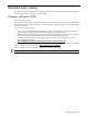
Contents Illustrated parts catalog Customer self-repair (CSR)......................................................................................................................... 4 Mechanical parts exploded view ............................................................................................................... 5 System components exploded view ............................................................................................................ 6 HP contact information ...............
Illustrated parts catalog This chapter provides the illustrated parts breakdown and spare parts lists for the HP ProLiant DL145 Generation 3 server. Information for contacting HP is also provided. Customer self-repair (CSR) What is customer self-repair? HP's customer self-repair program offers you the fastest service under either warranty or contract. It enables HP to ship replacement parts directly to you so that you can replace them. Using this program, you can replace parts at your own convenience.
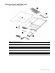
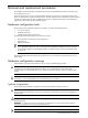
Mechanical parts exploded view Figure 1 Mechanical parts exploded view Table 1 Mechanical spare parts list Item Description Spare Part Number Customer Self Repair 1 Top cover 434437-001 Mandatory 2 Front bezel 434423-001 Mandatory 3 Full-sized riser board assembly 434459-001 Mandatory 4 Low-profile riser board assembly 434458-001 Mandatory 5 Optical drive bay bezel 434436-001 Mandatory 6 Air baffle 434424-001 Mandatory 7 Non-hot-plug hard disk drive (HDD) carrier 434425-001 M
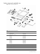
System components exploded view Figure 2 System components exploded view Table 2 System components spare parts list Item Description Spare Part Number 1 Optical drive a) DVD ROM drive b) DVD/CD RW combo drive 436951-001 436952-001 Hot-plug SAS hard drive a) 36 GB b) 72 GB c) 146 GB d) 300 GB 376593-001 376594-001 376595-001 432147-001 Non-hot-plug SATA hard drive a) 80 GB b) 160 GB c) 250 GB d) 500 GB e) 750 GB 373311-001 399968-001 399969-001 404654-001 397377-001 4 Front panel board 434428-00
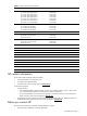
Table 2 System components spare parts list Item Description Spare Part Number 9 Processor a) 1.8 GHz, 68W AMD Opteron b) 1.8 GHz, 95W AMD Opteron c) 2.2 GHz, 68W AMD Opteron d) 2.4 GHz, 68W AMD Opteron e) 2.4 GHz, 95W AMD Opteron f) 2.6 GHz, 95 W AMD Opteron g) 2.
• Product serial number • Product model name and number • Applicable error messages • Add-on boards or hardware • Third-party hardware or software • Operating system type and revision level Illustrated parts catalog 8
Removal and replacement procedures This chapter provides subassembly and module-level removal and replacement procedures for the HP ProLiant DL145 Generation 3 server. Review the specifications of a new component before installing it to make sure it is compatible with the server. When you integrate new components into the system, record its model and serial number and any other pertinent information for future reference.
parts. Do not open for any reason. WARNING! To reduce the risk of injury from electric shock hazards, do not open this enclosure. This symbol on an RJ-45 receptacle indicates a network interface connection. WARNING! To reduce the risk of electric shock, fire, or damage to the equipment, do not plug telephone or telecommunications connectors into this receptacle. This symbol indicates the presence of a hot surface or hot component. If this surface is contacted, the potential for injury exists.
Server warnings and precautions WARNING! Hazardous voltages are present inside the server. Always disconnect AC power from the server and other associated assemblies while working inside the unit. Serious injury may result if this warning is not observed. WARNING! To reduce the risk of personal injury from hot surfaces, allow the hot-plug drives and the internal system components to cool before touching them.
3. Remove the top cover by following the procedure described in the “Opening and closing the server” section on page 12. 4. Follow the ESD precautions listed in the “Electrostatic discharge information” section on page 11 when handling a server component. IMPORTANT: To streamline the configuration process, read through the entire installation and removal procedures first and make sure you understand them before you before you begin.
Figure 3 Removing the top cover 3. Place the top cover in a safe place for reinstallation later. To reinstall the top cover: 1. Perform steps 1 to 3 of the post-installation procedures described on page 12. 2. Reinstall the top cover: a. Place the cover on the chassis approximately 1.25 cm (0.5 in) toward the rear of the unit, then slide the cover forward into place. b. Tighten the captive screw on the rear panel.
Drive bay configuration The server supports three drive bays — two drive bays for hard disk drives and one drive bay for a 9.5-mm optical drive. Go to the HP website at http://www.hp.com/ and refer to the options list for this server model for the latest information on supported hard drives and optical drives.
Optical drive cable routing Figure 6 Optical drive cable routing Item Description Connections 1 Drive power cable • • • P41 on the system board Power connector on the optical drive docking board Power connectors on any installed non-hot-plug SATA hard drives or the hot-plug SATA/SAS backplane, if installed 2 IDE data cable • • J7 on the system board Data connector on the optical drive docking board Removal and replacement procedures 15
Hard drive cable routing Non-hot-plug SATA hard drive cable routing Figure 7 Non-hot-plug SATA hard drive cable routing Item Description Connections 1 Drive power cable • • • P41 on the system board Power connector on each installed non-hot-plug SATA hard drive Power connector on the optical drive docking board, if installed 2 SATA data cables • • P19 or P23 on the system board Data connector on each installed non-hot-plug SATA hard drive Hot-plug SATA/SAS hard drive cable routing Figure 8 shows
Figure 8 Hot-plug SATA/SAS hard drive cable routing with a low-profile controller board Item Description Connections 1 Hot-plug SATA/SAS backplane power • cable • • 2 Hot-plug SATA/SAS cable assembly • • P41 on the system board Power connectors on the hot-plug SATA/SAS backplane Power connector on the optical drive docking board, if installed Data connector on the hot-plug SATA/SAS controller board Data connectors and the LED connector on the hot -plug SATA/SAS backplane Removal and replacement p
Figure 9 Hot-plug SATA/SAS hard drive cable routing with a full-sized controller board Item Description Connections 1 Hot-plug SATA/SAS backplane power • cable • • 2 Hot-plug SATA/SAS cable assembly • • P41 on the system board Power connectors on the hot-plug SATA/SAS backplane Power connector on the optical drive docking board, if installed Data connector on the hot-plug SATA/SAS controller board Data connectors and the LED connector on the hot-plug SATA/SAS backplane Optical drive The optical d
Figure 10 Removing the optical drive bay bezel 3. Install the optical drive docking board: a. Hold the docking board at a slight angle to the chassis, then carefully slide it into place under the nonremovable section of the chassis top cover and on top of the optical drive bay. Be sure not to scratch any docking board components on the non-removable section of the chassis top cover or on the captive thumbscrew on HDD bay 1 beneath the optical drive bay. b.
Figure 13 Installing an optical drive 7. Perform the post-installation procedures described on page 12. Hard drives The server has two HDD bays that support both non-hot-plug SATA hard drives and hot-plug SATA or SAS hard drives. You can add a hard drive to an empty HDD bay by installing an appropriate drive option; servers configured as non-hot-plug systems cannot use hot-plug hard drives, and servers configured as hot-plug systems cannot use non-hot-plug hard drives.
Figure 14 Pre-installed screw locations in the non-hot-plug HDD carrier • Hard drives installed in the server are labeled as drive 1 and drive 2 from left to right when viewed from the front of the server. Figure 15 HDD bay locations Removing a non-hot-plug SATA hard drive If you intend to replace a non-hot-plug SATA hard drive with another non-hot-plug SATA hard drive, use the HDD carrier and screws you remove from the old drive to install the new drive. To remove a non-hot-plug SATA hard drive: 1.
Figure 16 Removing a non-hot-plug SATA hard drive from the chassis 4. Remove the hard drive from the HDD carrier: a. Remove the four mounting screws that secure the hard drive to the HDD carrier. b. Remove the hard drive from the HDD carrier.
If you are installing the new drive in an empty drive bay, use the HDD carrier and mounting screws you removed from that drive bay. b. Secure the hard drive to the HDD carrier with the four mounting screws. c. Slide the hard drive assembly into the chassis. Figure 18 Installing a non-hot-plug SATA hard drive in the HDD carrier and chassis CAUTION: Route the SATA data cables neatly. Follow the bundle of cables along the right side of the chassis.
8. Set up the SATA configuration. For detailed procedures, refer to the Server Support CD or to the operating system documentation. Removing a hot-plug SATA/SAS drive assembly This procedure assumes the hot-plug SATA/SAS backplane is already installed. See the “Installing the hot-plug SATA/SAS backplane” section described on page 26 for more details. To remove a hot-plug SATA/SAS drive assembly from the server: 1.
Figure 21 Aligning the latch on a hot-plug SATA/SAS drive assembly 4. Press the HDD carrier latch inward until it clicks. The latch should pull the hot-plug drive assembly fully into the chassis. The carrier latch should pull against the metal tab on the HDD bay only, not on the front bezel on the chassis. Figure 22 Closing the latch on a hot-plug SATA/SAS drive assembly Replacing a hot-plug SATA or SAS hard drive This procedure assumes the hot-plug SATA/SAS backplane is already installed.
Figure 23 Installing a SATA or SAS hard drive in the hot-plug HDD carrier 4. Perform the procedure in the “Installing a hot-plug SATA/SAS drive assembly” section on page 24 to reinstall the hot-plug drive assembly in the chassis. Installing the hot-plug SATA/SAS backplane To enable hot-plug SATA/SAS drive functionality, you must install a hot-plug SATA/SAS controller board and cabling in addition to the hot-plug backplane.
a. Align the hot-plug backplane between the drive bays and the system fans. The data cable connectors on the backplane should face the rear of the chassis. b. Attach the backplane to the chassis with the screws on each end. Figure 25 Installing the hot-plug backplane 6. Connect and route the new drive power cable included with the option kit: NOTE: Do not reuse the power cable you removed in step 3. a.
8. Perform the post-installation procedures described on page 12. Installing a hot-plug SATA/SAS controller board To enable hot-plug SATA/SAS drive functionality, you must install the hot-plug SATA/SAS backplane in addition to a hot-plug SATA/SAS controller board and cabling. This procedure assumes the backplane is already installed. See the “Installing the hot-plug SATA/SAS backplane” section described on page 26 for more details. To install a hot-plug SATA/SAS controller board: 1.
Figure 27 Connecting the hot-plug SATA/SAS cable assembly to the hot-plug backplane 9. Perform the post-installation procedures described on page 12. System board Refer to the following sections for instructions about how to remove or replace a system board. Removing a system board A server’s system board attaches to the floor of the unit and provides connectivity for all inside components. 1. Perform the pre-installation procedures described on page 11. 2.
Figure 28 Removing the mounting screws from the system board 8. Remove the system board by lifting the end closest to the fans enough to clear the fan bracket and gently sliding the system board toward the front of the chassis. Figure 29 Removing the system board from the chassis Installing a system board This section assumes that the components or cables that would prevent a system board installation are removed or disconnected. 1. Install the system board. a.
Figure 30 Placing the system board on the floor of the chassis b. Slide the system board toward the back of the chassis lowering the front end as it clears the fan bracket. Figure 31 Sliding the system board into the chassis c. Position the system board so that all switches function freely and all connectors seat properly. Figure 32 Positioning the system board connector 2. Install the eleven system board mounting screws.
Figure 33 Installing mounting screws on the system board 3. Follow the instructions for Removing a processor on page 34 and Installing a processor on page 35 to transfer the CPUs from the old system board to the new system board. 4. Reconnect the power supply cables, USB cable, OP panel cable, IDE cable, SATA data cables, and fan cables to the system board. 5. Install the air deflector. a. Place the front edge against the fan bracket. b.
Figure 34 Processor sockets Item Component Code Component 1 U42 AMD Opteron 1207-pin processor 1 socket 2 U55 AMD Opteron 1207-pin processor 2 socket Processor installation guidelines Observe the following important guidelines before performing any of the installation steps listed in the next section: • The processor 1 socket (U42) must always be populated. If no processor is installed in this socket, the system fails to boot, halts during POST, and does not function properly.
Removing a processor 1. Perform the pre-installation procedures described on page 11. 2. Locate the processor you want to remove. 3. Remove the heat sink: a. Loosen the two spring-loaded screws a few threads, alternating back and forth between each screw, to release the heat sink from the processor base. b. Rotate the heat sink back and forth within the available space to break the hold of the thermal grease, then lift the heat sink away from the system board. Figure 35 Removing a heat sink 4.
Figure 36 Removing a processor 5. Place the processor on a static-dissipating work surface or inside an anti-static bag. 6. If you are replacing the processor, continue with the procedure in the “Installing a processor” section described next. Otherwise, protect the empty socket: a. Place the socket retention bracket over the socket. b. Push the socket retention lever back into place. c. Attach the socket cover to the socket retention bracket. d.
Figure 38 Inserting a processor in the processor installation tool 6. Use the processor installation tool to install the new processor into the socket: a. Align the processor installation tool with the processor socket and install the processor. CAUTION: Make sure that the processor is properly aligned in the socket. The corner of the processor marked with a gold triangle should align with the corner of the socket marked on the system board with a triangular symbol. b.
Figure 40 Securing a processor 8. If the heat sink is new, remove the protective cover on the bottom of the heat sink. 9. Install the heat sink: a. Align the heat sink over the processor, then place the heat sink on top of the processor and the heat sink guide rails. CAUTION: Do not overtighten the two spring-loaded screws or they may break off. A maximum torque of 8-in-lb is set for the system. b. Tighten the two spring-loaded screws a few threads, alternating between each screw.
Figure 41 Installing a heat sink 10. Perform the post-installation procedures described on page 12. Memory The system has eight DIMM slots that support up to 16 GB maximum system memory (2 GB in each of the eight DIMM slots).
Figure 42 DIMM slot locations Memory installation guidelines Observe the following important guidelines when installing memory modules: • Use only HP-supported PC2-5300 DDR2 (667 MHz) registered ECC DIMMs in 512 MB, 1 GB, or 2 GB capacities. • The processor 2 socket (U55) must be populated before you can install memory modules in the DIMM5 to DIMM8 slots. • If a second processor is installed, HP does not recommend leaving all processor 2 socket DIMM slots (DIMM5 to DIMM8) empty.
The DIMM slots are designed to ensure proper installation. If you insert a memory module but it does not fit easily into the slot, you may have inserted it incorrectly. Reverse the orientation of the module and insert it again. b. Firmly press the holding clips inward to secure the memory module in place. If the holding clips do not close, the module is not inserted correctly. Figure 43 Installing a memory module 7. Perform the post-installation procedures described on page 12.
6. Perform the post-installation procedures described on page 12. Expansion boards System board expansion slots There are four expansion slots on the system board that support four different PCI riser boards.
NOTE: You cannot install the PCI Express x4 and PCI-X riser boards at the same time. You also cannot install the HTX and PCI Express x16 riser boards at the same time. Expansion board installation guidelines Use only HP-supported expansion boards that meet the following specifications: • HTX: Full-sized, 1 GHz, 16x16 • PCI Express x4: Low-profile • PCI Express x16: Full-sized • PCI-X: Low-profile, 64-bit, 3.
Figure 46 Removing the full-sized assembly Figure 47 Removing the low-profile assembly Installing a riser board assembly 1. Install the assembly in server: a. Align the assembly with the correct slot on the system board and firmly press the assembly into the slot. If you are reinstalling the full-sized assembly, slide the front of the assembly into place with the three retaining tabs on the chassis. The front edge of the assembly should slide underneath the middle retaining tab.
Figure 48 Installing the full-sized assembly Figure 49 Installing the low-profile assembly 2. Perform the post-installation procedures described on page 12. Removing a riser board 1. Perform the procedure described in the “Removing a riser board assembly” section on page 42 to remove the appropriate assembly. 2. If an expansion board is installed in the assembly, perform the procedure in the “Removing an expansion board” section on page 46. 3.
Figure 50 Removing a full-sized riser board Figure 51 Removing a low-profile riser board Installing a riser board 1. 2. Perform the procedure described in the “Removing a riser board assembly” section on page 42 to remove the appropriate assembly. Prepare the assembly for the new riser board: • If no riser board is installed on the assembly, remove the two screws installed on the inside of the vertical side of the assembly.
Figure 52 Installing a full-sized riser board Figure 53 Installing a low-profile riser board 4. Continue with the procedure in the “Installing an expansion board” section on page 46 or the “Installing a riser board assembly” section on page 43 as appropriate. Removing an expansion board 1. Perform the procedure in the “Removing a riser board assembly” section on page 42 to remove the appropriate assembly. 2. Hold the expansion board by the edges and pull it out of the riser board slot. 3.
Figure 54 Removing the full-sized riser board assembly slot cover Figure 55 Removing the low-profile riser board assembly slot cover 3. If an expansion board is installed in the assembly, perform the procedure in the “Removing an expansion board” section on page 46. 4. Remove the expansion board from its protective packaging, handling it by the edges. 5. Verify that the size of the expansion board and its connector are compatible with the assembly.
Figure 56 Installing a full-sized HTX or PCI Express x16 expansion board Figure 57 Installing a low-profile PCI-X or PCI Express x4 expansion board 7. Connect any necessary cables to the expansion board. Refer to the documentation that came with the board. 8. Continue with the procedure in the “Installing a riser board assembly” section on page 43. System battery The HP ProLiant server uses nonvolatile memory that requires a battery to retain system information when power is removed.
Figure 58 System battery location If the server no longer automatically displays the correct date and time, the system battery that provides power to the real-time clock may need to be replaced. Under normal use, the battery life is 5 to 10 years. WARNING! Note the following warnings when replacing the system battery. • Replace the battery with the same type as the battery recommended by HP. Use of another battery may present a risk of fire or explosion.
Figure 59 Removing the system battery 3. Insert a new battery with the positive polarity (+ side) facing up, and ensure that it is seated completely. Ensure the spring latch is in place, and that it holds the battery firmly. Figure 60 Installing the system battery 4. Perform the post-installation procedures described on page 12. System fans The server has three system fans located behind the drive bays. Figure 61 shows the locations of these system fans and the connections to the system board.
Figure 61 System fans If a system fan becomes defective, you must replace the fan to allow the server to operate properly. Removing a system fan 1. Perform the pre-installation procedures described on page 11. 2. Disconnect the 14-pin power cable from the connector on the system board (P22). 3. Remove the power cable guide above the system fans: a. Slide the power cable guide away from the power supply. b. Pull the power cable guide toward the front of the server and place it out of the way.
Figure 62 Removing the power cable guide 4. Remove the system fan you want to replace: a. Disconnect the power cable of the fan from the system board and slide the cable out of the notch in the chassis partition wall. The fan closest to the power supply connects to P47. The middle fan connects to P48. The fan farthest from the power supply connects to P49. b. Loosen the screw holding the fan to the chassis. c. Lift the fan away from the chassis.
Figure 63 Removing a system fan from the chassis Installing a system fan 1. Install the new system fan: a. Place the fan in an open fan location in the chassis. b. Connect the fan power cable to the connector on the system board, and slide the power cable into the notch in the chassis partition wall. The fan closest to the power supply connects to P47. The middle fan connects to P48. The fan farthest from the power supply connects to P49. c. Tighten the screw holding the fan to the chassis.
Figure 65 Installing the power cable guide 3. Connect the 14-pin power cable to the connector on the system board (P22). 4. Perform the post-installation procedures described on page 12. Power supply unit (PSU) Located on the rear panel of the server is a single standard autoranging 650-watt PSU. Figure 66 shows the location of the PSU.
Figure 66 Power supply unit The PSU power cables connect to the P34 and P22 connectors on the system board. Figure 67 shows the PSU power cable routing.
Figure 67 Power supply cable routing WARNING! Take note of the following reminders to reduce the risk of personal injury from electric shock hazards and/or damage to the equipment. • Installation of power supply units should be referred to individuals who are qualified to service server systems and are trained to deal with equipment capable of generating hazardous energy levels. • DO NOT open the power supply unit. There are no serviceable parts inside. Replacing the power supply unit 1.
Figure 68 Removing the power cable guide 4. Disconnect both power supply cables from the system board (P22 and P34). 5. Remove the PSU: NOTE: Keep the two screws you remove in this step for installing the new PSU later. a. Disconnect the AC power cable from the rear of the PSU. b. Remove the two mounting screws on the rear of the PSU. c. Slide the PSU toward the front of the server. d.
Figure 69 Removing the PSU 6. Install the new PSU: CAUTION: Do not overtighten the screws or they may break. A maximum torque of 7 ± 1 is set for the system. a. Place the front of the new PSU in the PSU section of the chassis while raising the rear of the PSU above the power supply mounting pins, then slide the PSU toward the front of the server and over the power supply mounting pins. b.
Figure 70 Installing a PSU 7. Connect the new power supply cables to the system board (P22 and P34). 8. Install the new power cable guide above the system fans: a. Insert the power cable guide into the slots in the rail above the system fans. b. Slide the power cable guide toward the power supply.
Figure 71 Installing the power cable guide 9. Perform the procedure in the “Installing a riser board assembly” section on page 43 to reinstall the fullsized riser board assembly. 10. Perform the post-installation procedures described on page 12.
Diagnostic tools This chapter gives an overview of the diagnostics tools supported by HP ProLiant DL145 Generation 3 server. Overview of available diagnostic tools The following utilities assist in diagnosing problems, testing hardware, and monitoring and managing server operations. Table 3 Diagnostic tools Tool What it is How to run it User Diagnostics A tool to assist testing and/or verifying operation of hardware.
Connectors, buttons, and LEDs This chapter contains illustrations and tables identifying and describing the connectors, buttons, and LED indicators located on the front panel, rear panel, system board, front panel board, and hard drives of the HP ProLiant DL145 Generation 3 server. Connectors and components This section identifies the connectors and components on the front and rear panels of the server, as well as on the system and front panel boards.
Item Icon Component 6 Video port (blue) 7 Serial port 8 PS/2 mouse port (green) 9 PS/2 keyboard port (purple) 10 10/100 Mbps LAN port for IPMI management (RJ-45) 11 USB 2.
Item Component code Component 1 — Broadcom BCM5715 dual gigabit Ethernet controller 2 J3 GbE LAN ports for NIC 1 and NIC 2 3 J5 USB 2.
UID button When performing maintenance on multiple servers in a rack or similar configuration, you can use the UID buttons on the front and rear panels to mark a server by changing the state of the blue UID LEDs. Push either UID button to toggle both UID LEDs on and off. NMI button If the system crashes or stops operating properly, you can use the NMI button (SW3) to mechanically force the server to issue a non-maskable interrupt.
Figure 75 Front panel board components Item Component code Component 1 J1 Power connector 2 J2 6-pin connector for USB 2.0 ports 3 Riser board with USB 2.
Figure 76 Front panel board cable routing Description Connections Front panel board power cable • • J11 on the system board Power connector on the front panel board Front panel board USB cable • • J13 on the system board USB connector on the front panel board CAUTION: Route the front panel board cables neatly. If necessary, secure them using the pre-installed cable clips located on the chassis base.
Figure 77 Front panel LED indicators Item Icon 1 2 Component Status Description UID LED indicator Blue A UID button has been pressed to toggle the indicator on. Off A UID button has been pressed to toggle the indicator off. Off System health is normal. System health LED indicator Solid amber A system threshold has been breached. This may be any of the following: • At least one fan failure has occurred. • A voltage regulator error has occurred.
Item 5 Component Status Description indicator Off No network link detected. NIC activity LED indicator Flashing amber Network data activity was detected within the preceding one second. Off No network data activity was detected within the preceding one second. System board LED indicators The system board has one internal LED, shown in Figure 74 on page 63 (callout 9).
Physical and operating specifications This chapter provides physical and operating specifications for the HP ProLiant DL145 Generation 3 server.
Table 8 Hardware specifications Item Description Power supply unit (PSU) 1U 650-watt PSU System management function IPMI 2.0-compliant with dedicated 10/100 Mbps LAN port for online system health monitoring Thermal solution • • Three system fans for the memory modules, processors, system chipsets, and expansion slots Two PSU fans Table 9 Physical dimensions Item Description System board dimensions Length Width 381 mm (15 in) 325 mm (12.8 in) Server dimensions Height Width Depth 43.2 mm (1.
Table 11 Power supply requirements Item Description Input requirements Input voltage range Normal voltage range Input frequency range 90 to 264 VAC 100 to 240 VAC 47 to 63 Hz Inrush current Less than 100 A peak Memory Table 12 Memory specifications Item Description Size 512 MB, 1 GB, and 2 GB Speed PC2-5300 Type DDR-2 ECC DIMMs Processor Table 13 Processor specifications Item Description Processor type 64-bit AMD Opteron Operating frequency 1.8, 2.0, 2.2, 2.4, and 2.
Index B backplane, hot plug. See hot-plug SATA/SAS backplane battery: installing, 50; location, 49; overview, 48; replacing, 49; warnings and cautions, 49 buttons, 65 C cable guide. See power cable guide cable routing: front panel board, 67; hot-plug SATA/SAS hard drive, 16, 18; non-hot-plug SATA hard drive, 16; optical drive, 15; PSU, 56 CD-ROM drive.
PSU: cable routing, 56; installing, 58; overview, 54, 55; removing, 56; replacing, 56; specifications, 72; warnings, 56 R rear panel: components, 62; LEDs, 68 removal: battery, 49; expansion board, 46; fans, 51; hot-plug SATA/SAS hard drive, 24, 25; memory, 40; non-hot-plug SATA hard drive, 21; power cable guide, 51, 56; processor, 34; processor heat sink, 34; processor socket cover, 35; PSU, 56; riser board, 44; riser board assemblies, 42 removal procedures, 9 replaceable parts, 4 replacement: battery, 4