HP ProLiant DL145 Server Maintenance and Service Guide March 2004 (First Edition) Part Number 361543-001
© Copyright 2004 Hewlett-Packard Development Company, L.P. The information contained herein is subject to change without notice. The only warranties for HP products and services are set forth in the express warranty statements accompanying such products and services. Nothing herein should be construed as constituting an additional warranty. HP shall not be liable for technical or editorial errors or omissions contained herein.
Contents About This Guide Audience Assumptions..................................................................................................................................v Technician Notes...........................................................................................................................................v Where to Go for Additional Help.................................................................................................................vi Telephone Numbers ...........
Contents Video Board .............................................................................................................................................2-26 32-Bit PCI Riser Board ............................................................................................................................2-27 IPMI Base Management Controller .........................................................................................................2-28 Signal Interface Board ...........................
About This Guide This maintenance and service guide can be used for reference when servicing HP ProLiant DL145 servers. WARNING: To reduce the risk of personal injury from electric shock and hazardous energy levels, only authorized service technicians should attempt to repair this equipment. Improper repairs can create conditions that are hazardous. Audience Assumptions This guide is for service technicians.
About This Guide CAUTION: To properly ventilate the system, you must provide at least 7.6 cm (3.0 in.) of clearance at the front and back of the server. CAUTION: The computer is designed to be electrically grounded (earthed). To ensure proper operation, plug the AC power cord into a properly grounded AC outlet only. NOTE: Any indications of component replacement or printed wiring board modifications may void any warranty.
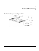
1 Illustrated Parts Catalog Mechanical Components Exploded View Figure 1-1: Mechanical components exploded view HP ProLiant DL145 Server Maintenance and Service Guide 1-1
Illustrated Parts Catalog Mechanical Components Spare Parts List Table 1-1: Mechanical Components Spare Parts List 1-2 Item Description Spare Part Number 1 Power supply 361620-001 2 DVD adapter board 364313-001 3 DVD drive (optional) 361622-001 4 40-GB ATA 7200 NHP hard drive 232008-001 5 Drive tray 361640-001 HP ProLiant DL145 Server Maintenance and Service Guide
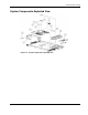
Illustrated Parts Catalog System Components Exploded View Figure 1-2: System components exploded view HP ProLiant DL145 Server Maintenance and Service Guide 1-3
Illustrated Parts Catalog System Components Spare Parts List Table 1-2: System Components Spare Parts List Item Description Spare Part Number 1 PCI-X 133 riser board 361618-001 2 COM1/IPMI cable 364317-001 3 System board 361614-001 4 VGA video board 364314-001 5 IPMI Base Management Controller 361615-001 6 32 bit PCI riser board 361619-001 7 Signal interface board 361617-001 8 Processor 8a Processor, 1.6 GHz 361956-001 8b Processor, 1.8 GHz 361957-002 8c Processor, 2.
2 Removal and Replacement Procedures You need the following items for some procedures: • Phillips screwdriver Safety Considerations Before performing service procedures, review the following safety information. Electrostatic Discharge A discharge of static electricity can damage static-sensitive devices or micro-circuitry. Proper packaging and grounding techniques are necessary precautions to prevent damage.
Removal and Replacement Procedures Server Warnings and Cautions WARNING: Do not exceed the level of repair specified in the procedures in the product documentation. All troubleshooting and repair procedures are detailed to allow only subassembly or module-level repair. Because of the complexity of the individual boards and subassemblies, do not attempt to make repairs at the component level or to make modifications to any printed wiring board. Improper repairs can create a safety hazard.
Removal and Replacement Procedures Powering Up the Server To power up the server, press the Power button. Powering Down the Server WARNING: To reduce the risk of personal injury, electric shock, or damage to the equipment, remove the power cord to remove power from the server. The front panel Power button does not completely shut off system power. Portions of the power supply and some internal circuitry remain active until AC power is removed. 1. Back up the server data. 2.
Removal and Replacement Procedures Removing the Server from the Rack Press the side rail tabs to release the server from the rack rails.
Removal and Replacement Procedures Removing the Access Panel WARNING: Pressing the Power button does not remove power from all areas of the server. Portions of the power supply and some internal circuitry remain active until the AC power cord is removed. WARNING: To reduce the risk of personal injury from hot surfaces, allow the internal system components to cool before touching. CAUTION: Electrostatic discharge can damage electronic components.
Removal and Replacement Procedures Memory Options The server provides double data rate (DDR) synchronous dynamic RAM (SDRAM) that can improve memory clock speed to at least 333-MHz. It activates output on both the rising and falling edge of the system clock rather than on just the rising edge, potentially doubling output.
Removal and Replacement Procedures Table 2-1: DIMM and Processor Locations continued Item Description Bank 2 DIMM slot 4 Bank 1B 3 DIMM slot 3 Bank 1B 4 DIMM slot 2 Bank 1A 5 DIMM slot 1 Bank 1A 6 Processor socket 1 7 Processor socket 2 8 DIMM slot 1 Bank 2A 9 DIMM slot 2 Bank 2A 10 DIMM slot 3 Bank 2B 11 DIMM slot 4 Bank 2B 12 Processor Power Module 2 13 System battery HP ProLiant DL145 Server Maintenance and Service Guide 2-7
Removal and Replacement Procedures To remove a DIMM: 1. Power down the server. Refer to “Powering Down the Server” ea rlier in this chapter. 2. Extend the server from the rack. Refer to “Extending the Server from the Rack” earlier in this chapter. 3. Remove the access panel. Refer to “R emoving the Access Panel” earlier in this chapter. 4. Remove the DIMM. Figure 2-5: Removing a DIMM Reverse steps to replace a DIMM.
Removal and Replacement Procedures Processors The server supports up to two processors. CAUTION: Processor socket 1 and processor power module (PPM) slot 1 must be populated at all times or the server will not function properly. CAUTION: If upgrading processor speed, update the system ROM before installing the processor. IMPORTANT: Mixing processor speeds and cache sizes is not supported. To remove a processor: 1. Power down the server. Refer to “Powering Down the Server” ea rlier in this chapter. 2.
Removal and Replacement Procedures 5. Remove the processor. Figure 2-7: Removing a processor Reverse the steps to replace a processor.
Removal and Replacement Procedures Processor Power Module (PPM) To remove a PPM: 1. Power down the server. Refer to “Powering Down the Server” ea rlier in this chapter. 2. Extend the server from the rack. Refer to “Extending the Server from the Rack” earlier in this chapter. 3. Remove the access panel. Refer to “R emoving the Access Panel” earlier in this chapter. 4. Remove the PPM. Figure 2-8: Removing a PPM Reverse the steps to replace a PPM.
Removal and Replacement Procedures DVD Drive To remove the DVD drive and the DVD adapter board: 1. Power down the server. Refer to “Powering Down the Server” ea rlier in this chapter. 2. Extend the server from the rack. Refer to “Extending the Server from the Rack” earlier in this chapter. 3. Remove the access panel. Refer to “R emoving the Access Panel” earlier in this chapter. 4. Remove the retainer clip. Figure 2-9: Removing retainer clip from the DVD drive 5.
Removal and Replacement Procedures 6. Remove the DVD adapter board from the DVD drive. Figure 2-11: Removing the DVD adapter board from the DVD drive Reverse the steps to replace the DVD drive and the DVD adapter board.
Removal and Replacement Procedures Hard Drives Removing the Drive in Drive Bay 1 To remove a hard drive from bay 1: 1. Power down the server. Refer to “Powering Down the Server” ea rlier in this chapter. 2. Extend the server from the rack. Refer to “Extending the Server from the Rack” earlier in this chapter. 3. Remove the access panel. Refer to “R emoving the Access Panel” earlier in this chapter. 4. Remove the drive tray screw. 5. Disconnect the drive cables from the server. 6.
Removal and Replacement Procedures 7. Disconnect the cables from the drive. Figure 2-13: Disconnecting the cables from the drive 8. Remove the drive from the drive tray. Figure 2-14: Removing the drive from the drive tray IMPORTANT: To simplify the installation of the drive, connect the cables to the drive before installing the drive in the server. Reverse the steps to replace a disk drive.
Removal and Replacement Procedures Removing the Drive in Drive Bay 2 To remove a hard drive from bay 2: 1. Power down the server. Refer to “Powering Down the Server” ea rlier in this chapter. 2. Extend the server from the rack. Refer to “Extending the Server from the Rack” earlier in this chapter. 3. Remove the access panel. Refer to “R emoving the Access Panel” earlier in this chapter. 4. Remove the DVD drive or media bay blank.
Removal and Replacement Procedures 8. Remove the drive from the drive tray. Figure 2-16: Removing the drive from the drive tray IMPORTANT: To simplify the installation of the drive, connect the cables to the drive before installing the DVD drive and securing the drive tray to the server. Reverse the steps to replace a disk drive.
Removal and Replacement Procedures PCI-X Riser Cage Removing the PCI-X Riser Cage To remove the PCI-X riser cage: 1. Power down the server. Refer to “Powering Down the Server” ea rlier in this chapter. 2. Extend the server from the rack. Refer to “Extending the Server from the Rack” earlier in this chapter. 3. Remove the access panel. Refer to “R emoving the Access Panel” earlier in this chapter. 4. Remove the PCI-X riser cage.
Removal and Replacement Procedures Removing the PCI-X Expansion Board To remove a PCI-X expansion board: 1. Power down the server. Refer to “Powering Down the Server” ea rlier in this chapter. 2. Extend the server from the rack. Refer to “Extending the Server from the Rack” earlier in this chapter. 3. Remove the access panel. Refer to “R emoving the Access Panel” earlier in this chapter. 4. Remove the PCI-X riser cage. Refer to “R emoving the PCI-X Riser Cage” earlier in this chapter. 5.
Removal and Replacement Procedures Removing the COM1/IPMI Connector To remove the COM1/IPMI connector: 1. Power down the server. Refer to “Powering Down the Server” ea rlier in this chapter. 2. Extend the server from the rack. Refer to “Extending the Server from the Rack” earlier in this chapter. 3. Remove the access panel. Refer to “R emoving the Access Panel” earlier in this chapter. 4. Remove the PCI-X riser cage. Refer to “R emoving the PCI-X Riser Cage” earlier in this chapter. 5.
Removal and Replacement Procedures 6. Disconnect the other end of the COM1/IPMI connector from the server. Figure 2-20: Disconnecting the COM1/IPMI connector from the server Reverse the steps to replace the COM1/IPMI connector.
Removal and Replacement Procedures Removing the PCI-X Riser Board To remove the PCI-X riser board: 1. Power down the server. Refer to “Powering Down the Server” ea rlier in this chapter. 2. Extend the server from the rack. Refer to “Extending the Server from the Rack” earlier in this chapter. 3. Remove the access panel. Refer to “R emoving the Access Panel” earlier in this chapter. 4. Remove the PCI-X riser cage. Refer to “R emoving the PCI-X Riser Cage” earlier in this chapter. 5.
Removal and Replacement Procedures Power Supply To remove a power supply: 1. Power down the server. Refer to “Powering Down the Server” ea rlier in this chapter. 2. Extend the server from the rack. Refer to “Extending the Server from the Rack” earlier in this chapter. 3. Remove the access panel. Refer to “R emoving the Access Panel” earlier in this chapter. 4. Remove the PCI-X riser cage. Refer to “R emoving the PCI-X Riser Cage” earlier in this chapter. 5. Disconnect the power cord from the power supply.
Removal and Replacement Procedures Fans To replace the fans 1. Power down the server. Refer to “Powering Down the Server” ea rlier in this chapter. 2. Extend the server from the rack. Refer to “Extending the Server from the Rack” earlier in this chapter. 3. Remove the access panel. Refer to “R emoving the Access Panel” earlier in this chapter. 4. Disconnect the fans.
Removal and Replacement Procedures 5. Remove the fans. Figure 2-24: Removing the fans Reverse the steps to replace the fans.
Removal and Replacement Procedures Video Board To remove the video board: 1. Power down the server. Refer to “Powering Down the Server” ea rlier in this chapter. 2. Extend the server from the rack. Refer to “Extending the Server from the Rack” earlier in this chapter. 3. Remove the access panel. Refer to “R emoving the Access Panel” earlier in this chapter. 4. Remove the video board. Figure 2-25: Removing the video board Reverse the steps to replace the video board.
Removal and Replacement Procedures 32-Bit PCI Riser Board To remove the 32-bit PCI riser board: 1. Power down the server. Refer to “Powering Down the Server” ea rlier in this chapter. 2. Extend the server from the rack. Refer to “Extending the Server from the Rack” earlier in this chapter. 3. Remove the access panel. Refer to “R emoving the Access Panel” earlier in this chapter. 4. Remove the video board. Refer to “Vid eo Board” earl ier in this chapter. 5. Remove the 32-bit PCI riser board.
Removal and Replacement Procedures IPMI Base Management Controller To remove the IPMI Base Management Controller: 1. Power down the server. Refer to “Powering Down the Server” ea rlier in this chapter. 2. Extend the server from the rack. Refer to “Extending the Server from the Rack” earlier in this chapter. 3. Remove the access panel. Refer to “R emoving the Access Panel” earlier in this chapter. 4. Remove the video board. Refer to “Vid eo Board” earl ier in this chapter. 5.
Removal and Replacement Procedures Signal Interface Board To remove the signal interface board: 1. Power down the server. Refer to “Powering Down the Server” ea rlier in this chapter. 2. Extend the server from the rack. Refer to “Extending the Server from the Rack” earlier in this chapter. 3. Remove the access panel. Refer to “R emoving the Access Panel” earlier in this chapter. 4. Remove the signal interface board.
Removal and Replacement Procedures Front Panel Board To remove the front panel board: 1. Power down the server. Refer to “Powering Down the Server” ea rlier in this chapter. 2. Extend the server from the rack. Refer to “Extending the Server from the Rack” earlier in this chapter. 3. Remove the access panel. Refer to “R emoving the Access Panel” earlier in this chapter. 4. Disconnect all cables from the front panel board. 5. Remove the signal interface board.
Removal and Replacement Procedures System Battery WARNING: This server contains an internal lithium manganese dioxide or vanadium pentoxide battery. A risk of fire and burns exists if the battery is not handled properly. To reduce the risk of personal injury: • Do not attempt to recharge the battery. • Do not expose to temperatures higher than 60°C (140°F). • Do not disassemble, crush, puncture, short external contacts, or dispose of in fire or water.
Removal and Replacement Procedures 5. Remove the existing battery. Figure 2-30: Removing a battery 6. Install the new battery. 7. Install the access panel. 8. Restore the server to its operating position in the rack. 9. Reconfigure the server using the BIOS Setup Utility if the settings were lost. Refer to HP ProLiant DL145 Server User Guide for more information on the BIOS Setup Utility.
Removal and Replacement Procedures System Board To remove the system board: 1. Power down the server. Refer to “Powering Down the Server” ea rlier in this chapter. 2. Extend the server from the rack. Refer to “Extending the Server from the Rack” earlier in this chapter. 3. Remove the access panel. Refer to “R emoving the Access Panel” earlier in this chapter. 4. Remove the PCI-X riser cage. 5. Remove the processors. 6. Remove the Processor Power Modules. 7. Remove the DIMMs. 8. Remove the video board. 9.
3 Diagnostic Tools Table 3-1: Diagnostic Tools Tool Description How to run the tool Insight Diagnostics Insight Diagnostics tests and verifies operation of HP hardware. If Diagnostics finds a hardware failure, it isolates the replaceable part, if possible. Insight Diagnostics also gathers critical hardware and software information on ProLiant servers. Diagnostics can be downloaded by following the support link on the product website at www.hp.com/support.
4 Server Component Identification Front Panel Components Figure 4-1: Front panel components Table 4-1: Front Panel Components Item Description Status 1 LAN activity LED On = Network link Flashing = Network link and activity Off = No link to network 2 System health LED Off = Normal On = System degraded 3 Disk drive activity LED On = Drive activity Flashing = High drive activity Off = No drive activity continued HP ProLiant DL145 Server Maintenance and Service Guide 4-1
Server Component Identification Table 4-1: Front Panel Components continued Item Description Status 4 Power LED On = Power on Off = Power off 5 Power button 6 USB port 7 Hard drive bay 1 8 Hard drive bay 2 9 Media bay Rear Panel Connectors Figure 4-2: Rear panel connectors Table 4-2: Rear Panel Connectors 4-2 Item Description Item Description 1 Mouse 5 Out of Band Management NIC 2 Keyboard 6 NIC 2 3 Video 7 NIC 1 4 USB 8 COM1/IPMI HP ProLiant DL145 Server Maintenance
Server Component Identification Rear Panel LEDs Figure 4-3: Rear Panel LEDs Table 4-3: Rear Panel LEDs Item Description LED Color Status 1 Aux Power LED Amber On = Aux power present Off = No Aux power 2 LAN Link LED Green Green = 1 GB connection Off = no link to network Red Red = 10/100 MB connection Off = no link to network 3 LAN Activity LED Amber HP ProLiant DL145 Server Maintenance and Service Guide On or flashing = network activity Off = no network activity 4-3
Server Component Identification System Board Components Figure 4-4: System board components Table 4-4: System Board Components 4-4 Item Description 1 PCI-X riser board slot 2 NVRAM Battery 3 IPMI Base Management Controller 4 Video board 5 J9 CMOS jumper 6 Processor socket 2 7 Memory banks 2A and 2B 8 Processor power module slot 2 9 Processor power module slot 1 10 Memory banks 1A and 1B 11 Processor 1 (boot processor) HP ProLiant DL145 Server Maintenance and Service Guide
Server Component Identification J9 CMOS Jumper Figure 4-5: J9 CMOS Jumper To clear CMOS: 1. Back up the server data. 2. Shut down the operating system as directed by the operating system documentation. 3. Press the Power button to power down the server. When the server powers down, the system power LED turns off. 4. Disconnect the power cord. 5. Set the J9 CMOS jumper to Clear and hold in position for 3 seconds. 6. Reset the J9 CMOS jumper to Set. 7. Connect the power cord. 8. Power up the system. 9.
5 Troubleshooting This chapter provides specific troubleshooting information for the server. Use it to diagnose server startup and installation problems. For information on LEDs, switch settings, and jumpers, refer to Chapter 4, “Server Component Identification.” If the Server Does Not Start This section provides step-by-step instructions when encountering the most common problems during the initial Power-On Self-Test (POST).
Troubleshooting 4. Be sure that a normal power up sequence has occurred to confirm that the system meets the minimal hardware requirements and is powered up under normal operation. The system has powered up successfully if: a. The front panel power LED turns on. b. The fans start up. c. The monitor displays messages regarding server initialization. d. The operating system loads to complete the boot process. If the problem persists, continue with the section, “Diagnosis Steps,” in this chap ter.
Troubleshooting WARNING: To reduce the risk of electric shock or damage to the equipment, before opening access panels to reseat components, power down the server, and then disconnect the power cord. NOTE: For LED locations and functions, refer to Chapter 4, “Server Component Identification.” Table 5-2: Front Panel Power LED Is Not On Possible Reasons The Next Step There is no AC power connection. 1. The power button was not firmly pressed. 2. 3. 4. A processor has failed or is not properly seated.
Troubleshooting WARNING: To reduce the risk of electric shock or damage to the equipment, before opening access panels to reseat components, power down the server, and then disconnect the power cord. Table 5-3: Server Does Not Have Video Possible Reasons The Next Step Video cable may not be properly connected. 1. If an optional video board was installed, the monitor cable may not be correctly connected. Be sure that the monitor has power and that the monitor cable is securely connected.
Troubleshooting Problems After Initial Startup After the server has passed POST, errors may still be encountered, such as an inability to load the operating system. Use Table 5-5 to troubleshoot server installation problems that occur after the initial startup. For updated information on supported operating systems go to http://hp.com/go/supportos NOTE: If the server is rebooting repeatedly, be sure that the system is not restarting due to a Watchdog Timer power up caused by another problem.
6 Specifications This chapter provides operating and performance specifications for the server. Table 6-1: Server Specifications Feature Units Dimensions Height 4.3 cm (1.7 in) Depth 71.1 cm (28 in) Width 43.1 cm (17.0 in) Weight 13.6 kg (30 lb) International input requirements Rated input voltage 180 V to 264 V Rated input frequency 47 Hz to 63 Hz Rated input current 1 AMP @240 VAC U.S.
Index 3 D 32-Bit PCI riser board, removing 2-27 diagnosis steps 5-2 DIMMs 4-4 DIMMs, removing 2-8 disk drive activity LED 4-1 DVD adapter board, removing 2-13 DVD drive, removing 2-12 A AC power supply See power supply access panel opening 2-5 access panel, removing 2-5 AUX power LED 4-3 B battery installing 2-31, 2-32 replacement requirements 2-31 warning 2-31 battery, location 4-4 battery, removing 2-32 bay hard drive bay 4-2 media bay 4-2 BIOS Setup Utility, described 3-1 C clearing CMOS 4-5 CMOS
Index I P Insight Diagnostics, described 3-1 Insight Diagnostics, utility 3-1 Insight Manager See Systems Insight Manager installing battery 2-31, 2-32 system battery 2-31, 2-32 IPMI Base Management Controller 4-4 IPMI Base Management Controller, removing 2-28 part numbers mechanical components 1-2 system components 1-4 PCI-X expansion board, removing 2-19 PCI-X riser board, removing 2-22 PCI-X riser cage, removing 2-18 PCI-X slot 4-4 power button 4-2 power LED 4-2 power supply, removing 2-23 powering u
Index requirements battery replacement 2-31 ROMPaq Utility, described 3-1 S server diagnosis steps 5-2 dimensions 6-1 does not start 5-1 mechanical components 1-2 powering up 2-3 specifications 6-1 system components 1-4 troubleshooting resourcesps 5-5 warnings and cautions 2-2 weight 6-1 server specifications 6-1 Setup Utility, BIOS 3-1 signal interface board, removing 2-29 spare part numbers mechanical components 1-2 system components 1-4 static electricity, prevention 2-1 system battery installing 2-31,