HP ProLiant DL165 Generation 5 Server Software Configuration Guide Part number 449864-002 Second edition December 2011
Legal notices © Copyright 2007, 2011 Hewlett-Packard Development Company, L.P. The information contained herein is subject to change without notice. The only warranties for HP products and services are set forth in the express warranty statements accompanying such products and services. Nothing herein should be construed as constituting an additional warranty. HP shall not be liable for technical or editorial errors or omissions contained herein. Microsoft and Windows are U.S.
Contents System BIOS configuration .................................................................................................................... 5 System BIOS overview ................................................................................................................................. 5 AMIBIOS software ...................................................................................................................................... 5 AMIBIOS Setup Utility .............................
Server management............................................................................................................................ 58 Pre- and post-installation procedures ........................................................................................................... 58 Pre-installation procedures .................................................................................................................... 58 Post-installation procedures .........................................
System BIOS configuration System BIOS overview A Basic Input/Output System, or BIOS, is a set of programs permanently stored in an EEPROM chipset (U70) located on the system board. These programs serve as an interface between the server’s hardware components and its operating system. This ProLiant server features the AMIBIOS software— a ROM BIOS-based diagnostic tool that monitors system activity and performs constant hardware testing to ensure proper system operation.
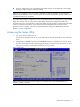
• When a configuration error is detected by the system and you are prompted by a "Run Setup" message to make changes to the BIOS settings. NOTE: If you repeatedly receive “Run Setup” messages, the battery located on the system board (XBAT1) may be defective. In this case, the system cannot retain configuration values in CMOS. Ask a qualified technician for assistance. The Setup Utility loads the configuration values in a battery-backed nonvolatile memory called CMOS RAM.
Navigating through the Setup Utility Use the keys listed in the legend bar on the bottom of the Setup screen to access the various menu and submenu screens of the Setup Utility. Figure 1 in the previous section shows the legend bar at the bottom of the Main menu. Table 1 Setup Utility navigation keys Setup Utility navigation keys lists these legend keys and their respective functions. Table 1 Setup Utility navigation keys Key Function ← and → Move between selections on the menu bar.
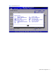
Figure 2 General Help Screen System BIOS configuration 8
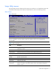
Setup Utility menus The Setup Utility menu bar displays the five primary menu selections. For detailed information and screenshots of these Setup menus and their related submenus, refer to the following sections. Main Menu Figure 3 Main Menu NOTE: The time is in 24-hour format. For example, 5:30 A.M. appears as 05:30:00, and 5:30, P.M. as 17:30:00. If you clear CMOS, setup time and date values will be 00:00:00 and 02/29/2006.
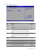
Boot Settings Configuration submenu Figure 4 Boot Settings Configuration submenu Table 3 Boot Settings Configuration submenu fields Field Description Options BIOS Summary Display Set this value to not allow display hardware summary screen before booting the OS. Disabled Set this value to allow display s hardware summary screen before booting the OS. Enabled Set this value to allow the Number Lock on the keyboard to be enabled automatically when the computer system is boot up.
Advanced menu Figure 5 Advanced menu NOTE: The CPU Configuration setup screen varies depending on the installed processor. Table 4 Advanced menu fields Field Description CPU Configuration You can use this screen to select options for the CPU Configuration Settings. Use the up and down keys to select an item. Use the and keys to change the value of the selected option. A description of the selected item appears on the right side of the screen.
Table 4 Advanced menu fields Field Description Event Log Configuration These items specify event log configuration. From this configuration screen, press to the submenu to view Event log ,mark all events as read, clean event log. Use the up and down keys to select an item. Use the and keys to change the value of the selected option. The setting is described on the following pages. IPMI Configuration Select this option and press to access the submenu.
CPU Configuration submenu Figure 6 CPU Configuration submenu Table 5 CPU Configuration submenu fields Field Description Options Runtime Legacy PSB Set this value to allow the generation of power state blocks for use of PowerNow drive in a single core system. Disabled Set this value to prevent the generation of power state block for Enabled use of PowerNow drive in a single core system.
Table 6 IDE Configuration submenu fields Field Description Options Onboard PCI IDE Controller Set this value to allow the computer system to detect the Primary and Secondary IDE channels. This includes both the Primary Master, Primary Slave, Secondary Master, and Secondary Slave. Both Set this value to allow the computer system to detect only the Primary Primary IDE channel. This includes both the Primary Master and the Primary Slave.
SuperIO Configuration submenu Figure 8 SuperIO Configuration submenu Table 7 SuperIO Configuration submenu fields Option Description Disabled Set this value to prevent the serial port from accessing any system resources. When this option is set to Disabled, the serial port physically becomes unavailable 3F8/IRQ4 Set this value to allow the serial port to use 3F8 as its I/O port address and IRQ 4 for the interrupt address. This is the default setting.
S-ATA Configuration submenu Figure 9 S-ATA Configuration submenu Table 8 S-ATA Configuration submenu fields Field Description Options HT1000 S-ATA Set this value to enabled HT1000 S-ATA controller. Enabled Set this value to prevent the generation of power state block for use of PowerNow drive in a single core system. Disabled Set this value to S-ATA mode. S-ATA Set this value to P-ATA mode. P-ATA Set this value to enabled INT13 support. Enabled Set this value to disabled INT13 support.
ACPI Configuration submenu Figure 10 ACPI Configuration submenu Table 9 ACPI Configuration submenu fields Field Description Options ACPI Version Features Set this value to enabled ACPI Version Features Enabled Set this value to disabled ACPI Version Features Disabled Set this value to enabled ACPI OEMB table Enabled Set this value to disabled ACPI OEMB table Disabled Set this value to disabled Headless mode Disabled Set this value to enabled Headless mode Enabled AMI OEMB table Headless mo
Event Log Configuration submenu Figure 11 Event Log Configuration submenu Table 10 Event Log Configuration submenu fields Field Description View Event log The option specifies View event log, it will display the event log. You can read some system information. Mark all events as read The option specifies mark all events as read, it will display the dialog windows to allow you mark all events as read now. There are you can select ok to mark all events as read now.
IPMI Configuration submenu Figure 12 IPMI Configuration submenu Table 11 IPMI Device Configuration submenu fields Field Description SEL Configuration Select SEL configuration in the left frame of the screen to go to the sub menu for that item. Then you can press Enter to enter its sub-menu. You can display an about SEL Configuration option by highlighting it using the keys.
Figure 13 SEL Configuration submenu Table 12 SEL Configuration submenu fields Field Description View BMC System Event Log The option specifies BMC system event log. Select this option and press to access the submenu where you can view the contents of System Event log. Clear BMC System Event Log The option specifies clear system event log. If the BMC Event log is full, you can choose this item to clear out the BMC Event log.
Figure 14 Serial Port Configuration submenu Table 13 Serial Port Configuration submenu fields Field Description Options Serial Port Assignment This setting will assign the serial port connector to the system. This is the default setting. System This setting will assign the serial port connector to the BMC (Baseboard management controller). BMC Serial Port Switching This setting allows the Serial port switch between system and BMC. This is the default setting.
Figure 15 LAN Configuration submenu Table 14 LAN Configuration submenu fields Field Description Options Share NIC Mode Setting this value will prevent support from share NIC mode. Disabled Setting this value will allow support share NIC mode.(Disabled the KVM). Enabled Setting this value will allow dynamic IP assignment. Enabled Setting this value will allow manual IP assignment.
Figure 16 Watchdog Configuration submenu Table 15 Watchdog Configuration submenu fields Field Description Options POST Watchdog Timer Action Set this value to allow BMC to reset if the operating system crashes or hangs. Reset System Disabling this option disables any BMC action if OS crashes or hangs. This is the default setting. Disabled Set this value to allow BMC to power down if the operating system crashes or hangs.
Figure 17 Hardware health information submenu Console Redirection submenu Figure 18 Console Redirection submenu Table 16 Console Redirection submenu fields Field Description Options Console Redirection Setting this value will allow configure the serial port. Enabled Setting this value will prevent configure the serial port.
USB Configuration submenu Figure 19 USB Configuration submenu NOTE: When you install USB storage, there is display USB Mass Device Configuration item. From this item, you can get some information about the device, some information you can configure if you need. Table 17 USB Configuration submenu fields Field Description Options USB Controller This setting allows the use of the USB function. This is the default setting. Enabled This setting makes the onboard USB function unavailable. Disabled USB 2.
Boot Menu Figure 20 Boot Menu Table 18 Boot Menu fields Field Description Boot Device Priority Use this screen to specify the order in which the system checks for the device to boot from. To access this screen, select Boot Device priority on the Boot setup screen and press ; the following screen displays. Removable Drives Use this screen to removable drives in the system. To access this screen, select removable drives on the Boot Setup screen and press .
Boot Device Priority submenu To change the boot order, select a boot category type such as Hard disk drives, Removable media or ATAPI CD ROM devices from the boot menu. For example, if the 1st boot device is set to Hard disk drives, then BIOS will try to boot to hard disk drives first. Figure 21 Boot Device Priority submenu NOTE: When you select a boot category from the boot menu, a list of devices in that category appears.
Security menu The Security menu allows users to set an administrator password. When entered, this password allows the user to access and change all settings in the Setup Utility. If the password has been installed, Installed displays; if not, Not Installed displays. Figure 23 Security menu To set an administrator password: 1. In the Security menu screen, in the Change Administrator Password field, press Enter. The Enter New Password window displays. Figure 24 Enter New Password 2.
Figure 25 Confirm New Password 3. Type the same password in the Confirm New Password box to verify the first entry, and then press Enter. The Password Installed windows displays. Press OK to finish. Figure 26 Password installed 4. Press F10 to save the password and close the Setup Utility. Setup automatically changes the Administrator Password field to Installed.
To change the administrator password: 1. In the Security menu screen, in the Change Administrator Password field, press Enter. The Enter New Password window displays. Type a new password in the Enter New Password box. 2. Type the same password in the Confirm New Password box to verify the first entry, then press Enter. The Password Installed OK windows display; press Enter to finish. : To clear the administrator password: 1.
Exit menu The Exit menu displays several options on how to quit the Setup Utility. Select any of the exit options, and then press Enter. Figure 28 Exit menu Table 20 Exit menu fields Option Description Save Changes and Exit Save the changes made and exit the Setup Utility Discard Changes and Exit Discard the changes and exit the setup utility Discard Changes Discard the changes in the utility Load Option Default Loads the default settings for all BIOS setup fields.
BIOS Summary Display screen The BIOS Summary Displays basic and important information about the current server configuration and is necessary for troubleshooting and may be required when asking for technical support.
Recording custom Setup values Write down the settings from the Setup Utility and keep them in a safe place. If the custom values ever need restoring (after clearing CMOS, for example), you must run the Setup Utility and enter these custom settings again. Having a record of these custom settings makes this much easier. Loading system defaults If the system fails after you make changes in the Setup menus, reboot the server, enter Setup, and load the system default settings to correct the error.
These diagnostics, which reside in the BIOS ROM, isolate server-related logic failures and indicate the board or component that needs to be replaced, as indicated by the error messages. Most server hardware failures are accurately isolated during POST. The number of tests displayed depends on the configuration of the server.
Table 21 POST Error Messages Error code Error message Description/corrective action 0250 System battery is dead Replace and run SETUP The CMOS clock battery indicator shows the system battery is dead. 1 Replace the system battery following the procedures in the HP ProLiant 2 0251 System CMOS checksum bad - Default configuration used DL165 Generation 5 Server Maintenance and Service Guide. Run Setup to reconfigure the system.
POST-related troubleshooting Perform the following procedures when POST fails to run, error messages are displayed, or beep codes are emitted. If the POST failure is during a routine bootup, verify the following conditions: • • • All external cables and power cables are firmly plugged in. • • • • • The monitor's contrast and brightness settings are correct. The power outlet to which the server is connected is working. The server and monitor are both turned on.
Reprogramming the BIOS after the ROM disaster If the BIOS becomes corrupted, use the crisis recovery USB key to reprogram the BIOS. To reprogram the BIOS: 1. Perform the pre-installation procedures. 2. Connect a HP crisis recovery USB key to one of the USB ports on the server. 3. Power on the system and wait for about 10 Minutes. 4. Reboot the system to check the system can boot normally or not.
NOS installation Supported NOS Table 22 Supported network operating systems (NOS) NOS Version On-line information site Microsoft Windows Microsoft Windows Server 2003—Enterprise, Standard, and Web Editions Microsoft Windows Server 2003 R2—Enterprise, Standard, and Web Editions Microsoft Windows Server 2003 for 64-bit Microsoft World Wide Web access: www.microsoft.com Microsoft Product Support Services: http://support.microsoft.
• Note that most NOS installations remove all data from the hard disk on which they are installed. If you want to use additional hard disk drives to access existing data in the new server, HP recommends that you install and configure any of these hard drives after completing the NOS installation. • If you want to recycle used hard drives, use a utility such as fdisk to erase all data and partitions from that particular hard drive.
1. Insert one blank, formatted 3.5" diskette into the floppy drive. 2. Insert the Support CD into the optical media drive. By default, the Support CD automatically runs and displays the Welcome page. However, if this does not occur, double-click the Startup.htm file located on the root directory of the Support CD. 3. Follow the on-screen instructions to create the Windows NOS driver diskette. 4. Label, date, and save the driver diskette as HP disk [Windows NOS version]. Section 2.
At the Welcome to Windows dialog box, press Ctrl-Alt-Del, then log on as Administrator. If you have successfully installed the Windows NOS, the Configure Your Server wizard launches. Close this window to postpone the customization of the server until all of the installation steps are completed. You can open the Configure Your Server wizard at any point by clicking Start | Programs |Administrative Tools | Configure Your Server. Section 3.
2. Click the HP ProLiant DL165 Generation 5 server drivers for chipset, Network, and Video link. 3. Select the embedded VGA driver for the Windows [NOS version] option. The File Download dialog box displays. 4. Click Open to download the driver. The Security Warning dialog box displays. 5. Click Yes. The installation menu for the selected driver is displayed. 6. Follow the on-screen instructions to install the embedded VGA driver. 7. After completing the installation, reboot the server.
• Basic drives are used to create primary or local partitioned drives. To manage different drives and partitions: 1. Click Start | Programs | Administrative Tools | Computer Management. 2. Double-click Storage in the tree, then click Disk Management. The Write Signature and Upgrade wizard starts if you have new hard drives with no signatures on them. 3. Follow the on-screen instructions to create the signature. 4.
Section 5. Configuring the network Phase 1 - Configuring the server’s IP address During the installation process, the system was configured to use DHCP. If no DHCP server is found on the network, the system autoconfigures a random IP address to start functioning. It is important that you configure the proper IP address to be able to communicate with the clients. 1. Right-click My Network Places | Properties, then double-click Local Area Connection on your server.
Phase 3 - Configuring the domain controller setup The Windows NOS manual calls this process "Promoting the server to a domain controller.” 1. Click Start | Programs | Administrative Tools | Configure Your Server. 2. Select Active Directory. 3. Scroll down and click Start the Active Directory wizard. 4. Click Next to continue. NOTE: The following instructions correspond to the standard steps for new domain creation. You may customize the options proposed by your Windows NOS to match your environment.
Section 6. Installing additional HP accessories The HP ProLiant DL165 Generation 5 Server Support CD includes the drivers for accessories compatible to your server. Refer to the product manual enclosed with the accessory for the detailed installation procedure and/or to the attached readme.txt file associated with the driver. The readme.txt file can be found on the appropriate driver diskette. Installing Red Hat Enterprise Linux NOS Installation flow 1. Install Red Hat Enterprise Linux [version].
Section 1. Launching the Red Hat Enterprise Linux 4 installer 1. Turn on the server and insert the Red Hat Enterprise Linux 4 CD 1. The system displays a text menu. 2. Press Enter to start the installation. 3. At the CD Found dialog box, click Skip. The Welcome to Red Hat Enterprise Linux page displays. 4. Click Next to proceed through the customization of your installation. Section 2.
Review and modify the selection as necessary, then click Next to continue. If you selected the Custom install option, pre-determined packages have already been selected. However, depending upon your network environment additional packages may be necessary. NOTE: Remember to select the appropriate package groups that match your network settings. For example, the DNS Name Server package may be required if you have set-up your new server to be the DNS controller. Section 3.
Red Hat Enterprise Linux 5 installation The procedures in this section apply to all versions of the Red Hat Enterprise Linux 5 supported by your ProLiant server. Refer to Table 22 for a list of these NOS versions. NOTE: If the system has more than 4 GB of memory, the Red Hat Enterprise Linux installation requires the pci=nommconf parameter. Section 1. Launching the Red Hat Enterprise Linux 5 installer 1. Turn on the server and insert the Red Hat Enterprise Linux 5 CD 1. The system displays a text menu.
NOTE: Remember to select the appropriate package groups that match your network settings. For example, the DNS Name Server package may be required if you have set-up your new server to be the DNS controller. Section 3. Installing Red Hat Enterprise Linux 5 About to Install Once you complete the customization, the installation program asks for confirmation before proceeding with the install. 1. Click Next to proceed with the installation. 2.
Type root and the password you set during the NOS installation, then press Enter. Installing SUSE Linux Enterprise Server NOS The procedures in this section apply to the SUSE Linux Enterprise Server NOS, version 9 and 10. Installation flow 1. Install SUSE Linux Enterprise [version]. For the specific procedure for each SLE NOS version, refer to the following sections. 2. Install additional HP accessories.
Language Select the language you prefer for the installation, then click Accept to continue. Installation Setting 1. Click New Installation, then click OK. The installer automatically enables the default settings. 2. Review the default installation settings and modify them to meet your network environment. 3. Click Accept to initialize the installation process. 4. Click Yes, install on the warning dialog box to start the file copying.
SUSE Linux Enterprise Server 10 Installation Section 1. Installing SUSE Linux Enterprise Server 10 1. Turn on the server and insert the SUSE Linux Enterprise Server 10 (SLES10) CD 1. 2. Reboot the system to the SLES10 CD 1. 3. Select Installation, then press Enter to proceed to the customization of your installation. Section 2. Customizing the Installation Language Select the language you prefer for the installation, then click Accept to continue. Media Check Skip this stage of the installation.
Installation Setting Review the installation settings once again, then click Next to continue. User Authentication Method Select the authentication method appropriate for your environment, then click Next to continue. Add a New Local User Follow the prompt to add a new local user account, then click Next to continue. Release Note Review the release notes, then click Next to continue. Hardware Configuration Review the default hardware settings and modify them as necessary, then click Next to continue.
Sun Solaris 10 installation Section 1. Launching the Sun Solaris10 installer 1. Turn on the server and insert the Sun Solaris 10 DVD. 2. Reboot the system to the SS10U1 DVD. 3. Click Solaris, then press Enter. 4. Type 1 to select the Solaris Interactive Installation option. After a few minutes, the Proposed Window System Configuration for Installation list appears. These settings are incorrect and should be modified. 5. Press Esc to modify the settings and customize the installation. Section 2.
Click Geographic Continent/Country/Region, then click Next to continue. Continent and Country Select the continent and country of your location, then click Next to continue. Date and Time Set the system date and time. If the default date and time settings displayed are correct, click Next. Otherwise, adjust the date and time settings, then click Next. Click Geographic Continent/Country/Region, then click Next to continue. Root Password Enter a root password.
Customize fdisk Partitions – Disk c0d0 Enter the preferred partition size, then click Next to continue. Layout File System Review the default file system layout and modify if necessary, then click Next to continue. Ready to Install An installation information summary is displayed. Verify this information, then click Install Now to start the installation process. Upon completing the installation, the system automatically reboots. You can now eject the SS10U1 DVD.
Server management Pre- and post-installation procedures Pre-installation procedures WARNING: Failure to properly turn off the server before you open the server or before you start removing or installing hardware components may cause serious damage as well as bodily harm. WARNING: To reduce the risk of personal injury from hot surfaces, allow the chassis and any installed hardware components to cool before touching them.
Configuring the BMC The server includes a BMC for systems management, which you can access through a 10/100 Mbps LAN port for IPMI management. To access the BMC through this LAN port, you must configure the IP address. You can configure the settings for the BMC by using either the Setup Utility or another system (such as a laptop) that is connected to the serial port on the server. The serial port can be controlled by the server or shared between the server and the BMC (the default setting).
To revert to using DHCP to set the IP address, type set oemhp_dhcp_enable=TRUE to enable DHCP.The system takes a few seconds to set the new IP address. 12. Open a browser and enter the IP address that you set manually or that was set automatically using DHCP. 13. When prompted, enter the same user name and password you used in your terminal session. 14. Browse the server settings using the user interface that displays. To enable console redirection via the Setup Utility: 1.
Index A G administrator password, 28 General Help Screen, 8 administrator password changing, 30 I administrator password checking, 30 administrator password clearing, 30 asset tag, 9 ATA/IDE Configuration, 14 B base I/O address, 32 Baseboard management controller, 21 Basic Input/Output System, 5 BIOS EHCI Hand-Off, 25 BIOS overview, 5 BMC firmware version, 32 IDE, 15 IP subnet mask, 59 IPMI LAN interface, 59 L LAN Configuration, 19 LAN Controller, 59 Load Option Default, 31 M Main Menu, 9 memory,
Summary Screen, 10 U Sun Solaris 10, 54 USB 2.