HP ProLiant DL165 G7 Server Installation Instructions Part Number 601464-003
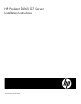
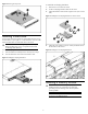
Identifying server components Front panel components Figure 1 Front Panel Components / 4 3.5” LFF HDD 2 Item Description 1 Thumbscrews for rack mounting 2 Drive status LED 3 Drive activity LED 4 Optical disc drive (optional) 5 Serial number pull tab 6 Front panel USB 2.
Figure 2 Front Panel Components / 8 2.5” SFF HDD Item Description 1 Thumbscrews for rack mounting 2 Drive status LED 3 Drive activity LED 4 Serial number pull tab 5 Optical disc drive (optional) 6 Front panel USB 2.
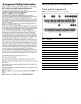
Item Description 9 4-pin power connector 10 24-pin power connector 11 Fan connector 1 12 Fan connector 2 13 DIMM slot 1 for processor 2 14 Backplane I2C connector 15 8-pin power connector 16 Fan connectors 3/4 17 Fan connector 5 18 Internal USB 2.0 port 19 SD card USB 2.0 port 20 Front panel USB 2.
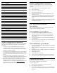
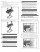
Figure 5 Removing the Top Cover To install the non-hot-plug hard drive: 1. Remove the 5 screws from the carrier. 2. Put the non-hot-plug hard drive disk into the carrier. 3. Fasten the hard drive to the carrier using the screws (two on each side). Figure 7 Installing the Non-hot-plug Hard Drive into the Carrier Installing a hard drive The drive bays on the front panel can accommodate up to four 3.5 in. LFF hard drives or up to eight 2.5 in. SFF hard drives.
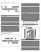
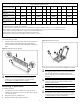
Memory Module Population Order Processor memory socket Rank support per memory socket RDIMM Population order without QR UDIMM Population order without QR Population order with QR along with SR/DR Processor memory bank number 1 2 3 4 5 6 7 8 9 10 11 12 SR/DR SR/DR/QR SR/DR SR/DR SR/DR/QR SR/DR SR/DR SR/DR/QR SR/DR SR/DR SR/DR/QR SR/DR A I E C K G B J F D L H E C G B F D A H E A I G C K F B J H D L 1 3 2 1 3 2 1 3 2 1 3 2 NOTES: SR = Single
To install the heat sink: 1. Properly align the heat sink spring-loaded screws to the system board mounting holes. 2. Tighten the spring-loaded screws clockwise to secure the heat sink connection to the system board. IMPORTANT: If the heat sink has been removed for any reason, it is critical that you apply more thermal interface material to the integrated heat spreader on the processor to ensure proper thermal bonding between the processor and the heat sink.
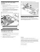
Installing the SD card reader module Figure 16 Installing the Dedicated Management Port Card To install the SD card reader module: 1. Remove the SD card reader module knock-out from the back panel of the server. 2. Align the SD card reader module to the back panel, and tighten the screw that secures the module to the chassis. 3. Connect the USB cable to the SD card reader module USB connector and link the other side of the USB cable connector to the system board.