HP ProLiant DL180 Generation 5 Server Software Configuration Guide Part number: 458197-001 First edition: January 2008
Legal notices © Copyright 2008 Hewlett-Packard Development Company, L.P. The information contained herein is subject to change without notice. The only warranties for HP products and services are set forth in the express warranty statements accompanying such products and services. Nothing herein should be construed as constituting an additional warranty. HP shall not be liable for technical or editorial errors or omissions contained herein. Microsoft, Windows, and Windows NT are U.S.
Contents System BIOS configuration System BIOS overview ............................................................................................................................ 5 AMIBIOS software ................................................................................................................................. 5 AMIBIOS Setup Utility............................................................................................................................. 5 Accessing the Setup Utility....
Contents Red Hat Enterprise Linux 4 and 5 installation ...................................................................................... 34 Section 1. Launching the Red Hat Enterprise Linux installer .............................................................. 34 Section 2. Customizing the installation.......................................................................................... 34 Section 3. Installing Red Hat Enterprise Linux 4 and 5 .....................................................
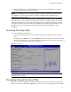
System BIOS configuration System BIOS configuration This chapter describes the basic functions of the AMIBIOS software. System BIOS overview A Basic Input/Output System, or BIOS, is a set of programs permanently stored in an EEPROM chipset located on the system board. These programs serve as an interface between the server’s hardware components and its operating system.
System BIOS configuration • When a configuration error is detected by the system and you are prompted by a "Run Setup" message to make changes to the BIOS settings. NOTE: If you repeatedly receive “Run Setup” messages, the battery located on the system board may be defective. In this case, the system cannot retain configuration values in CMOS. Ask a qualified technician for assistance. The Setup Utility loads the configuration values in a battery-backed nonvolatile memory called CMOS RAM.
System BIOS configuration of the Main menu. Table 1 Setup Utility navigation keys lists these legend keys and their respective functions. Table 1 Setup Utility navigation keys Key Function ← and → Move between selections on the menu bar. ↑ and ↓ Move the cursor to the field you want. The currently selected field is highlighted. The right side of each menu screen displays the Item Specific Help panel. This panel displays the help text for the selected field.
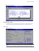
System BIOS configuration Figure 2 General Help Screen Setup Utility menus The Setup Utility menu bar displays the five primary menu selections. For detailed information and screenshots of these Setup menus and their related submenus, refer to the following sections. Main Menu Figure 3 Main Menu NOTE: The time is in 24-hour format. For example, 5:30 A.M. appears as 05:30:00, and 5:30 P.M. as 17:30:00. If you clear CMOS, setup time and date values will be BIOS release date.
System BIOS configuration Table 2 Main menu fields Field Description System Overview Displays the system ROM version, the date when the Setup utility was created and identification number. Processor Displays the CPU type, speed and count. System Memory Displays the amount of conventional memory detected. Asset Tag Enter the server asset tag. System Serial Number Enter the server serial number. The serial number is indicated on the serial number label pull tab on the front panel.
System BIOS configuration Table 3 Boot Features fields Field Description Resume On LAN Set this value to allow system wake up on LAN from Hibernation. Bootup NumLock Restore on AC Power Loss Options Enabled Cannot wake up the system from Hibernation if set to Disabled Disabled Set this value to allow Num Lock on the keyboard to be enabled automatically when the computer system boots up. This allows the immediate use of the numeric keypad located on the right side of the keyboard.
System BIOS configuration NOTE: The CPU Configuration setup screen varies depending on the installed processor. Table 4 Advanced menu fields Field Description CPU Configuration Use this screen to select options for the CPU Configuration Settings. Harddisk Configuration Use this screen to select options for the Harddisk Configuration Settings. I/O Device Configuration Use this screen to select options for the I/O device configuration settings. Use the up and down keys to select an item.
System BIOS configuration Table 5 CPU Configuration submenu fields Field Description Options Core Multi-processing Set this value to support multi-core processor. The optimal and setup default setting is Enabled. Enabled This setting configures single logical option processor mode; Only core 0, Disabled logical processor 0 remains active. Intel(R) SpeedStep (tm Tech) This setting is available if the processor supports SpeedStep.
System BIOS configuration Table 6 Harddisk Configuration submenu fields Field Description Options Set this value to prevent the hard disk drive from being erased. Enabled I/O Device Configuration submenu Figure 8 I/O Device Configuration submenu Table 7 I/O Device Configuration submenu fields Option Description Disabled Set this value to prevent the serial port from accessing any system resources.
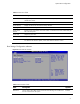
System BIOS configuration IPMI Configuration submenu Figure 9 IPMI Configuration submenu Table 8 IPMI Device Configuration submenu fields Field Description System Event Logging Select to enable/disable IPMI event logging. Disabling will still log events received via the system interface. Event Log Control Select to control event log configuration, from this configuration screen. BIOS Post Watchdog Select to enable POST watchdog. OS Boot Watchdog Select to enable OS boot watchdog.
System BIOS configuration Table 8 IPMI Device Configuration submenu fields Field Description Serial Port Assignment Select to assign the serial port connector to the system or to the BMC (Baseboard Management Controller) Serial Port Switching Enabling received escape sequences to switch serial port connector assignment. DCD Snooping Select to enable/disable mux switch to BMC on DVD loss. Serial Port Connection Model Select modem connect mode or direct connect mode.
System BIOS configuration Table 10 Console Redirection submenu fields Field Description Options Console Redirection Setting this value will enable console redirection. Enabled Setting this value will disable console redirection and prevent configuration of serial port.
System BIOS configuration Table 11 USB Configuration submenu fields Field Description Options USB Controller This setting enables the onboard USB controller. This is the default setting. Enabled This setting disables the onboard USB controller. Disabled USB 2.0 Controller This setting allows the use of USB ports at a data transfer rate of 480 Mbps. Mode This setting allows the use of USB ports at a data transfer rate of 12 Mbps. Full Speed Hi Speed This is the default setting.
System BIOS configuration Boot Menu Figure 13 Boot Menu Table 12 Boot Menu fields Field Description 1st Boot Device Set the device as the first boot device. (e.g. system boot from CD-ROM) 2nd Boot Device Set the device as the seconde boot device 3rd Boot Device Set the device as the third boot device. Removable Drives Enter this submenu is to view and configure removable drives in the system. Embedded NIC Port PXE Use this screen to configure the embedded NIC Port PXE boot option.
System BIOS configuration This panel indicates whether or not an Administrator Password has been configured. To set an administrator password: 1. In the Security menu screen, in the Change Admin Password field, press Enter. The Enter New Password window displays. Figure 15 Enter New Password 2. Type a new password in the Enter New Password box. The password may consist of up to six alphanumeric characters (A-Z, a-z, 0-9), Next, press Enter, and the Confirm New Password window displays.
System BIOS configuration Figure 16 Confirm New Password 3. Retype the new password in the Confirm New Password box to verify the first entry, and then press Enter. The Password Installed OK windows display. Press OK to continue. 4. Press F10 to save the password and close the Setup Utility. To change the Power-on password: 1. In the Security menu screen, in the Change Power-on Password field, press Enter. The Enter New Password window displays. Type a new password in the Enter New Password box. 2.
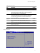
System BIOS configuration Exit menu The Exit menu displays several options for how to quit the Setup Utility. Select any of the exit options and press Enter. Figure 18 Exit menu Table 13 Exit menu fields Option Description Save Changes and Exit Save the changes made and exit the Setup Utility Discard Changes and Exit Discard the changes and exit the Setup utility Discard Changes Discard any changes made thus far in the Setup utility.
System BIOS configuration 1. Reboot the server in a normal manner. 2. During POST, press F10 to access the Setup Utility. 3. Press F9 to load the default values. 4. Press F10 to save the changes and close the Setup Utility. Clearing CMOS You may need to clear the Setup configuration values (CMOS) if the configuration has been corrupted, or if incorrect settings made in the Setup Utility have caused error messages to be unreadable. Clearing the CMOS data removes the administrator password.
System BIOS configuration Recoverable POST Errors Whenever a non-fatal error occurs during POST, an error message describing the problem appears onscreen. These text messages are displayed in normal video (white text on black background). It shows the details of the error.
System BIOS configuration 8. Repeat steps 4 and 5. If the server now works, replace the boards and accessories one at a time to determine which one is causing the problem. Reprogramming the BIOS with the crisis recovery jumper If the BIOS become corrupted, use the crisis recovery jumper to reprogram the BIOS. You will also need a USB floppy drive and the HP crisis recovery floppy disk. The crisis recovery jumper is on jumper block P56 on the system board.
NOS installation NOS installation Supported NOS Table 14 Supported network operating systems (NOS) NOS Version On-line information site Microsoft Windows Microsoft Windows Server 2003 SP2—Enterprise, Standard, and Web Editions Microsoft Windows Server 2003 R2 SP2—Enterprise, Standard, and Web Editions Microsoft Windows Server 2003 SP2 for 32bit and 64-bit Microsoft World Wide Web access: http://www.microsoft.com Microsoft Product Support Services: http://support.microsoft.
NOS installation • If you want to recycle used hard drives, use a utility such as fdisk to erase all data and partitions from that particular hard drive. BIOS update HP recommends that you update the server BIOS with the latest system BIOS version to take advantage of the most recent compatibility fixes. You can download the latest HP ProLiant DL180 Generation 5 server BIOS at www.hp.com.
NOS installation 2. Insert the Support CD into the optical media drive. By default, the Support CD automatically runs and displays the Welcome page. However, if this does not occur, double-click the Startup.htm file located on the root directory of the Support CD. 3. Follow the on-screen instructions to create the Windows NOS driver diskette. 4. Label, date, and save the driver diskette as HP disk [Windows NOS version]. Section 2. Installing Windows NOS 1. Boot the server from the Windows NOS CD-ROM.
NOS installation If you have successfully installed the Windows NOS, the Configure Your Server wizard launches. Close this window to postpone the customization of the server until all of the installation steps are completed. You can open the Configure Your Server wizard at any point by clicking Start | Programs |Administrative Tools | Configure Your Server. Section 3. Completing the installation Phase 1 - Installing the chipset driver 1. Insert the Support CD in the server’s optical media drive.
NOS installation Phase 3 - Installing the embedded video driver 1. Insert the Support CD in the server’s optical media drive. By default, the Support CD automatically runs and displays the Welcome page. However, if this does not occur, double-click the Startup.htm file located on the root directory of the Support CD. 2. Click the HP ProLiant DL180 Generation 5 server drivers for chipset, Network, and Video link. 3. Select the embedded VGA driver for the Windows [NOS version] option.
NOS installation Phase 2 - Initializing the hard drive There are two types of hard drive configurations: Dynamic and Basic. You can select the appropriate type by right-clicking on the disk drive icon. • • Dynamic drives are used to create volumes, which can contain more than one physical hard drive. Basic drives are used to create primary or local partitioned drives. To manage different drives and partitions: 1. Click Start | Programs | Administrative Tools | Computer Management. 2.
NOS installation 4. Check the number of disks required and label them as Terminal Services for […] Disk [x/y]. 5. Click OK to proceed. 6. Follow the on-screen instructions to create the diskette copies. 7. Click OK at the [y] floppies were created… screen. 8. Click Cancel to close the Create Installation Disks utility. Section 5. Configuring the network Phase 1 - Configuring the server’s IP address During the installation process, the system was configured to use DHCP.
NOS installation 6. Copy files back and forth from the clients to the server. To test the network link using Terminal Services: 1. Click Start | Programs | Terminal Services Client | Terminal Services Client on a client you installed Terminal Services on. 2. Select the target server from the Available Servers list displayed on the screen. 3. Click Connect. 4. Complete the User ID and Password login form.
NOS installation 19. If prompted, insert the Windows NOS CD-ROM, and then click OK to continue. The Configuring active directory display shows again. 20. Click Finish to close the Wizard utility. This completes the active directory installation. 21. Click Restart Now to reboot the system. Remove the Windows NOS CD-ROM if it is present. 22. At the login prompt: a. Type in the administrator password you set. b. Click Options and verify that the Log on to: HOST displays on the dialog box. c.
NOS installation − Browser that supports HTML ○ Two or more clients for testing purposes (optional) Red Hat Enterprise Linux 4 and 5 installation The procedures in this section apply to all versions of the Red Hat Enterprise Linux 4 and 5 supported by your ProLiant server. Refer to Table 14 on page 25 for a list of these NOS versions. NOTE: If the system has more than 4 GB of memory, the Red Hat Enterprise Linux installation requires the pci=nommconf parameter. Section 1.
NOS installation Review the Additional Language Support setting and modify if necessary, then click Next to continue. Time Zone Selection Review the Time Zone Selection setting and modify if necessary, then click Next to continue. Set Root Password Enter a root password consisting of at least six alphanumeric characters, then click Next to continue. Package Defaults Review the software selection and modify if necessary, then click Next to continue.
NOS installation Retain the default display setting, then click Next to continue. System User 1. Skip the option to create a new user, then click Next to continue. 2. On the Warning dialog box, click Next to continue. Additional CDs Ignore this page. Click Next to continue. Finish Setup The initial setup configuration is complete. Click Next to proceed to the login window. Login Type root and the password you set during the NOS installation, then press Enter.
NOS installation SUSE Linux Enterprise Server 9 installation Section 1. Installing SUSE Linux Enterprise Server 9 1. Turn on the server and insert the SUSE Linux Enterprise Server 9 SP3 (SLES9) CD 1. 2. Reboot the system to the SLES9 SP3 CD 1. 3. Select Installation, then press Enter to start the installation. 4. Remove the SLES9 SP3 CD1 and insert the SLES9 CD 2 once prompted. 5. Press Enter to proceed to the customization of your installation. Section 2.
NOS installation Select the authentication method appropriate for your environment, then click Next to continue. Add a New Local User Follow the prompt to add a new local user account, then click Next to continue. Release Note Review the release notes, then click Next to continue. Hardware Configuration Review the default hardware settings and modify them as necessary, then click Next to continue. Installation Completed Click Finish to proceed to the login window.
NOS installation Section 3. Completing the installation Hostname and Domain Name Set host name and domain name, then click Next to continue. Password for the System Administrator Enter a root password consisting of at least six alphanumeric characters, then click Next to continue. Network Configuration Review the Network Configuration settings and verify that they fit your environment, then click Next to continue.
NOS installation − Floppy drive − Optical media drive − Browser that supports HTML ○ Two or more clients for testing purposes (optional) Installation flow 1. Install Sun Solaris 10. Refer to the next section for detailed instructions. 2. Install additional HP accessories. The HP ProLiant DL180 Generation 5 Server Support CD includes the drivers for accessories compatible to your server.
NOS installation HP recommends the 1024 x 768 – 65536 colors option. 8. Select Save and Test the Window System Configuration, then press F2. 9. Press F2 again to test the hardware configuration settings you selected. If you are able to view the sample display, click Yes to return to the GUI installation mode. If the hardware test fails, repeat steps 1-9 until the correct settings are made. Select Language Select the language you prefer for the installation, then press Enter to continue.
NOS installation Click Custom Install, then click Next to choose the Solaris options you intend to install. Select Software Localizations Click a > on the GUI to expand a geographic region option, then select the appropriate localization(s). Click Next to continue. Select System Locale Select the appropriate locale once the installation is complete, then click Next to continue. Select Products Select the Solaris software products you need, then click Next to continue.
Server management Pre- and post-installation procedures Pre-installation procedures WARNING: Failure to properly turn off the server before you open the server or before you start removing or installing hardware components may cause serious damage as well as bodily harm. WARNING: To reduce the risk of personal injury from hot surfaces, allow the chassis and any installed hardware components to cool before touching them.
Server management laptop) that is connected to the serial port on the server. The serial port can be controlled by the server or shared between the server and the BMC (the default setting). To configure the BMC through the Setup Utility: 1. In the IPMI submenu, set the Serial port Assignment field to System or BMC. 2. In the LAN Settings field under the IPMI submenu, set the IP address, default gateway, and IP subnet mask for the BMC.
Server management 14. Browse the server settings using the user interface that displays. To enable console redirection via the Setup Utility: 1. In the serial port assignment, set the Serial port Mode field to BMC. 2. In the Console Redirection submenu, set BIOS Serial console and EMS Support(SPCR) as Enable. 3. Press F10 to Save and Exit Console Redirection submenu fields.
Index Index A E Pre-installation, 39 administrator password, 18 administrator password changing, 20 AMIBIOS Setup Utility, 5 asset tag, 9 Embedded NIC PXE, 18 Exit menu, 21 R B Basic Input/Output System, 5 BIOS overview, 5 Boot Device Priority, 18 Boot Settings Configuration, 9 Bootup Num-Lock, 10 G General Help Screen, 8 I IDE, 13 IP subnet mask, 44 IPMI LAN interface, 44 RAID, 13 Red Hat Enterprise Linux 3, 35 Remote Access, 16 Restore on AC Power Loss, 10 ROM version, 9 S Clear BMC System Eve