HP ProLiant DL180 Server Software Configuration Guide Part number: 451525-001 First edition: June 2007
Legal notices © Copyright 2007 Hewlett-Packard Development Company, L.P. The information contained herein is subject to change without notice. The only warranties for HP products and services are set forth in the express warranty statements accompanying such products and services. Nothing herein should be construed as constituting an additional warranty. HP shall not be liable for technical or editorial errors or omissions contained herein. Microsoft, Windows, and Windows NT are U.S.
Contents System BIOS configuration ...................................................................................................................... 5 System BIOS overview .............................................................................................................................. 5 AMIBIOS software ................................................................................................................................... 5 AMIBIOS Setup Utility.................................
Post-installation procedures................................................................................................................. 72 Configuring the BMC ............................................................................................................................. 72 Index ..................................................................................................................................................
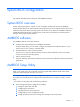
System BIOS configuration This chapter describes the basic functions of the AMIBIOS software. System BIOS overview A Basic Input/Output System, or BIOS, is a set of programs permanently stored in an EEPROM chipset (U70) located on the system board. These programs serve as an interface between the server’s hardware components and its operating system.
• When a configuration error is detected by the system and you are prompted by a Run Setup message to make changes to the BIOS settings. NOTE: If you repeatedly receive “Run Setup” messages, the battery located on the system board (XBAT1) may be defective. In this case, the system cannot retain configuration values in CMOS. Ask a qualified technician for assistance. The Setup Utility loads the configuration values in a battery-backed nonvolatile memory called CMOS RAM.
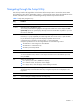
Navigating through the Setup Utility Use the keys listed in the legend bar on the bottom of the Setup screen to access the various menu and submenu screens of the Setup Utility. Figure 1 in the previous section shows the legend bar at the bottom of the Main menu. Table 1 lists these legend keys and their respective functions. Table 1 Setup Utility navigation keys Key Function ← and → Move between selections on the menu bar. ↑ and ↓ Move the cursor to the field you want.
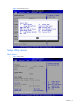
Figure 2 General Help Screen Setup Utility menus Main Menu Figure 3 Main Menu Contents 8
NOTE: The time is in 24-hour format. For example, 5:30 A.M. appears as 05:30:00, and 5:30, P.M. as 17:30:00. If you clear CMOS, setup time and date values will be 00:00:00 and 02/29/2006. Table 2 Main menu fields Field Description System Overview Displays the system ROM Version, the date when the Setup utility was created and identification number. Processor Displays the CPU version, speed and count. System Memory Displays the amount of conventional memory detected during POST.
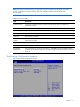
Table 3 Boot Settings Configuration submenu fields Field Description Options Summary Screen Set this value to not allow display hardware summary screen before booting the OS. Boot up NumLock Set this value to allow display s hardware summary screen before booting the OS Enabled Set this value to allow the Number Lock on the keyboard to be enabled automatically when the computer system is boot up. This allows the immediate use of 10-keys numeric keypad located on the right side of the keyboard.
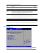
Table 4 Advanced Settings Field Description CPU Configuration Use this screen to select options for the CPU Configuration Settings. Use the up and down keys to select an item. Use the and keys to change the value of the selected option. A description of the selected item appears on the right side of the screen. The settings are described on the following pages. IDE Configuration Use this screen to select options for the IDE Configuration Settings.
CPU Configuration submenu Figure 6 CPU Configuration submenu Table 5 CPU Configuration submenu fields Field Description Options Adjacent Cache Line Prefetch This should be enabled in order to enabled or disable the Adjacent Cache Line Prefetch Disabled Feature. This is the default setting. Enabled Disabled the item. Not support adjacent cache line Prefetch debug function. Disabled Set this value only core0.logical processor 0 remains active.
IDE Configuration submenu Figure 7 IDE Configuration submenu Table 6 IDE Configuration submenu fields Field Description Options ATA/IDE Configuration Set this value to prevent the computer system from using the integrated IDE and SATA controller. Disabled Set this mode to support compatible mode. Compatible Set this mode to support enhanced mode. This is the default value.
Figure 8 IDE Configuration submenu ---- Enhanced Table 7 Configure SATA as submenu fields Option Description IDE Setting this value configures SATA in IDE mode. This is default value. RAID Setting this value configures SATA in RAID mode. AHCI Setting this value configures SATA in AHCI mode.
Figure 9 IDE Configuration submenu -- Compatible NOTE: When setting Compatible mode, you can configure Legacy IDE Channels. Table 8 Configure SATA as submenu fields Option Description SATA Only Set this value to only support SATA Device. PATA Pri,SATA Sec Set this value to support PATA as primary device, select SATA as secondary Device. SATA Pri,PATA Sec Set this value to support SATA as primary device, select PATA as secondary Device. PATA Only Set this value to only support PATA Device.
Figure 10 IDE Configuration submenu ---- Disabled Table 9 Hard Disk Write Protect submenu fields Option Description Enabled This value enables hard disk write protection. This setting is only effective if device is accessed through BIOS. This is the default setting. Disabled This value disables hard disk write protection. This setting is only effective if device is accessed through BIOS.
IO Device Configuration submenu Figure 11 IO Device Configuration submenu Table 10 IO Device Configuration submenu fields Field Description Options Serial Prot1 Address Set this value to prevent the serial port from accessing any system resources. Disabled When this option is set to Disabled, the serial port physically becomes unavailable Set this value to allow the serial port to use 3F8 as its I/O port address and IRQ 4 for the interrupt address. This is the default setting.
Event Log Configuration submenu Figure 12 Event Log Configuration submenu Table 11 Event Log Configuration submenu fields Field Description Options View Event Log This option displays the event log. The log displays system event information. Mark all events The option marks all events as read. as read Clear Event Log The option allows the user to clear the event log. ECC Event Logging This setting allows logging of ECC events.
AHCI Configuration submenu Figure 13 AHCI Configuration submenu NOTE: While entering AHCI Port setup, BIOS auto detects the presence of devices. This displays the status of auto detection of SATA Port devices, there are two statuses, hard disk and not detected.
IPMI Configuration submenu Figure 14 IPMI Configuration submenu Table 12 IPMI Device Configuration submenu fields Field Description SEL Configuration Select SEL configuration in the left frame of the screen to go to the sub menu for that item. Then you can press Enter to enter its sub-menu. You can display an about SEL Configuration option by highlighting it using the keys.
Figure 15 SEL Configuration submenu Table 13 SEL Configuration submenu fields Field Description View BMC System Event Log The option specifies BMC system event log. Select this option and press to access the sub menu you can view the contents of System Event log. Clear BMC System Event Log The option specifies clear system event log. If the BMC Event log is full, you can choose this item to clear out the BMC Event log.
Figure 16 View BMC System Event Log submenu Figure 17 Serial Port Configuration Contents 22
Table 14 Serial Port Configuration submenu fields Field Description Options Serial Port Assignment This setting will assign the serial port connector to the system. This is the default setting. System This setting will assign the serial port connector to the BMC (Baseboard management controller BMC Serial Port Switching This setting allows the Serial port switch between system and BMC.
Table 15 LAN Configuration submenu fields Field Description Options Setting this value will allow manual IP assignment. Disabled Figure 19 Watchdog Configuration submenu Table 16 Watchdog Configuration submenu fields Field Description Options POST Watchdog Timer Action Set this value to allow BMC to reset if the operating system crashes or hangs. Reset System Disabling this option disables any BMC action if OS crashes or hangs. This is the default setting.
Table 16 Watchdog Configuration submenu fields Field Description Options Sets a 15 minute timeout valuefor BMC to wait before assuming the system has crashed and needs to reset. 15 Min Sets a 20 minute timeout value for BMC to wait before assuming the system has crashed and needs to reset. 20 Min Sets a 25 minute timeout valuefor BMC to wait before assuming the system has crashed and needs to reset.
Figure 21 Fan Control Policy submenu Remote Access Configuration submenu Figure 22 Remote Access Configuration submenu Contents 26
Table 17 Remote Access Configuration submenu fields Field Description Options Remote Access Configure remote access type and parameters Disabled EMS support(SPCR) Setting this value to prevent the BIOS from using EMS Support (SPCR) function Disabled Setting this value to support the BIOS from using EMS Support (SPCR) Enabled USB Configuration submenu Figure 23 USB Configuration submenu Table 18 USB Configuration submenu fields Field Description Options USB Controller This setting allows the
Table 18 USB Configuration submenu fields Field Description Options BIOS EHCI HandOff Set this value can support the EHCI-off, this is default value. Enabled Set this value not allow support the EHCI-off. Disabled Boot Menu Figure 24 Boot Menu Table 19 Boot Menu Field Description Boot Device Priority Use this screen to specify the order in which the system checks for the device to boot from.
Table 19 Boot Menu Field Description Network Drives Use this screen to network drives in the system. To access this screen, select network drives on the Boot Setup screen and press . Then you can select It as the first boot device or disabled it as the 1st Drive. Embedded NIC PXE The option specifies the embedded NIC PXE.
Figure 26 Hard Disk Drives submenu Table 20 Hard Disk Drives fields Option Description HDD Select this device as the 1st Drive. Disabled Disabled the hard disk as the first boot device.
Figure 27 Removable Drives submenu Table 21 Removable drives Option Description Removable Select this device as the 1st Drive. Disabled Disabled the removable as the first boot device.
Figure 28 CD/DVD Drives submenu Table 22 CD/DVD drives Option Description CD/DVD Select this device as the 1st Drive. Disabled Disabled the CD/DVD Drives as the first boot device.
Figure 29 Network Drives submenu Table 23 Network Drives fields Option Description Embedded NIC Select this device as the 1st Drive. Disabled Disabled the network drive as the first boot device.
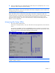
Security menu The Security menu allows users to set an administrator password. When entered, this password allows the user to access and change all settings in the Setup Utility. Figure 30 Security menu To set an administrator password: 1. Indicates whether a supervisor password has been set, If the password has been installed, Installed displays, if not, not installed displays. In the Security menu screen, in the Change Administrator Password field, press Enter. The Enter New Password window displays.
Figure 31 Enter New Password 2. Type a new password in the Enter New Password box. The password may consist of up to eight alphanumeric characters (A-Z, a-z, 0-9), then press Enter , The Confirm New Password window displays. Figure 32 Confirm new password 3. Type the same password in the Confirm New Password box to verify the first entry, then press Enter. The Password Installed OK windows displays, press OK finish the password installed.
Figure 33 Password installed 4. Press F10 to save the password and close the Setup Utility. Setup automatically changes the administrator Password Is field to set. To change the administrator password: 1. In the Security menu screen, in the Change Administrator Password field, press Enter. The Enter New Password window displays. Type a new password in the Enter New Password box.
2.
1. In the Security menu screen, in the Clear Administrator Password field, press Enter. The Clear Administrator Password window displays. The OK is to clear the administrator password, the cancel is to discard the password. Figure 37 Clear Administrator Password submenu 2. In the Security menu screen, in Password Check [setup] field, press Enter. The Setup is to check password while invoking setup, the Always is to check password while invoking setup a well as on each boot.
Table 24 Password Check fields Option Description Setup Set this value need to check password while invoking the set up utility. Always Set this value must check password while invoking setup on each boot. 3. Press F10 to save the changes you made and close the Setup Utility. Exit menu The Exit menu displays several options on how to quit the Setup Utility. Select any of the exit options then press Enter.
• • • BIOS version and release date • • • • Serial port base I/O address BMC firmware version Size of the system and video memory, as well as the memory size allotted for the cache RAM and option ROM Available hard drives and expansion boards Server asset tag and serial number MAC address of each of the three LAN ports It is recommended that you check this screen during the initial system setup and each time you install, remove, or upgrade accessories.
Recording custom Setup values Write down the settings from the Setup Utility and keep them in a safe place. If the custom values ever need restoring (after clearing CMOS, for example), you must run the Setup Utility and enter these custom settings again. Having a record of these custom settings makes this much easier. Loading system defaults If the system fails after you make changes in the Setup menus, reboot the server, enter Setup, and load the system default settings to correct the error.
These diagnostics, which reside in the BIOS ROM, isolate server-related logic failures and indicate the board or component that needs to be replaced, as indicated by the error messages. Most server hardware failures are accurately isolated during POST. The number of tests displayed depends on the configuration of the server.
Table 26 POST Error Messages Error code Error message Description/corrective action 0250 System battery is dead Replace and run SETUP The CMOS clock battery indicator shows the system battery is dead. 1 Replace the system battery following the procedures in the HP ProLiant 2 0251 System CMOS checksum bad - Default configuration used DL180 Server Maintenance and Service Guide. Run Setup to reconfigure the system.
If an optional POST code expansion board is installed in the server, during these instances, the server emits a buzzing sound followed by a series of audible beeps. An external ROM module can also issue audible errors, usually consisting of one long tone followed by a series of short tones. If you get a blank screen on boot but hear beeps, count the beeps and refer to Table 18 for their corresponding meaning. If you miss the beep code: 1.
Table 27 Checkpoint codes 16h BIOS ROM checksum 17h Initialize cache before memory auto size 18h 8254 timer initialization 1Ah 8237 DMA controller initialization 1Ch Reset programmable interrupt controller 20h 1-3-1-1 Test DRAM refresh 22h 1-3-1-3 Test 8742 keyboard controller 24h Set ES segment register to 4 GB 26h Enable gate A20 line 28h Autosize DRAM 29h Initialize POST memory manager 2Ah Clear 512 KB base RAM 2Bh Initialize extended CMOS 2Ch 1-3-4-1 RAM failure on address
Table 27 Checkpoint codes 48h Check video configuration against CMOS 49h Initialize PCI bus and devices 4Ah Initialize all video adapters in system 4Bh Quiet boot start (optional) 4Ch Shadow video BIOS ROM 4Eh Display BIOS copyright notice 4Fh Initialize multi-boot 50h Display processor type and speed 51h Initialize EISA board 52h Test keyboard 54h Set key click if enabled 55h Enable USB devices 56h Enable keyboard 57h Enable FireWire devices 58h 2-2-3-1 Test for unexpected in
Table 27 Checkpoint codes 74h Test real-time clock 76h Check for keyboard errors 7Ah Check for key lock errors 7Ch Set up hardware interrupt vectors 7Dh Initialize Intelligent System Monitoring 7Eh Initialize coprocessor if present 80h Disable onboard super I/O ports and IRQs 81h Late POST device initialization 82h Detect and install external RS232 ports 83h Configure non-MCD IDE controllers 84h Detect and install external parallel ports 85h Initialize PCI devices 86h Re-initialize
Table 27 Checkpoint codes 9Ch Set up power management 9Dh Initialize security engine (optional) 9Eh Enable hardware interrupts 9Fh Determine number of SATA or SAS drives A0h Set time of day A2h Check key lock A4h Initialize typematic rate A8h Erase F10 prompt AAh Scan for F10 key stroke ACh Enter Setup AEh Clear boot flag B0h Check for errors B1h Inform ROM pilot about the end of POST B2h POST done, prepare to boot operating system B3h Store extended CMOS B4h 1 One short bee
Table 27 Checkpoint codes C6h Initialize note dock (optional) C7h Initialize note dock late C8h Force check (optional) C9h Extended checksum (optional) CAh Redirect Int 15h to enable remote keyboard CBh Redirect Int 13h to memory technologies devices such as ROM, RAM, PCMCIA, and serial disk CCh Redirect Int 10h to enable remote serial video CDh Re-map I/O and memory for PCMCIA CEh Initialize digitizer and display message POST-related troubleshooting Perform the following procedures when
7. Remove all accessories, except the primary boot hard disk drive. 8. Repeat steps 4 and 5. If the server now works, replace the boards and accessories one at a time to determine which one is causing the problem. Reprogramming the BIOS with the crisis recovery jumper If the BIOS becomes corrupted, use the crisis recovery jumper to reprogram the BIOS. You will also need a USB floppy drive and the HP crisis recovery floppy disk. The crisis recovery jumper is on jumper block P56 on the system board.
NOS installation Supported NOS Table 28 Supported network operating systems (NOS) NOS Version On-line information site Microsoft Windows Microsoft Windows Server 2003—Enterprise, Standard, and Web Editions Microsoft Windows Server 2003 R2—Enterprise, Standard, and Web Editions Microsoft Windows Server 2003 for 64-bit Microsoft World Wide Web access: www.microsoft.com Microsoft Product Support Services: http://support.microsoft.
recommends that you install and configure any of these hard drives after completing the NOS installation. • If you want to recycle used hard drives, use a utility such as fdisk to erase all data and partitions from that particular hard drive. BIOS update HP recommends that you update the server BIOS with the latest system BIOS version to take advantage of the most recent compatibility fixes. You can download the latest HP ProLiant DL180 server BIOS at www.hp.com.
2. Insert the Support CD into the optical media drive. By default, the Support CD automatically runs and displays the Welcome page. However, if this does not occur, double-click the Startup.htm file located on the root directory of the Support CD. 2. Follow the on-screen instructions to create the Windows NOS driver diskette. 2. Label, date, and save the driver diskette as HP disk [Windows NOS version]. Section 2. Installing Windows NOS 1. Boot the server from the Windows NOS CD-ROM.
If you have successfully installed the Windows NOS, the Configure Your Server wizard launches. Close this window to postpone the customization of the server until all of the installation steps are completed. You can open the Configure Your Server wizard at any point by clicking Start > Programs > Administrative Tools > Configure Your Server. Section 3. Completing the installation Phase 1 - Installing the chipset driver 1. Insert the Support CD in the server’s optical media drive.
Select the embedded VGA driver for the Windows [NOS version] option. The File Download dialog box displays. 3. Click Open to download the driver. The Security Warning dialog box displays. 4. Click Yes. The installation menu for the selected driver is displayed. 5. Follow the on-screen instructions to install the embedded VGA driver. 6. After completing the installation, reboot the server. Section 4.
To manage different drives and partitions: 1. Click Start | Programs | Administrative Tools | Computer Management. 2. Double-click Storage in the tree, then click Disk Management. The Write Signature and Upgrade wizard starts if you have new hard drives with no signatures on them. 3. Follow the on-screen instructions to create the signature. 4. Select the available hard disk space on the graphic and use menus to create additional partitions. 5. Format all partitions that are not yet formatted. 6.
Section 5. Configuring the network Phase 1 - Configuring the server’s IP address During the installation process, the system was configured to use DHCP. If no DHCP server is found on the network, the system autoconfigures a random IP address to start functioning. It is important that you configure the proper IP address to be able to communicate with the clients. 1. Right-click My Network Places | Properties, then double-click Local Area Connection on your server.
Phase 3 - Configuring the domain controller setup The Windows NOS manual calls this process "Promoting the server to a domain controller.” 1. Click Start | Programs | Administrative Tools | Configure Your Server. 2. Select Active Directory. 3. Scroll down and click Start the Active Directory wizard. 4. Click Next to continue. NOTE: The following instructions correspond to the standard steps for new domain creation. You may customize the options proposed by your Windows NOS to match your environment.
Section 6. Installing additional HP accessories The HP ProLiant DL180 Server Support CD includes the drivers for accessories compatible to your server. Refer to the product manual enclosed with the accessory for the detailed installation procedure and/or to the attached readme.txt file associated with the driver. The readme.txt file can be found on the appropriate driver diskette. Installing Red Hat Enterprise Linux NOS Installation flow 1. Install Red Hat Enterprise Linux [version].
2. Press Enter to start the installation. 3. At the CD Found dialog box, click Skip. The Welcome to Red Hat Enterprise Linux page displays. 4. Click OK to proceed to the customization of your installation. Section 2. Customizing the installation Language Selection Select the language you prefer for the installation, then click OK to continue. Keyboard Selection Your HP server comes with a Generic 104-key PC keyboard.
Time Zone Selection Review the Time Zone Selection setting and modify if necessary, then click OK to continue. Root Password Enter a root password consisting of at least six alphanumeric characters, then click OK to continue. Package Defaults 6. Review the software selection and modify it as necessary, then click OK to continue. Package Group Selection 7. Review and modify the selection as necessary, then click OK to continue.
2. Press Enter to start the installation. 3. At the CD Found dialog box, click Skip. The Welcome to Red Hat Enterprise Linux page displays. 4. Click Next to proceed through the customization of your installation. Section 2. Customizing the installation Language Selection Select the language you prefer for the installation, then click Next to continue. Keyboard Configuration Your HP server comes with a Generic 104-key PC keyboard.
NOTE: Remember to select the appropriate package groups that match your network settings. For example, the DNS Name Server package may be required if you have set-up your new server to be the DNS controller. Section 3. Installing Red Hat Enterprise Linux 4 About to Install Once you complete the customization, the installation program asks for confirmation before proceeding with the install. 1. Click Next to proceed with the installation. 2.
Installing SUSE Linux Enterprise Server NOS The procedures in this section apply to the SUSE Linux Enterprise Server NOS, version 9 and 10. Installation flow 1. Install SUSE Linux Enterprise [version]. For the specific procedure for each SLE NOS version, refer to the following sections. 2. Install additional HP accessories. The HP ProLiant DL180 Server Support CD includes the drivers for accessories compatible to your server.
Installation Setting 1. Click New Installation, then click OK. The installer automatically enables the default settings. 2. Review the default installation settings and modify them to meet your network environment. 3. Click Accept to initialize the installation process. 4. Click Yes, install on the warning dialog box to start the file copying. You may be prompted to insert the rest of the SLES9 CD-ROMs, depending on the installation settings you have chosen.
3. Select Installation, then press Enter to proceed to the customization of your installation. Section 2. Customizing the Installation Language Select the language you prefer for the installation, then click Accept to continue. Media Check Skip this stage of the installation. Click Next to continue. License Agreement Read the license agreement. If the terms of the agreement are acceptable, click Yes, I agree to the license agreement, then click Next to continue.
Follow the prompt to add a new local user account, then click Next to continue. Release Note Review the release notes, then click Next to continue. Hardware Configuration Review the default hardware settings and modify them as necessary, then click Next to continue. Installation Completed Click Finish to reboot the system and proceed to the login window Installing Sun Solaris 10 Perform the procedures in this section to install Sun Solaris 10 to your ProLiant server. Pre-installation instructions 1.
3. Click Solaris, then press Enter. 4. Type 1 to select the Solaris Interactive Installation option. After a few minutes, the Proposed Window System Configuration for Installation list appears. These settings are incorrect and should be modified. 5. Press Esc to modify the settings and customize the installation. Section 2. Customizing the installation The Sun Solaris10 Installer shifts to a text-based screen for customizing the hardware selection and other options.
Set the system date and time. If the default date and time settings displayed are correct, click Next. Otherwise, adjust the date and time settings, then click Next. Click Geographic Continent/Country/Region, then click Next to continue. Root Password Enter a root password. Re-enter the password in the second box, then click Next to continue. Confirm Information A configuration information summary is displayed. Verify this information, then click Confirm to proceed to the installation proper. Section 3.
An installation information summary is displayed. Verify this information, then click Install Now to start the installation process. Upon completing the installation, the system automatically reboots. You can now eject the SS10U1 DVD. Once the system reboots, the new Sun Solaris environment is loaded.
Server management Pre- and post-installation procedures Pre-installation procedures WARNING: Failure to properly turn off the server before you open the server or before you start removing or installing hardware components may cause serious damage as well as bodily harm. WARNING: To reduce the risk of personal injury from hot surfaces, allow the chassis and any installed hardware components to cool before touching them.
4. Place the top cover in a safe place for reinstallation later. Post-installation procedures 1. Be sure all components are installed according to the described step-by-step instructions. 2. Check to make sure you have not left loose tools or parts inside the server. 3. Reinstall any expansion boards, riser board assemblies, peripherals, board covers, brackets, and system cables that you have removed. 4. Reinstall the top cover: a. Place the cover on the chassis approximately 1.25 cm (0.
7. At the Login prompt, type your user name and press Enter. The default user name is admin. 8. At the Password prompt, type your password and press Enter. The default password is admin. The message CLP Session Initiated displays. 9. At the prompt, type cd map1/nic1 to navigate to the correct directory. The command line interface is SMASH-compliant. 10. Type show to display the current settings. 11. Modify the settings you want to change. NOTE: The set variables are case-sensitive.
Index A Adjacent Cache Line Prefetch, 12 administrator password, 34 AHCI Configuration submenu, 19 AMIBIOS Setup Utility, 5 Installing Sun Solaris 10, 67 Installing SUSE Linux Enterprise Server NOS, 64 IO Device Configuration, 17 IP subnet mask, 72 IPMI Configuration submenu, 20 ATA/IDE Configuration, 14 IPMI LAN interface, 72 B L BIOS overview, 5 boot device, 31 LAN Configuration submenu, 23 LAN Controller, 72 Boot Device Priority submenu, 29 Loading system defaults, 41 Boot Menu, 28 M Boot Set
SATA Only, 15 SUSE Linux Enterprise Server 10, 65 SATA Pri,PATA Sec, 15 SUSE Linux Enterprise Server 9, 64 Security menu, 34 system configuration changing, 5 Serial Port Configuration, 22 system time and date setting, 5 Serial port Mode, 72 U Server management, 71 Setup, 5 Setup Utility menus, 8 Sun Solaris 10, 67 USB Configuration submenu, 27 V view event log, 18 Supported NOS, 51 W SUSE Linux Enterprise Server, 64 Watchdog Configuration submenu, 24 Contents 75