HP ProLiant DL185 Generation 5 Server Software Configuration Guide Part number 452453-002 Second edition March 2012
Legal notices © Copyright 2007, 2012 Hewlett-Packard Development Company, L.P. The information contained herein is subject to change without notice. The only warranties for HP products and services are set forth in the express warranty statements accompanying such products and services. Nothing herein should be construed as constituting an additional warranty. HP shall not be liable for technical or editorial errors or omissions contained herein. Microsoft, Windows, and Windows NT are U.S.
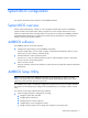
Contents System BIOS configuration .................................................................................................................... 5 System BIOS overview ................................................................................................................................. 5 AMIBIOS software ...................................................................................................................................... 5 AMIBIOS Setup Utility .............................
Configuring the BMC ................................................................................................................................ 59 Index ................................................................................................................................................
System BIOS configuration This chapter describes the basic functions of the AMIBIOS software. System BIOS overview A Basic Input/Output System, or BIOS, is a set of programs permanently stored in an EEPROM chipset located on the system board. These programs serve as an interface between the server’s hardware components and its operating system.
• When a configuration error is detected by the system and you are prompted by a "Run Setup" message to make changes to the BIOS settings. NOTE: If you repeatedly receive “Run Setup” messages, the battery located on the system board may be defective. In this case, the system cannot retain configuration values in CMOS. Ask a qualified technician for assistance. The Setup Utility loads the configuration values in a battery-backed nonvolatile memory called CMOS RAM.
Navigating through the Setup Utility Use the keys listed in the legend bar on the bottom of the Setup screen to access the various menu and submenu screens of the Setup Utility. Figure 1in the previous section shows the legend bar at the bottom of the Main menu. Table 1 Setup Utility navigation keys lists these legend keys and their respective functions. Table 1 Setup Utility navigation keys Key Function ← and → Move between selections on the menu bar. ↑ and ↓ Move the cursor to the field you want.
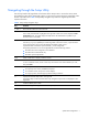
Figure 2 General Help Screen Setup Utility menus The Setup Utility menu bar displays the five primary menu selections. For detailed information and screenshots of these Setup menus and their related submenus, refer to the following sections. Main Menu Figure 3 Main Menu NOTE: The time is in 24-hour format. For example, 5:30 A.M. appears as 05:30:00, and 5:30, P.M. as 17:30:00. If you clear CMOS, setup time and date values will be 00:00:00 and 02/29/2006.
Table 2 Main menu fields Field Description System Overview Displays the system ROM Version, the date when the Setup utility was created and identification number. Processor Displays the CPU version, speed and count. System Memory Displays the amount of conventional memory detected during POST. Power Supply Displays the redundant power supply. Asset Tag Enter the server asset tag. System Serial Number Enter the server serial number.
Table 3 Boot Settings Configuration submenu fields Field Description Options Bootup NumLock Set this value to allow Num Lock on the keyboard to be enabled automatically when the computer system is booted up. This allows the immediate use of the numeric keypad located on the right side of the keyboard. To confirm this, the Num Lock LED on the keyboard ill be lit. Enabled This option does not enable the keyboard Num Lock automatically.
IDE Configuration Use this screen to select options for the IDE Configuration Settings. SuperIO Configuration Use this screen to select options for the Super I/O settings. S-ATA Configuration Use this screen to select options for the S-ATA mode settings. ACPI Configuration Use this screen to select options for the AVPI Configuration settings. Event Log Configuration Perform event log configuration, from this configuration screen. IPMI Configuration Select this option to view the contents of IPMI.
IDE Configuration submenu Figure 7 IDE Configuration submenu Table 6 IDE Configuration submenu fields Field Description Options Onboard PCI IDE Controller Set this value to allow the computer system to detect the Primary and Both Secondary IDE channels. This includes the Primary Master, Primary Slave, Secondary Master, and Secondary Slave. Set this value to allow the computer system to detect only the Primary Primary IDE channel. This includes both the Primary Master and the Primary Slave.
Table 6 IDE Configuration submenu fields Field Description Options Set this value to stop the setup from searching the IDE bus for IDE disk drives in 20 seconds 20 Set this value to stop the setup from searching the IDE bus for IDE disk drives in 25 seconds 25 Set this value to stop the setup from searching the IDE bus for IDE disk drives in 30 seconds 30 35 is the default value.
Table 7 SuperIO Configuration submenu fields Option Description 2E8/IRQ3 Set this value to allow the serial port to use 2E8 as its I/O port address and IRQ 3 for the interrupt address. If the system will not use a serial device, it is best to set this port to Disabled. 2F8/IRQ3 Set this value to allow the serial port to use 2F8 as its I/O port address and IRQ 3 for the interrupt address.
ACPI Configuration submenu Figure 10 ACPI Configuration submenu Table 9 ACPI Configuration submenu fields Field Description Options ACPI Version Features Set this value to enable ACPI Version Features Enabled Set this value to disable ACPI Version Features Disabled Set this value to enable ACPI OEMB table Enabled Set this value to disable ACPI OEMB table Disabled Set this value to disable Headless mode Disabled Set this value to enable Headless mode Enabled AMI OEMB table Headless mode S
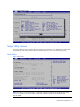
Event Log Configuration submenu Figure 11 Event Log Configuration submenu Table 10 Event Log Configuration submenu fields Field Description View Event log Display the event log contents. Mark all events as read The option allows you to mark all events as read. Clean Event log The option allows you to clean the event log.
IPMI Configuration submenu Figure 12 IPMI Configuration submenu Table 11 IPMI Device Configuration submenu fields Field Description SEL Configuration Configuration of the BMC Sensor Event Log. Serial Port Configuration Select to configure system serial ports. LAN Configuration Select for LAN configuration (when you have a LO100 Device, this item will display).
Figure 13 SEL Configuration submenu Table 12 SEL Configuration submenu fields Field Description View BMC System Event Log Select to view the contents of the System Event log. Clear BMC System Event Log If the BMC Event log is full, you can choose this item to clear out the BMC Event log. If this option is selected, a confirmation prompt will appear before the log is cleared.
Table 13 Serial Port Configuration submenu fields Field Description Options Serial Port Assignment This setting will assign the serial port connector to the system. This is the default setting. System This setting will assign the serial port connector to the BMC (Baseboard Management Controller). BMC Serial Port Switching This setting allows the Serial port switch between system and BMC. This is the default setting.
Figure 16 Watchdog Configuration submenu Table 15 Watchdog Configuration submenu fields Field Description Options POST Watchdog Timer Action Set this value to allow BMC to reset the system if the operating system crashes or hangs. Reset System Disabling this option disables any BMC action if OS crashes or hangs. This is the default setting. Disabled Set this value to allow BMC to power down the system if the operating system crashes or hangs.
Figure 17 Hardware health information submenu Console Redirection submenu Figure 18 Console Redirection submenu Table 16 Console Redirection submenu fields Field Description Options Console Redirection Setting this value will enable console redirection. Enabled Setting this value will disable console redirection and prevent configuration of serial port.
USB Configuration submenu Figure 19 USB Configuration submenu NOTE: If USB storage is installed, the USB Mass Device Configuration item is displayed. Selecting this item provides information and configuration options. Table 17 USB Configuration submenu fields Field Description Options USB Controller This setting enables the onboard USB controller. This is the default setting. Enabled This setting disables the onboard USB controller. Disabled USB 2.
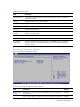
Boot Menu Figure 20 Boot Menu Table 18 Boot Menu fields Field Description Boot Device Priority Use this screen to specify the order in which the system checks for a boot device. Removable Drives Use this screen to view and configure removable drives in the system. Embedded NIC Port 1 PXE Use this screen to configure the embedded NIC Port 1 PXE boot option. The default is enabled. Embedded NIC Port 2 PXE Use this screen to configure the embedded NIC Port 2 PXE boot option. The default is enabled.
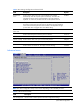
Figure 21 Boot Device Priority submenu NOTE: When you select a boot category from the boot menu, a list of devices in that category appears. For example, if the system has three hard disk drives connected, then the list will show all three hard disk drives attached. Removable Drives submenu Figure 22 Removable Drives submenu Security menu The Security menu allows users to set an administrator password. When entered, this password allows the user to access and change all settings in the Setup Utility.
Figure 23 Security menu This panel indicates whether or not an Administrator Password has been configured. To set an administrator password: 1. In the Security menu screen, in the Change Administrator Password field, press Enter. The Enter New Password window displays. Figure 24 Enter New Password 2. Type a new password in the Enter New Password box. The password may consist of up to eight alphanumeric characters (A-Z, a-z, 0-9), Next, press Enter, and the Confirm New Password window displays.
Figure 25 Confirm New Password 3. Retype the new password in the Confirm New Password box to verify the first entry, and then press Enter. The Password Installed OK windows display. Press OK to continue. Figure 26 Password installed 4. Press F10 to save the password and close the Setup Utility. To change the administrator password: 1. In the Security menu screen, in the Change Administrator Password field, press Enter. The Enter New Password window displays.
Figure 27 Password uninstalled submenu To check the administrator password: Figure 28 Password Check submenu Table 19 Password Check submenu fields Option Description Setup Set this value to check password when invoking the Setup utility. Always Set this value to check password when invoking Setup as well as on each boot.
Exit menu The Exit menu displays several options for how to quit the Setup Utility. Select any of the exit options and press Enter. Figure 29 Exit menu Table 20 Exit menu fields Option Description Save Changes and Exit Save the changes made and exit the Setup Utility Discard Changes and Exit Discard the changes and exit the Setup utility Discard Changes Discard any changes made thus far in the Setup utility. Load Option Default Loads the default settings for all BIOS setup fields.
It is recommended that you check this screen during the initial system setup and each time you install, remove, or upgrade accessories. You first need to enable the display of the diagnostic screen during bootup. Follow the steps below. To view the boot-time diagnostic screen: 1. In the Main menu screen, select Boot Options. 2. Select the BIOS Summary Display field. 3. Press the plus (+) or minus (-) key to set the field to Enabled. 4.
2. During POST, press F10 to access the Setup Utility. 3. Press F9 to load the default values. 4. Press F10 to save the changes and close the Setup Utility. Clearing CMOS You may need to clear the Setup configuration values (CMOS) if the configuration has been corrupted, or if incorrect settings made in the Setup Utility have caused error messages to be unreadable. Clearing the CMOS data removes the administrator password. The clear CMOS setting is on clear CMOS button (SW2) on the system board.
Error message 1 of 1: Error code 0103 Keyboard not detected - Keyboard error In some cases an error message may include recommendations for troubleshooting or require that you press the Enter key to display recommendations. Follow the instructions on the screen. Table 21 lists the most common POST error messages with their corresponding troubleshooting recommendation. It is recommended that you correct the error before proceeding, even if the server appears to boot successfully.
Table 21 POST Error Messages Error code Error message Description/corrective action 0271 Check date and time settings BIOS found date or time out of range and reset the RTC. May require setting legal date (1991-2099). Access Setup and check the values in the System Timeand System Datefields of the Main menu. 0280 Previous boot incomplete – Default configuration used Initial bootup failed. BIOS automatically loads the default system values, then boot again.
3. Short beeps are generated for the number in each group. Example: Test point 01Ah = 00 01 10 10 = 1-2-3-3 beeps Table 22 lists the checkpoint codes written at the start of each test and the beep codes issued for terminal errors.
Table 22 Beep codes and checkpoint codes Code Beep code Description 29h Initialize POST memory manager 2Ah Clear 512 KB base RAM 2Bh Initialize extended CMOS 2Ch 1-3-4-1 RAM failure on address line xxxx 2Eh 1-3-4-3 RAM failure on data bits xxxx of low byte of memory bus 2Fh Enable cache before system BIOS shadow 30h RAM failure on data bits xxxx of high byte of memory bus 32h Test processor bus-clock frequency 33h Initialize AMI Dispatch Manager 34h Test CMOS 35h Reinitialize regi
Table 22 Beep codes and checkpoint codes Code Beep code Description 54h Set key click if enabled 55h Enable USB devices 56h Enable keyboard 57h Enable FireWire devices 58h 2-2-3-1 Test for unexpected interrupts 59h Initialize POST display service 5Ah Display prompt ”Press F10 to enter SETUP” 5Bh Disable processor cache 5Ch Test RAM between 512 and 640 KB 5Eh Test base memory 60h Test extended memory 62h Test extended memory address lines 64h Jump to user patch 1 66h Configure
Table 22 Beep codes and checkpoint codes Code Beep code Description 84h Detect and install external parallel ports 85h Initialize PCI devices 86h Re-initialize onboard I/O ports 87h Configure system board configurable devices (optional) 88h Initialize BIOS data area 89h Enable non-maskable interrupts 8Ah Initialize extended BIOS data area 8Bh Test and initialize PS/2 mouse 8Ch Initialize floppy controller 8Eh Autotype hard drive size 8Fh Determine number of ATA drives (optional) 90
Table 22 Beep codes and checkpoint codes Code Beep code Description AEh Clear boot flag B0h Check for errors B1h Inform ROM pilot about the end of POST B2h POST done, prepare to boot operating system B3h Store extended CMOS B4h 1 One short beep before boot B5h Terminate quiet boot (optional) B6h Check password (optional) B7h Initialize ACPI BIOS B9h Prepare boot BAh Initialize SMBIOS BBh Initialize PnP option ROMs BCh Clear parity checkers BDh Display Multi-boot menu BEh Cl
POST-related troubleshooting Perform the following procedures when POST fails to run, error messages are displayed, or beep codes are emitted. If the POST failure is during a routine bootup, verify the following conditions: • • • All external cables and power cables are firmly plugged in. • • • • • The monitor's contrast and brightness settings are correct. The power outlet to which the server is connected is working. The server and monitor are both turned on.
Reprogramming the BIOS after the ROM disaster If the BIOS becomes corrupted, use the crisis recovery USB key to reprogram the BIOS. To reprogram the BIOS: 1. Perform the pre-installation procedures. 2. Connect a HP crisis recovery USB key to one of the USB ports on the server. 3. Power on the system, and then wait for approximately 10 minutes. 4. Reboot the system to verify that the system can boot normally. 5.
NOS installation Supported NOS Table 23 Supported network operating systems (NOS) NOS Version On-line information site Microsoft Windows Microsoft Windows Server 2003—Enterprise, Standard, and Web Editions Microsoft Windows Server 2003 R2—Enterprise, Standard, and Web Editions Microsoft Windows Server 2003 for 64-bit Microsoft World Wide Web access: www.microsoft.com Microsoft Product Support Services: http://support.microsoft.
• Note that most NOS installations remove all data from the hard disk on which they are installed. If you want to use additional hard disk drives to access existing data in the new server, HP recommends that you install and configure any of these hard drives after completing the NOS installation. • If you want to recycle used hard drives, use a utility such as fdisk to erase all data and partitions from that particular hard drive.
1. Insert one blank, formatted 3.5" diskette into the floppy drive. 2. Insert the Support CD into the optical media drive. By default, the Support CD automatically runs and displays the Welcome page. However, if this does not occur, double-click the Startup.htm file located on the root directory of the Support CD. 3. Follow the on-screen instructions to create the Windows NOS driver diskette. 4. Label, date, and save the driver diskette as HP disk [Windows NOS version]. Section 2.
9. At the Welcome to Windows dialog box, press Ctrl-Alt-Del, and then log on as Administrator. If you have successfully installed the Windows NOS, the Configure Your Server wizard launches. Close this window to postpone the customization of the server until all of the installation steps are completed. You can open the Configure Your Server wizard at any point by clicking Start | Programs .| Administrative Tools | Configure Your Server. Section 3.
2. Click the HP ProLiant DL185 Generation 5 server drivers for chipset, Network, and Video link. 3. Select the embedded VGA driver for the Windows [NOS version] option. The File Download dialog box displays. 4. Click Open to download the driver. The Security Warning dialog box displays. 5. Click Yes. The installation menu for the selected driver is displayed. 6. Follow the on-screen instructions to install the embedded VGA driver. 7. After completing the installation, reboot the server.
• Basic drives are used to create primary or local partitioned drives. To manage different drives and partitions: 1. Click Start | Programs | Administrative Tools | Computer Management. 2. Double-click Storage in the tree, and then click Disk Management. The Write Signature and Upgrade wizard starts if you have new hard drives with no signatures on them. 3. Follow the on-screen instructions to create the signature. 4.
Section 5. Configuring the network Phase 1 - Configuring the server’s IP address During the installation process, the system was configured to use DHCP. If no DHCP server is found on the network, the system autoconfigures a random IP address to start functioning. It is important that you configure the proper IP address to be able to communicate with the clients. 1. Right-click My Network Places | Properties, then double-click Local Area Connection on your server.
Phase 3 - Configuring the domain controller setup The Windows NOS manual calls this process "Promoting the server to a domain controller.” 1. Click Start | Programs | Administrative Tools | Configure Your Server. 2. Select Active Directory. 3. Scroll down and click Start the Active Directory wizard. 4. Click Next to continue. NOTE: The following instructions correspond to the standard steps for new domain creation. You may customize the options proposed by your Windows NOS to match your environment.
Section 6. Installing additional HP accessories The HP ProLiant DL185 Generation 5 Server Support CD includes the drivers for accessories compatible to your server. Refer to the product manual enclosed with the accessory for the detailed installation procedure and/or to the attached readme.txt file associated with the driver. The readme.txt file can be found on the appropriate driver diskette. Installing Red Hat Enterprise Linux NOS Installation flow 1. Install Red Hat Enterprise Linux [version].
Section 1. Launching the Red Hat Enterprise Linux installer 1. Turn on the server and insert the Red Hat Enterprise Linux CD 1. The system displays a text menu. 2. Press Enter to start the installation. 3. At the CD Found dialog box, click Skip. The Welcome to Red Hat Enterprise Linux page displays. 4. Click OK to proceed to the customization of your installation. Section 2.
Review and modify the selection as necessary, then click Next to continue. If you selected the Custom install option, pre-determined packages have already been selected. However, depending upon your network environment additional packages may be necessary. NOTE: Remember to select the appropriate package groups that match your network settings. For example, the DNS Name Server package may be required if you have set up your new server to be the DNS controller. Section 3.
Installing SUSE Linux Enterprise Server NOS The procedures in this section apply to the SUSE Linux Enterprise Server NOS, version 9 and 10. Installation flow 1. Install SUSE Linux Enterprise [version]. For the specific procedure for each SLE NOS version, refer to the following sections. 2. Install additional HP accessories. The HP ProLiant DL185 Generation 5 Server Support CD includes the drivers for accessories compatible to your server.
Installation Setting 1. Click New Installation, then click OK. The installer automatically enables the default settings. 2. Review the default installation settings and modify them to meet your network environment. 3. Click Accept to initialize the installation process. 4. Click Yes, install on the warning dialog box to start the file copying. You may be prompted to insert the rest of the SLES9 CD-ROMs, depending on the installation settings you have chosen.
3. Select Installation, then press Enter to proceed to the customization of your installation. Section 2. Customizing the Installation Language Select the language you prefer for the installation, then click Accept to continue. Media Check Skip this stage of the installation. Click Next to continue. License Agreement Read the license agreement. If the terms of the agreement are acceptable, click Yes, I agree to the license agreement, then click Next to continue.
Follow the prompt to add a new local user account, then click Next to continue. Release Note Review the release notes, then click Next to continue. Hardware Configuration Review the default hardware settings and modify them as necessary, then click Next to continue. Installation Completed Click Finish to reboot the system and proceed to the login window Installing Sun Solaris 10 Perform the procedures in this section to install Sun Solaris 10 to your ProLiant server. Pre-installation instructions 1.
3. Click Solaris, then press Enter. 4. Type 1 to select the Solaris Interactive Installation option. After a few minutes, the Proposed Window System Configuration for Installation list appears. These settings are incorrect and should be modified. 5. Press Esc to modify the settings and customize the installation. Section 2. Customizing the installation The Sun Solaris10 Installer shifts to a text-based screen for customizing the hardware selection and other options.
Set the system date and time. If the default date and time settings displayed are correct, click Next. Otherwise, adjust the date and time settings, then click Next. Click Geographic Continent/Country/Region, then click Next to continue. Root Password Enter a root password. Re-enter the password in the second box, then click Next to continue. Confirm Information A configuration information summary is displayed. Verify this information, then click Confirm to proceed to the installation proper. Section 3.
Ready to Install An installation information summary is displayed. Verify this information, then click Install Now to start the installation process. Upon completing the installation, the system automatically reboots. You can now eject the SS10U1 DVD. Once the system reboots, the new Sun Solaris environment is loaded.
Server management Pre- and post-installation procedures Pre-installation procedures WARNING: Failure to properly turn off the server before you open the server or before you start removing or installing hardware components may cause serious damage as well as bodily harm. WARNING: To reduce the risk of personal injury from hot surfaces, allow the chassis and any installed hardware components to cool before touching them.
Post-installation procedures 1. Be sure all components are installed according to the described step-by-step instructions. 2. Check to make sure you have not left loose tools or parts inside the server. 3. Reinstall any expansion boards, riser board assemblies, peripherals, board covers, brackets, and system cables that you have removed. 4. Reinstall the top cover: a. Place the cover on the chassis approximately 1.25 cm (0.5 in) toward the rear of the unit, then slide the cover forward into place.
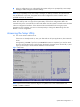
8. At the Password prompt, type your password and press Enter. The default password is admin. 9. The message CLP Session Initiated displays. 10. At the prompt, type cd map1/nic1 to navigate to the correct directory. The command line interface is SMASH-compliant. 11. Type show to display the current settings. 12. Modify the settings you want to change. NOTE: The set variables are case-sensitive. For example, by default, the BMC is set to use DHCP to get the IP address.
Index A I administrator password, 24 IDE, 13 administrator password changing, 26 IP subnet mask, 59 administrator password clearing, 26, 27 IPMI LAN interface, 59 AMIBIOS Setup Utility, 5 L asset tag, 9 ATA/IDE Configuration, 12 LAN Configuration, 17 LAN Controller, 59 B Load Option Default, 28 base I/O address, 28 M Baseboard management controller, 19 Basic Input/Output System, 5 beep codes, 32 BIOS EHCI Hand-Off, 22 BIOS overview, 5 memory, 9 N New Password box, 25 NOS pre-installation p
Summary Screen, 9 U Sun Solaris 10, 54 USB 2.