HP ProLiant DL170h G6 Server Installation Sheet Part Number 531486-004
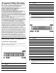
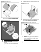
Item Description 4 Health LED of Node 2 5 Health LED of Node 4 6 Thumbscrews for rack mounting 7 Hard disk drive (HDD) activity LED 8 Hard disk drive (HDD) location/error LED 9 Hard disk drive (HDD) bay IMPORTANT: From the front side view, the right node is node 2 and the left node is node 4. Figure 2 Front panel components of a four Node system,16 SFF HDD cage with two optional front power/LED kit.
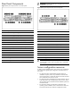
Rear Panel Components Figure 3 Rear panel components of a two Node system Item Description 1 PCIe Gen2 Full-height,full-length expansion card slot 2 PCIe Gen2 Full-height,half-length expansion card slot 3 PCIe Gen2 Low-profile expansion card slot 4 Server UID LED button 5 Shared 1Gb NIC2/Management Port (IPMI) (top) 6 1Gb NIC1 port (bottom) 7 T-10/T-15 driver 8 Dedicated Management Port (IPMI) (Optional)_ 9 USB 2.
• Refer to the HP ProLiant DL170h G6 Server Easy Set-up CD for additional information and updates not provided in this installation sheet. You can also access additional information and documentation from the HP website at http://www.hp.com/, either by connecting directly or through the Easy Set-up CD.
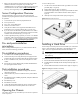
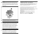
Installing a Memory Module Figure 8 Installing a memory module The following guidelines must be followed when memory modules are being added or replaced: 1. Up to 128GB, using PC3-8500R DDR3 Registered (RDIMM) memory, operating at 800MHz when fully populated in 16 slots. Up to 24GB, using PC3-10600E DDR3 Unbuffered (UDIMM) memory, operating at 1066MHz when fully populated at 2 DIMMs per Channel in 12 slots 2.
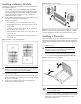
Figure 10 Reinserting the processor 4. Press the tabs on the processor installation tool to separate it from the processor, and then remove the tool. Figure 12 Removing the tool 3. Align the processor installation tool with the socket, and then install the processor. THE PINS ON THE SYSTEM BOARD ARE VERY FRAGILE AND EASILY DAMAGED. Figure 11 Installing the processor 5. Close the processor socket retaining bracket and the processor locking lever. The processor socket cover is automatically ejected.
CAUTION: To prevent the heat sink from tilting to one side during installation/removal, turn each screw a couple of turns, alternatively between both of them, and then apply the final torque. Do not over tighten the spring loaded screws to prevent them from breaking off. A maximum torque of 4.5 inch-lb is set for each screw. Figure 14 Installing the heat sink assembly CAUTION: Be sure that the heat sink sits squarely on the processor, or overheating and damage to the processor may occur.
Legal notices © Copyright 2009, 2011 Hewlett-Packard Development Company, L.P. The information contained herein is subject to change without notice. The only warranties for HP products and services are set forth in the express warranty statements accompanying such products and services. Nothing herein should be construed as constituting an additional warranty. HP shall not be liable for technical or editorial errors or omissions contained herein. Microsoft, Windows, and Windows NT are U.S.