
HP ProLiant SL170h G6 Server Installation Sheet

Identifying Chassis Components
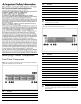
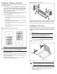
Front Panel Components
Figure 1 Front panel components of a two Node system,8 LFF HDD
cage with optional front power/LED kit
Item Description
1 Power button of Node 2
2 Chassis UID LED Button
3 Power button of Node 4
Item Description
4 Health LED of Node 2
5 Health LED of Node 4
6 Thumbscrews for rack mounting
7 Hard disk drive (HDD) activity LED
8 Hard disk drive (HDD) location/error LED
9 Hard disk drive (HDD) bay
IMPORTANT: From the front side view, the right node is node 2
and the left node is node 4.
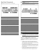
Figure 2 Front panel components of a four Node system,16 SFF HDD
cage with two optional front power/LED kit.
Item Description
1 Power button of Node 1
2 Chassis UID LED Button
3 Power button of Node 2
4 Health LED of Node 1
5 Health LED of Node 2
6 Power button of Node 3
7 Power button of Node 4
8 Health LED of Node 3
9 Health LED of Node 4
10 Thumbscrews for the rack mounting
11 Hard disk drive (HDD) activity LED
12 Hard disk drive (HDD) location/error LED
13 Hard disk drive (HDD) bay
IMPORTANT: From the front side view, the node in the top right
is node 1, bottom right is node 2, top left is node 3 and bottom
left is node 4.