
HP ProLiant SL170h G6 Server Installation Sheet

• Refer to the HP ProLiant DL170h G6 Server Easy Set-up CD for
additional information and updates not provided in this
installation sheet. You can also access additional information and
documentation from the HP website at http://www.hp.com/
,
either by connecting directly or through the Easy Set-up CD.
Server Configuration Overview
The steps listed below give an overview of the necessary setup
procedures for preparing the HP ProLiant DL170h Generation 6 Server
for operation:
1 Connect the AC power cord and peripheral devices.
2 Power up the server.
3 Press “F10” to enter BIOS setup.
4 Note the server BIOS version.
5 Verify the server BIOS version against the latest BIOS version
listed for this server on the HP website: http://www.hp.com.
6 If you do not have the latest BIOS, update the BIOS now. Refer to
the ProLiant DL170h G6 Server Maintenance and Service Guide
available on the HP website: http://www.hp.com.
7 Install a supported operating system of your choice. For detailed
procedures, refer to the documentation provided by the operating
system vendor. For a list of operating systems supported by your
ProLiant server, go to http://www.hp.com/go/supportos
.
Pre- and post-installation
procedures
When installing additional options in your HP ProLiant DL170h G6
Server, observe the following procedures:
Pre-installation procedures
1 Turn off the server and all the peripherals connected to it.
2 Disconnect the AC power cord(s) from the power supply connector
located on the server rear panel to reduce the risk of electrical shock.
3 If server is installed in a rack, remove server and place it on a flat
surface.
4 Remove the top cover by following the procedure described later in
the “Opening the Chassis” section.
Post-installation procedures
1 Be sure all components are installed according to the described
step-by-step instructions.
2 Check to make sure you have not left loose tools or parts inside the
server.
3 Reinstall the PCI cage, air baffle, peripherals, and system cables that
you have removed.
4 Reinstall the top cover.
5 Reinstall server into rack.
6 Connect all external cables and the AC power cord to the system.
7 Press the power button on the front panel to turn on the server.
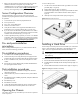
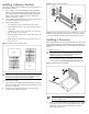
Opening the Chassis
You need to remove the top cover before you can remove or replace a
server component.
To remove the top cover:
1 Turn the screw to the side with the unlock sign with the T-10- wrench
provided. (Step 1 in Figure 5)
2 Pull the plastic button up. (Step 2 in Figure 5)
3 Slide the cover approximately 1.25 cm (0.5 in) toward the rear of the
unit and then lift the cover to detach it from the chassis. (Step 3 in
Figure 5)
4 Lift the top cover away from the chassis. (Step 4 in Figure 5)
Figure 5 Removing the top cover
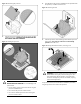
Installing a Hard Drive
The drive bays on the front panel can accommodate up to 16 SFF hard
drives or 8 LFF hard drives, depending on the selected drive cage
option. The server supports both SAS and SATA hard drives.
CAUTION: Drives can be damaged by static electricity. Before
handling drives, touch an unpainted metal surface to discharge
static electricity.
To install a hard drive in the chassis.
1 Remove the hard drive blank from the front of system if installed.
2 Push the hard drive assembly into the drive bay until it stops (Step 1 in
Figure 6)
3 Press the HDD carrier latch inward until it clicks. (Step 2 in Figure 6)
Figure 6 Installing the hard drive assembly