HP ProLiant DL320 Generation 2 Server Maintenance and Service Guide September 2003 (Fourth Edition) Part Number 293164-004
2003 Hewlett-Packard Development Company, L.P. Microsoft® and Windows NT® are U.S. registered trademarks of Microsoft Corporation. Intel® and Pentium® are U.S. registered trademarks of Intel Corporation. Hewlett-Packard Company shall not be liable for technical or editorial errors or omissions contained herein. The information in this document is provided “as is” without warranty of any kind and is subject to change without notice.
Contents About This Guide Audience Assumptions..................................................................................................................................v Technician Notes...........................................................................................................................................v Where to Go for Additional Help............................................................................................................... vii Integrated Management Log ...
Contents Fans..........................................................................................................................................................2-27 Cables.......................................................................................................................................................2-28 Two-Device Terminated SCSI Cable ................................................................................................2-28 ATA Cables.................................
About This Guide This maintenance and service guide can be used for reference when servicing an HP ProLiant DL320 Generation 2 server. WARNING: To reduce the risk of personal injury from electric shock and hazardous energy levels, only authorized service technicians should attempt to repair this equipment. Improper repairs can create conditions that are hazardous. Audience Assumptions This guide is for service technicians.
About This Guide CAUTION: To properly ventilate the system, you must provide at least 7.6 cm (3.0 in) of clearance at the front and back of the server. CAUTION: The computer is designed to be electrically grounded (earthed). To ensure proper operation, plug the AC power cord into a properly grounded AC outlet only. NOTE: Any indications of component replacement or printed wiring board modifications may void any warranty.
About This Guide Where to Go for Additional Help In addition to this guide, the following information sources are available: • User documentation • Service Quick Reference Guide • Service training guides • Service advisories and bulletins • QuickFind information services • Insight Manager software • HP Servers Troubleshooting Guide Integrated Management Log The server includes an integrated, nonvolatile management log that contains fault and management information.
1 Illustrated Parts Catalog This chapter provides the illustrated parts breakdown and spare parts list for the HP ProLiant DL320 Generation 2 server. The table in this chapter provides names and ordering numbers for all referenced spare parts.
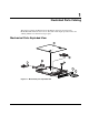
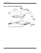
Illustrated Parts Catalog System Components Exploded View Figure 1-2: System components exploded view 1-2 HP ProLiant DL320 Generation 2 Server Maintenance and Service Guide
Illustrated Parts Catalog Mechanical Parts and System Components Spares List Table 1-1: Mechanical and System Spare Parts List Item Description Spare Part Number Mechanical Components 1 Access panel 307130-001 2 Fixed cable tray 173839-001 3 PCI riser board assembly 293365-001 4 Center wall bracket with fans 293366-001 Power 5 180-Watt power supply 293367-001 Boards 6 User interface board 207725-001 7 Optical device/diskette drive assembly backplane 336782-001 8 System board 29336
Illustrated Parts Catalog Table 1-1: Mechanical and System Spare Parts List continued Item Description Spare Part Number Miscellaneous 14 Replacement battery, 3-V lithium 234556-001 15 Two-device terminated SCSI cable (Ultra3)* 293373-001 16 Hard drive cable kit* 293372-001 a) ATA hard drive cables (2)* b) Optical device/diskette assembly drive cable* 17 Miscellaneous plastics kit 293374-001 a) Bezel b) Shipping/ejector key c) PCI card guide* d) Bezel screws* 18 Hardware kit 293375-001 a)
2 Removal and Replacement Procedures This chapter provides subassembly and module-level removal and replacement procedures for HP ProLiant DL320 Generation 2 servers. After completing all necessary removal and replacement procedures, run the diagnostics program to verify that all components operate properly.
Removal and Replacement Procedures Symbols on Equipment Any surface or area of the equipment marked with these symbols indicates the presence of a hot surface or hot component. WARNING: To reduce the risk of injury from a hot component, allow the surface to cool before touching it. To reduce the risk of injury from electric shock hazards, do not open this enclosure. WARNING: Any surface or area of the equipment marked with these symbols indicates the presence of electric shock hazards.
Removal and Replacement Procedures WARNING: To reduce the risk of personal injury or damage to the equipment, at least two people are needed to safely unload the rack from the pallet. An empty 42U rack weighs 115 kg (253 lb), is over 2.1 m (7 ft) tall, and may become unstable when being moved on its casters. Do not stand in front of the rack as it rolls down the ramp from the pallet. Handle the rack from both sides.
Removal and Replacement Procedures • Integrated ATA RAID controller module • Optical device/diskette drive assembly backplane • PCI riser board assembly • Expansion board • PCI card guide • Center wall • Cables — Two-device terminated SCSI cable — ATA cables — Optical device/diskette drive assembly cable 2-4 • Power supply • Battery • Memory modules • Processor • System board HP ProLiant DL320 Generation 2 Server Maintenance and Service Guide
Removal and Replacement Procedures Powering Down the Server The server does not completely power down when the front panel power button is pressed. The button toggles server power between On and Standby. In Standby, the server removes power from most electronics and drives, portions of the power supply and some internal circuitry remain active. To completely remove all power from the system, disconnect the power cord from the server.
Removal and Replacement Procedures To power down the server: 1. Press the power button to toggle the server to standby. The power LED above the power button changes from green to amber. 2. Listen for the fan noise to stop to indicate that the server is powered down. 3. Disconnect the power cord first from the AC outlet and then from the server. The power LEDs turn off. 4. Disconnect all remaining cables on the server rear panel, including cables extending from external connectors on expansion boards. 5.
Removal and Replacement Procedures To remove the access panel: 1. Power down the server. See “Powering Down the Server” in this chapter. 2. Press and hold down the locking latches (1). 3. Slide the access panel approximately 1.25 cm (0.5 in) toward the rear of the unit and lift the panel to remove it (2). Figure 2-1: Removing the access panel To replace the access panel, reverse steps 1 through 3.
Removal and Replacement Procedures Shipping/Ejector Key The server includes a shipping/ejector key that secures the optical device/diskette drive assembly or the bezel blank during shipping. This key should be removed before deploying the server. This key is also used to eject an assembly or the blank. CAUTION: Always install the shipping/ejector key in its storage location inside the chassis before shipping the server. Failure to do so can result in damage to the optical device/diskette drive assembly.
Removal and Replacement Procedures Bezel Blank To remove the bezel blank: 1. Power down the server. See “Powering Down the Server” in this chapter. 2. Remove the shipping/ejector key from the chassis if you have not already done so. See “Shipping/Ejector Key” in this chapter. 3. Insert the end of the shipping/ejector key approximately 1.25 cm (0.5 in) into the optical device/diskette drive assembly ejector port on the lower right corner of the server front panel (1) to eject the blank (2).
Removal and Replacement Procedures Optical Device/Diskette Drive Assembly The optical device/diskette drive assembly option is for either a CD-ROM/diskette drive or a DVD-ROM/diskette drive combination. The following procedure applies to both options. To remove the optical device/diskette drive assembly: 1. Power down the server. See “Powering Down the Server” in this chapter. 2. Remove the shipping/ejector key from the chassis if you have not already done so. See “Shipping/Ejector Key” in this chapter. 3.
Removal and Replacement Procedures Fully Seated Optical Device/Diskette Drive Assembly Figure 2-5: Fully seated optical device/diskette drive assembly (ejector key shown stored in ejector port) When frequent optical device/diskette drive assembly ejection is anticipated, leave the key in the ejector port for easy access, as shown in Figure 2-5. Otherwise, store the shipping/ejector key inside the chassis for future use.
Removal and Replacement Procedures Bezel To remove the bezel: 1. Power down the server. See “Powering Down the Server” in this chapter. 2. Remove the access panel. See “Access Panel” in this chapter. 3. If necessary, remove the optical device/diskette drive assembly or bezel blank. See “Optical Device/Diskette Drive Assembly,” or “Bezel Blank” in this chapter. 4. Remove the four screws that secure the bezel to each side of the chassis.
Removal and Replacement Procedures 5. Release the bezel from the chassis by pushing the tabs up from the inside front edge of the chassis (1). 6. Rotate the bezel away from the top edge of the chassis (2). 7. Lift the bezel off the locating tabs on the bottom edge of the chassis (3). IMPORTANT: Avoid damaging the light pipes on the user interface board when removing the bezel. Figure 2-7: Removing the bezel from the chassis To install the bezel, reverse steps 1 through 7, omitting step 5.
Removal and Replacement Procedures Hard Drive Overview The server contains two drive bays for either ATA or SCSI hard drives. There are two ATA channels and the server ships standard with two 1-inch drive trays and is preconfigured for two 1-inch ATA hard drives. The following sections provide general guidelines and installation procedures for installing or upgrading hard drives.
Removal and Replacement Procedures Guidelines for Installing SCSI Hard Drives Each SCSI hard drive installed in the server must be configured with a unique SCSI ID number. Unique identification allows the system to search for the lowest numbered drive to use as a bootable partition. By default, the jumpers on SCSI hard drives are set to ID 0 and may need to be reset when the drive is installed as an optional or replacement drive in the server.
Removal and Replacement Procedures Hard Drives To remove a hard drive from the hard drive bay: 1. Power down the server. See “Powering Down the Server” in this chapter. 2. Remove the access panel. See “Access Panel” in this chapter. 3. Disconnect the SCSI or ATA cables from the hard drives.
Removal and Replacement Procedures 4. Disconnect the power cables from the hard drives. Figure 2-10: Disconnecting the hard drive power cables 5. Remove the hard drive and hard drive tray: a. Loosen the thumbscrew that secures the hard drive tray to the chassis (1). b. Slide the tray toward the rear of the server and lift the tray out of the chassis (2).
Removal and Replacement Procedures 6. Remove the four 6-32 Phillips-head screws that secure the hard drive to the hard drive tray (1). 7. Remove the hard drive from the hard drive tray (2). Figure 2-12: Removing the hard drive from a hard drive tray CAUTION: Review “Guidelines for SCSI Hard Drives” and “Guidelines for ATA Hard Drives” in this chapter to ensure proper jumper settings and hard drive configuration.
Removal and Replacement Procedures Single Channel Wide Ultra3 SCSI Controller Module To remove the SCSI module: 1. Power down the server. See “Powering Down the Server” in this chapter. 2. Remove the access panel. See “Access Panel” in this chapter. CAUTION: Prevent damage to the connector pins by lifting the SCSI module evenly and with equal pressure on the board. Tilting the board causes the connector pins to bend. 3.
Removal and Replacement Procedures Optical Device/Diskette Drive Assembly Backplane To remove the optical device/diskette drive assembly backplane: 1. Power down the server. See “Powering Down the Server” in this chapter. 2. Remove the access panel. See “Server Access Panel” in this chapter. 3. Remove the shipping/ejector key. See “Shipping/Ejector Key” in this chapter. 4. Remove the optical device/diskette drive assembly or bezel blank.
Removal and Replacement Procedures User Interface Board To remove the user interface board: 1. Power down the server. See “Powering Down the Server” in this chapter. 2. Remove the access panel. See “Access Panel” in this chapter. 3. Remove the shipping/ejector key. See “Shipping/Ejector Key” in this chapter. 4. Remove the optical device/diskette drive assembly or bezel blank. See “Optical Device/Diskette Drive Assembly” or “Bezel Blank” in this chapter. 5.
Removal and Replacement Procedures PCI Riser Board Assembly To remove the PCI riser board assembly: 1. Power down the server. See “Powering Down the Server” in this chapter. 2. Remove the access panel. See “Access Panel” in this chapter. 3. Disconnect any cables connecting an existing expansion board to the system board. 4. Loosen the PCI riser board thumbscrew (1). 5. Lift and remove the assembly from the server chassis (2).
Removal and Replacement Procedures Expansion Board To remove an expansion board: CAUTION: To avoid the risk of damage to the system or expansion boards, remove all power cords before installing or removing an expansion board. When the front panel power switch is off, auxiliary power is still connected to the PCI expansion slot and may damage the card. 1. Power down the server. See “Powering Down the Server” in this chapter. 2. Remove the access panel. See “Access Panel” in this chapter. 3.
Removal and Replacement Procedures PCI Card Guide To remove a PCI card guide: 1. Power down the server. See “Powering Down the Server” in this chapter. 2. Remove the access panel. See “Access Panel” in this chapter. 3. Remove the PCI riser board assembly. See “PCI Riser Board Assembly” in this chapter. 4. Remove the expansion board. See “Expansion Board” in this chapter. 5. Press and hold the guide latch to release the PCI card guide (1). 6.
Removal and Replacement Procedures Center Wall To remove the center wall: 1. Power down the server. See “Powering Down the Server” in this chapter. 2. Remove the access panel. See “Access Panel” in this chapter. 3. Remove the PCI riser board assembly. See “PCI Riser Board Assembly” in this chapter. WARNING: To reduce the risk of personal injury from hot surfaces, allow the internal system components to cool before touching them. 4.
Removal and Replacement Procedures 5. Loosen the center wall thumbscrew (1). 6. Push in and hold the tab next to the center wall fans to unlock the center wall from the chassis (2). 7. Raise the locking end of the center wall from the chassis (3). Figure 2-20: Unlocking the center wall 8. Rotate the center wall to clear the center wall alignment tab from the alignment slot (1), and lift the center wall out of the chassis (2).
Removal and Replacement Procedures Fans The server contains six fans. Four fans are located on the center wall, and two are located in the power supply unit. IMPORTANT: A “Fan 5 Error” indicates an error from either one of the fans located in the power supply. When this error occurs, replace the entire power supply unit. Use the following figure and table to locate the system fans.
Removal and Replacement Procedures Cables The following sections of this guide contain removal and replacement procedures for the standard cables that ship with the server: • Two-Device Terminated SCSI cable • ATA cables • Optical Device/Diskette Drive Assembly cable Two-Device Terminated SCSI Cable To remove the two-device terminated SCSI cable: 1. Power down the server. See “Powering Down the Server” in this chapter. 2. Remove the access panel. See “Access Panel” in this chapter. 3.
Removal and Replacement Procedures ATA Cables To remove the ATA cables: 1. Power down the server. See “Powering Down the Server” in this chapter. 2. Remove the access panel. See “Access Panel” in this chapter. 3. Remove the PCI riser board assembly. See “PCI Riser Board Assembly” in this chapter. 4. Remove the center wall. See “Center Wall” in this chapter. 5. Disconnect the ATA cable from the secondary ATA controller (1) and hard drive connector (2). 6.
Removal and Replacement Procedures Optical Device/Diskette Drive Assembly Cable To remove the optical device/diskette drive assembly cable: 1. Power down the server. See “Powering Down the Server” in this chapter. 2. Remove the access panel. See “Access Panel” in this chapter. 3. Remove the PCI riser board assembly. See “PCI Riser Board Assembly” in this chapter. 4. Remove the center wall. See “Center Wall” in this chapter. 5.
Removal and Replacement Procedures Power Supply IMPORTANT: A “Fan 5 Error” indicates an error from one of the fans located in the power supply. When this error occurs, replace the entire power supply unit. To remove the power supply: 1. Power down the server. See “Powering Down the Server” in this chapter. 2. Remove the access panel. See “Server Access Panel” in this chapter. 3. Remove the PCI riser board assembly. See “PCI Riser Board Assembly” in this chapter. 4. Remove the center wall.
Removal and Replacement Procedures Battery If the server no longer automatically displays the correct date and time, check the battery that provides power to the real-time clock. If necessary, replace a used battery with a CR2032 lithium battery. Under normal use, battery life is at least 5 years. WARNING: This server contains either an internal lithium manganese dioxide, or a vanadium pentoxide battery. There is a risk of fire and burns if the battery pack is not handled properly.
Removal and Replacement Procedures To remove the battery: 1. Power down the server. See “Powering Down the Server” in this chapter. 2. Remove the access panel. See “Access Panel” in this chapter. 3. Locate the battery on the system board. Figure 2-27: Locating and removing the system battery 4. If necessary, remove the PCI riser board assembly to access the battery location. See “PCI Riser Board Assembly” in this chapter. 5. Press the battery release lever away from the battery (1). 6.
Removal and Replacement Procedures Memory Modules The server supports up to four PC2100 DDR ECC registered 266-MHz SDRAM DIMMs installed in four sockets on the system board. NOTE: Populate the DIMM sockets in descending sequential order, starting with DIMM socket 4.
Removal and Replacement Procedures Observe the following guidelines when installing additional memory: • DIMMs must be industry-standard, 128-MB, 256-MB, 512-MB, or 1-GB, 3-cm (1.2-in), 184-pin PC2100, 266-MHz DDR ECC memory DIMMs. The DDR memory DIMMs must support CAS Latency 2, where CL=2 or greater. They must also contain the mandatory Joint Electronic Device Engineering Council (JEDEC) Serial Presence Detect (SPD) information. • DIMMs installed in the server must be registered DDR, 2.
Removal and Replacement Procedures 6. To install a DIMM, gently push the DIMM into the socket on the system board (1). As the DIMM enters the socket and is properly seated, the latches close (2). Figure 2-30: Installing a DIMM in a DIMM socket CAUTION: Use only HP supplied DIMMs. DIMMs from other sources can adversely affect data integrity. 7. Press down firmly on the DIMM while pushing the latches inward until the latches snap into place.
Removal and Replacement Procedures Processor CAUTION: Always use a new heatsink when replacing processors. Failure to use new components can cause damage to the processor. To remove the processor: 1. Power down the server. See “Powering Down the Server” in this chapter. 2. Remove the access panel. See “Access Panel” in this chapter. 3. Locate the processor on the system board.
Removal and Replacement Procedures 4. Disengage the retaining clips on each side of the heatsink. Figure 2-32: Disengaging the heatsink retaining clips (one on each side) 5. Remove the heatsink from the top of the processor.
Removal and Replacement Procedures 6. Lift the processor locking lever (1) and lift the processor from the socket (2). Figure 2-34: Removing the processor from the system board Reverse steps 1 through 6 to reinstall the processor and heatsink. CAUTION: Always use a new heatsink when replacing processors. Failure to use new components may result in damage to the processor.
Removal and Replacement Procedures System Board To remove the system board: 1. Power down the server. See “Powering Down the Server” in this chapter. 2. Remove the access panel. See “Access Panel” in this chapter. 3. Remove the PCI riser board assembly. See “PCI Riser Board Assembly” in this chapter. 4. Disconnect the fan cables 1 through 4. See “Fans” in this chapter. 5. Remove the center wall. See “Center Wall” in this chapter. 6. Remove the SCSI module (if installed).
Removal and Replacement Procedures 12. Remove the processor. See “Processor” in this chapter. CAUTION: Always use a new heatsink when replacing processors on the system. Failure to use new components may result in damage to the processor. See “Processor” in this chapter. 13. Identify the alignment keys and keyhole locations, 1 through 6, on the system board.
Removal and Replacement Procedures 14. Remove all Phillips head screws that secure the system board to the chassis (1). 15. Slide the system board 0.7 mm (0.25 in) toward the front of the chassis, ensuring that the board unseats from all the alignment keys, and lift the board up and away from the keys (2). Figure 2-36: Removing the system board Reverse steps 1 through 14 to replace the system board. IMPORTANT: The server serial number must be re-entered through RBSU after replacing the system board.
Removal and Replacement Procedures 5. Press the Escape key to exit RBSU. 6. Press the F10 key to confirm exiting RBSU. The server will automatically reboot.
3 Diagnostic Tools This chapter provides an overview of the software and firmware diagnostic tools available for HP ProLiant DL320 Generation 2 servers. Diagnostic Tools Utility Overview The following utilities assist in diagnosing problems, testing hardware, and monitoring and managing server operations. Table 3-1: Diagnostic Tools Tool What it is How to run it LX32 Enterprise Diagnostics A tool to assist testing and/or verifying operation of hardware.
Diagnostic Tools Table 3-1: Diagnostic Tools continued Tool What it is How to run it Survey Utility An online information-gathering agent that runs on servers to collect critical hardware and software information from various sources. Install the Survey Utility from SmartStart, or the Management CD.
Diagnostic Tools Table 3-1: Diagnostic Tools continued Tool What it is How to run it ROM-Based Setup Utility (RBSU) A utility used to configure the hardware installed in or connected to the server. Specifically, it can: Run RBSU directly by pressing the F9 key during POST. Automatic Server Recovery (ASR) ROMPaq Utility • Resolve resource conflicts in areas such as memory, port addresses, and interrupts (IRQs). • Configure PCI boards automatically. • Provide switch and jumper settings.
4 Connectors, Switches, and LED Indicators This chapter contains illustrations and tables identifying and describing connectors, switches, and LED indicator locations on the front panel, rear panel, system board, and hard drives for the HP ProLiant DL320 Generation 2 server.
Connectors, Switches, and LED Indicators Connectors This section contains figures and tables showing connector locations on the front panel, rear panel, PCI riser board assembly, and the system board of the server. Rear Panel Connectors The following figure and table show the connectors on the rear panel of the server.
Connectors, Switches, and LED Indicators Expansion Slot Connector The following figure and table shows the PCI expansion board slot connector and expansion board slot cover.
Connectors, Switches, and LED Indicators System Board Connectors The following figure and table show system board connectors on the system board.
Connectors, Switches, and LED Indicators System Switches The server has a switch bank (SW1) for system configuration and a non-maskable interrupt (NMI) switch that is used in the event of a service emergency that requires a complete data dump prior to restarting the operating system. Refer to the labels on the inside of the server access panel or to the following sections for the proper switch settings. The following figure and table show the location of the system switches.
Connectors, Switches, and LED Indicators System Configuration Switch (SW1) The system configuration switch (SW1) is an eight-position switch used for system configuration. Refer to the labels attached to the inside of the server access panel for proper system configuration settings. The following table shows the shipping system configuration switch settings of SW1.
Connectors, Switches, and LED Indicators LED Indicators This section contains illustrations and descriptions for the following internal and external server LEDs: • Front panel • Rear panel • System board Front Panel LED Indicators Front panel status LEDs allow constant monitoring of basic system functions while the server is operating.
Connectors, Switches, and LED Indicators Table 4-6: Front Panel LEDs continued 4-8 Item LED Description Status 3 NIC 1 link/activity On = Link Off = No link Blinking = Activity 4 System health Green = Good Amber = Degraded Red = Critical error 5 Hard drive activity On = Activity Off = No activity 6 Power On/Off Green = Power on Amber = Standby Off = Power off 7 Optical drive activity On = Activity Off = No activity HP ProLiant DL320 Generation 2 Server Maintenance and Service Guide
Connectors, Switches, and LED Indicators Rear Panel LED Indicators The server rear panel contains three LEDs that allow monitoring of network activity and server identification.
Connectors, Switches, and LED Indicators Internal LED Indicator The system board contains an internal power status LED for use during troubleshooting operations. When the LED is illuminated, adequate power is available to the system from the power supply. If the LED is not illuminated, either the power cord is not connected or the power supply has failed.
5 Specifications This chapter provides operating and performance specifications for HP ProLiant DL320 Generation 2 server components and optional hardware, including: • System unit • Power supply • Memory • CD-ROM/diskette drive assembly — Low-profile 1.44-MB diskette drive — Low-profile IDE CD-ROM drive • DVD-ROM/diskette drive assembly — Low-profile 1.
Specifications System Unit Table 5-1: System Unit Specifications Item Description Height 4.19 cm (1.65 in) Depth 65.45 cm (25.75 in) Width 42.55 cm (16.75 in) Weight (maximum) 11.81 kg (26 lb) Weight (no drives installed) 9.54 kg (21 lb) U.S. and international input voltage requirements Rated input voltage 100 VAC to 240 VAC Rated input frequency 50 Hz to 60 Hz Rated input current 2.8 A (110 V) to 1.4 A (220 V) Rated input power 307 W Maximum peak power 200 W (for max.
Specifications Power Supply Table 5-2: Power Supply Specifications Item Description Input voltage specifications Rated input voltage 100 VAC to 240 VAC Rated input line 180 VAC to 264 VAC (90 VAC to 132 VAC) Frequency range 47 to 63 Hz Rated input power 307 W Rated input current 3.3 A, 1.
Specifications Optical Device/Diskette Drive Assembly Low-Profile 1.44-MB Diskette Drive Table 5-4: Low-Profile 1.44-MB Diskette Drive Specifications Item Description Size 8.89 cm (3.5 in) LED (front panel) Green Read/write capacity per diskette (high/low density) 1.44 MB/720 KB Drives supported 1 Drive height 1.52 cm (0.
Specifications Low-Profile IDE CD-ROM Drive Table 5-5: Low-Profile IDE CD-ROM Drive Specifications Item Description Applicable disk formats CD-DA, CD-ROM (mode 1 and 2); CD-XA (mode 2, Form 1 and 2), CD-1 Ready; CD-Extra; Photo CD (single and multiple session); CDi ready Capacity 550 MB (mode 1, 12 cm) 640 MB (mode 2, 12 cm) Block size 2638, 2352 bytes (mode 0); 2352, 2340, 2336, 1024 bytes (mode 1); 2352, 2340, 2336, 2048, 1024 bytes (mode 2) Dimensions Height 1.27 cm (0.5 in) Depth 13.
Specifications Low-Profile IDE DVD-ROM Drive Table 5-6: Low-Profile IDE DVD-ROM Drive Specifications Item Description Applicable disk formats DVD (single and double layer), DVD-5, DVD-9, DVD-10, DVD-R, CD-ROM (mode 1 and 2), CD-DA, CD-XA (mode 2, Form 1 and 2), CD-I (Mode 2, Form 1 & 2), CD-I Ready, CD-Bridge, CD-R, Photo CD (single and multiple session) Disc diameter 12 cm, 8 cm (4.72 in, 3.15 in) Capacity 4.7 GB (DVD-5) 8.5 GB (DVD-9) 9.
Specifications Single Channel Wide Ultra3 SCSI Controller Module Table 5-7: Single Channel Wide Ultra3 SCSI Controller Module Specifications Item Description Temperature range (non-condensing) Operating 10°C to 35°C (50°F to 95°F) Shipping -20°C to 50°C (-4°F to 122°F) Relative humidity (non-condensing) Operating 8% to 90% Non-operating 5% to 95% Maximum drives supported Up to 15 per channel Logical drives supported 15 Simultaneous drive transfer channels 1 Data transfer method 64-bit PCI
Specifications Integrated Ultra ATA/100 Controller Table 5-8: Ultra ATA/100 Controller Specifications Item Description Temperature range (non-condensing) Operating 0°C to 70°C (32°F to 158°F) Shipping -40°C to 125°C (-40°F to 257°F) Relative humidity (non-condensing) 5-8 Operating 10% to 90% Non operating 5% to 95% Simultaneous drive transfer channels 2 channels Transfer rate synchronous (Max) 100 MBps Data transfer method 32-bit PCI bus master Drive support Ultra ATA, EIDE & Fast ATA-2
Specifications Optional Hard Drives Ultra3 SCSI Hard Drives Table 5-9: Ultra3 SCSI Hard Drive Specifications Item 9.1 GB 18.2 GB Formatted capacity 9,100 MB 18,209 MB Height Third, 2.54 cm (1.0 in) Third, 2.54 cm (1.0 in) Size 8.89 cm (3.5 in) 8.89 cm (3.5 in) Interface Ultra3 SCSI Ultra3 SCSI Transfer rate synchronous (maximum) 160 MBps 160 MBps Single track 0.8 ms 0.8 ms Average 5.4 ms 7.5 ms Full stroke 12.2 ms 16.
Specifications ATA Hard Drives Table 5-10: ATA Hard Drive Specifications 40 GB 80 GB Formatted capacity 40,021 MB 80,026 MB Height Third, 2.54 cm (1.0 in) Third, 2.54 cm (1.0 in) Size 8.89 cm (3.5 in) 8.89 cm (3.5 in) Interface ATA/100 ATA/100 Transfer rate synchronous (max) 100 MBps 100 MBps Single track 0.8 ms 0.8 ms Average 5.4 ms 7.5 ms Full stroke 12.2 ms 16.0 ms Rotational speed 7,200 ±0.1% rpm 7,200 ±0.
Specifications Integrated NC7760 Gigabit Server Auto-Switching Network Interface Controller (NIC) Table 5-11: Integrated NC7760 Gigabit Server Auto-Switching Network Interface Controller (NIC) Specifications Item Description Network interface 10Base-T/100Base-TX/1000Base-T Ethernet Compatibility IEEE 802.2, 802,3, 803.
Index A access panel locking latches 2-7 part number 1-3 part numbers 1-3 removing 2-6 ASR See Automatic Server Recovery ATA cables installing 2-29 removing 2-29 ATA hard drives cables, part number 1-4 device numbers 2-15 guidelines 2-14 jumper settings 2-14 LEDs, activity 4-8 part number 1-3 population order 2-15 removing 2-16 specifications 5-10 Automatic Server Recovery (ASR) description 3-3 running 3-3 B battery disposal 2-32 life 2-32 part number 1-4 warnings 2-32 battery disposal, caution 2-32 bezel
Index HP only 2-36 removal procedure 2-35 socket identification 2-34 socket population order 2-35 sockets, location 4-4 disconnecting center wall fans 2-25 hard drive power cable 2-17, 2-31 optical device/diskette drive assembly backplane cable 2-20 optical device/diskette drive assembly cable 2-30 power supply cable 2-31 SCSI cable 2-28 diskette drive, specifications 5-4 drivers, updating 3-2 DVD-ROM drive, specifications 5-6 DVD-ROM/diskette drive assembly, part number 1-3 E ejector port 2-10 ejector po
Index guidelines for SCSI hard drives 2-15 obtaining 3-3 NMI switch See non-maskable interrupt (NMI) switch non-maskable interrupt (NMI) switch, location 4-5 K keyboard connector 4-2 kits hard drive cable 1-4 hardware, part number 1-4 miscellaneous plastics, part number 1-4 rack mounting, fixed rails, part number 1-4 L LED indicators See LEDs LEDs descriptions 4-7 to 4-10 drive activity 4-8 front panel 4-7 front unit identification (UID) 4-7 internal 4-10 network activity 4-9 network, link/activity 4-8,
Index removing 2-31 specifications 5-3 temperature range 5-3 voltage input 5-3 power supply cable, disconnecting 2-31 powering down the server 2-5 Power-On Self-Test (POST) 3-1 processor locating 2-37 part number 1-3 removing 2-37 socket location 4-4 socket, locating 2-37 socket, populating 2-37 resource conflict, resolving 3-3 retaining clip, optical device/diskette drive assembly backplane 2-20 return kit, part number 1-4 RJ-45 connectors, location 4-2 ROM-Based Setup Utility (RBSU) configuring after ba
Index NIC 5-11 power supply 5-3 SCSI hard drives 5-9 SCSI module See specifications, Single Channel Wide Ultra3 SCSI controller module Single Channel Wide Ultra3 SCSI controller module 5-7 system unit 5-2 status indicators See LEDs storage devices, part number 1-3 Survey Utility description 3-2 installing 3-2 SW1 See system configuration switch (SW1) switch settings, obtaining 3-3 switches non-maskable interrupt (NMI) described 4-6 function 4-5 non-maskable interrupt (NMI), location 4-5 Power On/Off 2-6 sy