HP ProLiant DL320 Generation 5 Server Maintenance and Service Guide Part Number 419195-003 March 2009 (Third Edition)
© Copyright 2006, 2009 Hewlett-Packard Development Company, L.P. The information contained herein is subject to change without notice. The only warranties for HP products and services are set forth in the express warranty statements accompanying such products and services. Nothing herein should be construed as constituting an additional warranty. HP shall not be liable for technical or editorial errors or omissions contained herein. Microsoft and Windows are U.S.
Contents Customer self repair ...................................................................................................................... 5 Parts only warranty service ......................................................................................................................... 5 Illustrated parts catalog ............................................................................................................... 16 Mechanical components.............................................
Server cable routing ................................................................................................................................ 58 Embedded SATA controller cable routing ................................................................................................... 58 Optional SAS/SATA controller cable routing .............................................................................................. 59 Slot 2......................................................................
Customer self repair HP products are designed with many Customer Self Repair (CSR) parts to minimize repair time and allow for greater flexibility in performing defective parts replacement. If during the diagnosis period HP (or HP service providers or service partners) identifies that the repair can be accomplished by the use of a CSR part, HP will ship that part directly to you for replacement. There are two categories of CSR parts: • Mandatory—Parts for which customer self repair is mandatory.
• Obligatoire - Pièces pour lesquelles la réparation par le client est obligatoire. Si vous demandez à HP de remplacer ces pièces, les coûts de déplacement et main d'œuvre du service vous seront facturés. • Facultatif - Pièces pour lesquelles la réparation par le client est facultative. Ces pièces sont également conçues pour permettre au client d'effectuer lui-même la réparation.
NOTA: alcuni componenti HP non sono progettati per la riparazione da parte del cliente. Per rispettare la garanzia, HP richiede che queste parti siano sostituite da un centro di assistenza autorizzato. Tali parti sono identificate da un "No" nel Catalogo illustrato dei componenti. In base alla disponibilità e alla località geografica, le parti CSR vengono spedite con consegna entro il giorno lavorativo seguente.
anrufen und sich von einem Mitarbeiter per Telefon helfen lassen. Den Materialien, die mit einem CSRErsatzteil geliefert werden, können Sie entnehmen, ob das defekte Teil an HP zurückgeschickt werden muss. Wenn es erforderlich ist, das defekte Teil an HP zurückzuschicken, müssen Sie dies innerhalb eines vorgegebenen Zeitraums tun, in der Regel innerhalb von fünf (5) Geschäftstagen.
Centro de asistencia técnica de HP y recibirá ayuda telefónica por parte de un técnico. Con el envío de materiales para la sustitución de componentes CSR, HP especificará si los componentes defectuosos deberán devolverse a HP. En aquellos casos en los que sea necesario devolver algún componente a HP, deberá hacerlo en el periodo de tiempo especificado, normalmente cinco días laborables. Los componentes defectuosos deberán devolverse con toda la documentación relacionada y con el embalaje de envío.
periode, gewoonlijk vijf (5) werkdagen, retourneren aan HP. Het defecte onderdeel moet met de bijbehorende documentatie worden geretourneerd in het meegeleverde verpakkingsmateriaal. Als u het defecte onderdeel niet terugzendt, kan HP u voor het vervangende onderdeel kosten in rekening brengen. Bij reparatie door de klant betaalt HP alle verzendkosten voor het vervangende en geretourneerde onderdeel en kiest HP zelf welke koerier/transportonderneming hiervoor wordt gebruikt.
Serviço de garantia apenas para peças A garantia limitada da HP pode incluir um serviço de garantia apenas para peças. Segundo os termos do serviço de garantia apenas para peças, a HP fornece as peças de reposição sem cobrar nenhuma taxa. No caso desse serviço, a substituição de peças CSR é obrigatória. Se desejar que a HP substitua essas peças, serão cobradas as despesas de transporte e mão-de-obra do serviço.
Customer self repair 12
Customer self repair 13
Customer self repair 14
Customer self repair 15
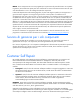
Illustrated parts catalog Mechanical components Item Description Spare part number Customer self repair (on page 5) 1 Access panel 432934-001 Mandatory1 2 Front bezel 432935-001 Mandatory1 3 Hard drive blank 413960-001 Mandatory1 Mandatory—Parts for which customer self repair is mandatory. If you request HP to replace these parts, you will be charged for the travel and labor costs of this service. 2 Optional—Parts for which customer self repair is optional.
Mandatory: Obbligatorie—Parti che devono essere necessariamente riparate dal cliente. Se il cliente ne affida la riparazione ad HP, deve sostenere le spese di spedizione e di manodopera per il servizio. 2 Optional: Opzionali—Parti la cui riparazione da parte del cliente è facoltativa. Si tratta comunque di componenti progettati per questo scopo. Se tuttavia il cliente ne richiede la sostituzione ad HP, potrebbe dover sostenere spese addizionali a seconda del tipo di garanzia previsto per il prodotto.
Illustrated parts catalog 18
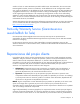
System components Item Description Spare part number Customer self repair (on page 5) System components 4 Fan assembly 432933-001 Optional2 5 Power supply, 420-W 432932-001 Optional2 Boards 6 Power button/LED board 432931-001 Optional2 7 System board 432924-001 Optional2 8 SAS/SATA backplane 432926-001 Optional2 9 Processors — — a) 3.2-GHz Intel® Celeron® D 352 processor, 512-KB L2 cache, 533-MHz FSB 418779-001 Optional2 b) 1.
Item Description Spare part number Customer self repair (on page 5) f) 3.
Item Description Spare part number Customer self repair (on page 5) 25 Optical drive cable* 433137-001 Optional2 26 Diskette drive cable* 433138-001 Optional2 27 USB cable* 432938-001 Optional2 28 Cable management arm kit* 360105-001 Mandatory1 29 Rack-mounting hardware kit* 360104-001 Mandatory1 *Not shown 1 Mandatory—Parts for which customer self repair is mandatory. If you request HP to replace these parts, you will be charged for the travel and labor costs of this service.
No: No—Algunos componentes no están diseñados para que puedan ser reparados por el usuario. Para que el usuario haga valer su garantía, HP pone como condición que un proveedor de servicios autorizado realice la sustitución de estos componentes. Dichos componentes se identifican con la palabra “No” en el catálogo ilustrado de componentes. 3 Mandatory: Verplicht—Onderdelen waarvoor Customer Self Repair verplicht is.
Removal and replacement procedures Required tools You need the following items for some procedures: • T-10/T-15 Torx screwdriver (included with the server) • HP Insight Diagnostics software ("HP Insight Diagnostics" on page 62) Safety considerations Before performing service procedures, review all the safety information. Preventing electrostatic discharge To prevent damaging the system, be aware of the precautions you need to follow when setting up the system or handling parts.
This symbol on an RJ-45 receptacle indicates a network interface connection. WARNING: To reduce the risk of electric shock, fire, or damage to the equipment, do not plug telephone or telecommunications connectors into this receptacle. This symbol indicates the presence of a hot surface or hot component. If this surface is contacted, the potential for injury exists. WARNING: To reduce the risk of injury from a hot component, allow the surface to cool before touching.
Server warnings and cautions Before installing a server, be sure that you understand the following warnings and cautions. WARNING: To reduce the risk of electric shock or damage to the equipment: • Do not disable the power cord grounding plug. The grounding plug is an important safety feature. • Plug the power cord into a grounded (earthed) electrical outlet that is easily accessible at all times. • Unplug the power cord from the power supply to disconnect power to the equipment.
2. Disconnect all peripheral cables and power cords from the server rear panel. 3. Loosen the thumbscrews that secure the server faceplate to the front of the rack. 4. Extend the server on the rack rails until the server rail-release latches engage. WARNING: To reduce the risk of personal injury or equipment damage, be sure that the rack is adequately stabilized before extending a component from the rack.
6. Disengage the server from the rack. For more information, refer to the documentation that ships with the rack mounting option. 7. Place the server on a sturdy, level surface. Access panel WARNING: To reduce the risk of personal injury from hot surfaces, allow the drives and the internal system components to cool before touching them. CAUTION: To prevent damage to electrical components, properly ground the server before beginning any installation procedure. Improper grounding can cause ESD. 1.
To replace the component, reverse the removal procedure. When adding hard drives to the server, observe the following general guidelines: • The system automatically sets all drive numbers. • If only one hard drive is used, install it in the bay with the lowest drive number. • Drives must be the same capacity to provide the greatest storage space efficiency when drives are grouped together into the same drive array. Optional storage controllers provide support for hot-plug capability and drive LEDs.
2. Extend the server from the rack (on page 25). 3. Remove the access panel ("Access panel" on page 27). 4. Disconnect all cables connected to the SAS/SATA backplane. 5. Remove all hard drives ("Hard drives" on page 27). 6. Remove all hard drive blanks ("Hard drive blanks" on page 28). 7. Remove the SAS/SATA backplane. To replace the component, reverse the removal procedure. Air baffle To install the component: 1. Power down the server (on page 26). 2.
3. Remove the access panel ("Access panel" on page 27). 4. Remove the air baffle. To replace the component, reverse the removal procedure. Fan assembly To remove the component: 1. Power down the server (on page 26). 2. Extend the server from the rack (on page 25). 3. Remove the access panel ("Access panel" on page 27). 4. Remove the air baffle ("Air baffle" on page 29). 5. Disconnect the fan cables from the system board. 6. Remove the fan assembly.
BBWC battery holder To remove the component: 1. Power down the server (on page 26). 2. Extend the server from the rack (on page 25). 3. Remove the access panel ("Access panel" on page 27). 4. Remove the air baffle ("Air baffle" on page 29). 5. Remove the fan assembly ("Fan assembly" on page 30). 6. Disconnect cables from any devices installed in the media cage, if necessary. 7. Remove the BBWC battery holder. To replace the component, reverse the removal procedure.
8. Remove the BBWC holder and battery. To replace the component, reverse the removal procedure. Media cage To remove the component: CAUTION: To prevent improper cooling and thermal damage, do not operate the server unless all bays are populated with either a component or a blank. 1. Power down the server (on page 26). 2. Extend the server from the rack (on page 25). 3. Remove the access panel ("Access panel" on page 27). 4. Remove the air baffle ("Air baffle" on page 29). 5.
9. Remove the media cage. To replace the component, reverse the removal procedure. Optical drive To remove the component: CAUTION: To prevent improper cooling and thermal damage, do not operate the server unless all bays are populated with either a component or a blank. 1. Power down the server (on page 26). 2. Extend the server from the rack (on page 25). 3. Remove the access panel ("Access panel" on page 27). 4. Remove the air baffle ("Air baffle" on page 29). 5.
10. Remove the optical drive. To replace the component, reverse the removal procedure. Diskette drive To remove the component: CAUTION: To prevent improper cooling and thermal damage, do not operate the server unless all bays are populated with either a component or a blank. 1. Power down the server (on page 26). 2. Extend the server from the rack (on page 25). 3. Remove the access panel ("Access panel" on page 27). 4. Remove the air baffle ("Air baffle" on page 29). 5.
10. Remove the diskette drive. To replace the component, reverse the removal procedure. Front video connector To remove the component: CAUTION: To prevent improper cooling and thermal damage, do not operate the server unless all bays are populated with either a component or a blank. 1. Power down the server (on page 26). 2. Extend the server from the rack (on page 25). 3. Remove the access panel ("Access panel" on page 27). 4. Remove the air baffle ("Air baffle" on page 29). 5.
10. Remove the front video connector. To replace the component, reverse the removal procedure. Power button/LED board To remove the component: 1. Power down the server (on page 26). 2. Extend the server from the rack (on page 25). 3. Remove the access panel ("Access panel" on page 27). 4. Remove the air baffle ("Air baffle" on page 29). 5. Remove the fan assembly ("Fan assembly" on page 30). 6. Disconnect cables from any devices installed in the media cage, if necessary. 7.
8. Disconnect the power button/LED board cable. 9. Remove the media cage ("Media cage" on page 32). 10. Remove the power button/LED board. To replace the component, reverse the removal procedure. Front bezel 1. Power down the server (on page 26). 2. Extend the server from the rack (on page 25).
3. Remove the serial label pull tab by extending it out, and then pressing on the underside to release it from the chassis. 4. Remove the access panel ("Access panel" on page 27). 5. Remove all hard drives ("Hard drives" on page 27). 6. Remove all hard drive blanks ("Hard drive blanks" on page 28). 7. Remove the media cage ("Media cage" on page 32). 8. Use the T-10 Torx screwdriver to loosen the two T-10 screws on each side of the front bezel.
PCI riser board assembly To remove the component: CAUTION: To prevent damage to the server or expansion boards, power down the server and remove all AC power cords before removing or installing the PCI riser board assembly. 1. Power down the server (on page 26). 2. Extend the server from the rack (on page 25). 3. Remove the access panel ("Access panel" on page 27). 4. Disconnect any internal or external cables connected to any existing expansion boards. 5. Remove the PCI riser board assembly.
5. Remove any installed expansion boards. To replace the component, reverse the removal procedure. Storage controller To remove the component: 1. Power down the server (on page 26). 2. Extend the server from the rack (on page 25). 3. Remove the access panel ("Access panel" on page 27). 4. Disconnect the storage controller cable. 5. Remove the PCI riser board assembly ("PCI riser board assembly" on page 39).
6. Remove the storage controller. To replace the component, reverse the removal procedure. PCI Express or PCI-X riser board To remove the component: 1. Power down the server (on page 26). 2. Extend the server from the rack (on page 25). 3. Remove the access panel ("Access panel" on page 27). 4. Remove the PCI riser board assembly ("PCI riser board assembly" on page 39). 5. Remove the expansion board ("Expansion boards" on page 39). 6. Remove the PCI Express or PCI-X riser board.
DIMMs To remove the component: 1. Power down the server (on page 26). 2. Extend the server from the rack (on page 25). 3. Remove the access panel ("Access panel" on page 27). 4. Open the DIMM slot latches. 5. Remove the DIMM. To replace the component, reverse the removal procedure. Memory options The server memory can be expanded by installing PC5300 DDR2 unbuffered SDRAM DIMMs. The server supports up to four ECC DDR2 SDRAM DIMMs.
The following table lists some, but not all, possible configurations. For best performance, HP recommends dual-bank interleaved mode configurations.
8. Remove the power supply. To replace the component, reverse the removal procedure. Heatsink To remove the component: WARNING: To reduce the risk of personal injury from hot surfaces, allow the drives and the internal system components to cool before touching them. CAUTION: To prevent thermal instability and damage to the server, do not separate the processor from the heatsink. The processor, heatsink, and retaining clip make up a single assembly.
6. Remove the heatsink. To replace the component: IMPORTANT: When replacing the heatsink, check the label on top to be sure the heatsink is properly oriented. 1. Use the alcohol swab to remove all the existing thermal grease from the processor. Allow the alcohol to evaporate before continuing. CAUTION: After the cover is removed, do not touch the thermal interface media.
CAUTION: Heatsink retaining screws should be tightened or loosened in diagonally opposite pairs (in an "X" pattern). Do not overtighten the screws as this can damage the board, connectors, or screws. Use the wrench supplied with the system to reduce the possibility of overtightening the screws. 3. Install the heatsink. 4. Install the air baffle. 5. Install the access panel.
6. Open the processor retaining latch and the processor socket retaining bracket. 7. Using your fingers, remove the failed processor. To replace the component: IMPORTANT: Be sure the processor remains inside the processor installation tool.
1. If the processor has separated from the installation tool, carefully re-insert the processor in the tool. 2. Align the processor installation tool with the socket and install the spare processor. CAUTION: The processor is designed to fit one way into the socket. Use the alignment guides on the processor and socket to properly align the processor with the socket. Refer to the server hood label for specific instructions.
3. Press down firmly until the processor installation tool clicks and separates from the processor, and then remove the processor installation tool. 4. Close the processor retaining latch and the processor socket retaining bracket. 5. Clean the old thermal grease from the heatsink with the alcohol swab. Allow the alcohol to evaporate before continuing.
6. Apply all the grease to the top of the processor in one of the following patterns to ensure even distribution: CAUTION: Heatsink retaining screws should be tightened or loosened in diagonally opposite pairs (in an "X" pattern). Do not overtighten the screws as this can damage the board, connectors, or screws. Use the wrench supplied with the system to reduce the possibility of overtightening the screws. 7. Install the heatsink. 8. Install the air baffle. 9. Install the access panel.
2. Remove the server from the rack (on page 26). 3. Remove the access panel ("Access panel" on page 27). 4. Remove the PCI riser board assembly ("PCI riser board assembly" on page 39). 5. Remove all DIMMs ("DIMMs" on page 42). 6. Remove the air baffle ("Air baffle" on page 29). 7. Remove the fan assembly ("Fan assembly" on page 30). 8. Disconnect the power supply cables from the system board. 9.
13. Using your fingers, remove the processor from the failed system board. CAUTION: To avoid damage to the system board: • Do not touch the processor socket contacts. • Always install the processor socket cover after removing the processor from the socket. • Do not tilt or slide the processor when lowering the processor into the socket. CAUTION: To avoid damage to the processor: • Handle the processor only by the edges. • Do not touch the bottom of the processor, especially the contact area. 14.
2. Prepare the processor socket on the spare system board: a. Open the processor retaining latch and the processor socket retaining bracket. b. Remove the processor socket protective cover. 3. Install the processor socket cover onto the processor socket of the failed system board. 4. Install the processor on the spare system board. CAUTION: The processor is designed to fit one way into the socket. Use the alignment guides on the processor and socket to properly align the processor with the socket.
5. Close the processor retaining latch and the processor socket retaining bracket. 6. Clean the old thermal grease from the heatsink and the top of the processor with the alcohol swab. Allow the alcohol to evaporate before continuing.
7. Apply all the grease to the top of the processor in one of the following patterns to ensure even distribution: CAUTION: Heatsink retaining screws should be tightened or loosened in diagonally opposite pairs (in an "X" pattern). Do not overtighten the screws as this can damage the board, connectors, or screws. Use the wrench supplied with the system to reduce the possibility of overtightening the screws. 8. Install the heatsink.
10. Install the access panel. 11. Power up the server. After you replace the system board, you must re-enter the server serial number and the product ID. 1. During the server startup sequence, press the F9 key to access RBSU. 2. Select the Advanced Options menu. 3. Select Serial Number. The following warning is displayed: Warning: The serial number should ONLY be modified by qualified service personnel. This value should always match the serial number located on the chassis. 4.
5. Remove the battery. IMPORTANT: Replacing the system board battery resets the system ROM to its default configuration. After replacing the battery, reconfigure the system through RBSU. To replace the component, reverse the removal procedure. For more information about battery replacement or proper disposal, contact an authorized reseller or an authorized service provider.
Cabling Server cable routing CAUTION: When routing cables, always be sure that the cables are not in a position where they can be pinched or air flow can be blocked. IMPORTANT: Route the cables without blocking the airflow or other installed components. Use the cable clips installed in the chassis to manage cable routing. Embedded SATA controller cable routing CAUTION: When routing cables, always be sure that the cables are not in a position where they can be pinched or air flow can be blocked.
Optional SAS/SATA controller cable routing CAUTION: When routing cables, always be sure that the cables are not in a position where they can be pinched or air flow can be blocked.
Slot 1 Video connector option cable routing Cabling 60
Battery-backed write cache cable routing Cabling 61
Diagnostic tools Troubleshooting resources The HP ProLiant Servers Troubleshooting Guide provides procedures for resolving common problems and comprehensive courses of action for fault isolation and identification, error message interpretation, issue resolution, and software maintenance on ProLiant servers and server blades. This guide includes problemspecific flowcharts to help you navigate complex troubleshooting processes. To view the guide, select a language: • English (http://www.hp.
Survey functionality is installed with every SmartStart-assisted HP Insight Diagnostics installation, or it can be installed through the HP PSP. NOTE: The current version of SmartStart provides the memory spare part numbers for the server. To download the latest version, see the HP website (http://www.hp.com/support). Integrated Management Log The IML records hundreds of events and stores them in an easy-to-view form. The IML timestamps each event with 1-minute granularity.
2. Power down the server (on page 26). 3. Insert the ROMPaq diskette. 4. Set S1, S4, S5, and S6 of the system maintenance switch to On. 5. Power up the server. 6. o If the diskette is valid, the server generates two short beeps to indicate that the server is in disaster recovery mode. o If the diskette is invalid or not inserted, the server continues to beep.
Server component identification Front panel components Item Description 1 Serial label pull tab 2 Hard drive bay 1 3 Hard drive bay 2 4 Diskette drive/video connector bay 5 Optical drive bay 6 Front USB connector 7 Power On/Standby button and system power LED Server component identification 65
Front panel LEDs and buttons Item Description Status 1 UID button/LED Blue = Identification is activated. Flashing blue = System is being remotely managed. Off = Identification is deactivated. 2 Internal health LED Green = System health is normal. Amber = System is degraded. To identify the component in a degraded state, refer to system board LEDs. Red = System critical. To identify the component in a critical state, refer to system board LEDs. Off = System health is normal (when in standby mode).
Item Description Status 6 Power On/Standby button and system power LED Green = System is on. Amber = System is shut down, but power is still applied. Off = Power cord is not attached, power supply failure has occurred, no power supplies are installed, facility power is not available, or the DC-to-DC converter is not installed.
Slot Type Length Connector Interconnect 2 PCI Express Full x8 x8 Optional PCIX Full 133 MHz/3.3 V 64 bit Rear panel LEDs Item Description Status 1 iLO 2 activity Green = Activity exists. Flashing green = Activity exists. Off = No activity exists. 2 iLO 2 link Green = Link exists. Off = No link exists. 3 10/100/1000 Green = Activity exists. NIC 1 activity Flashing green = Activity exists. Off = No activity exists. 4 5 10/100/1000 Green = Link exists.
System board components Item Description Item Description 1 PCI Express x8 connector or optional PCI-X 133-MHz connector 13 Diskette drive connector 2 PCI Express x1 connector 14 Fan 3 and 4 connector 3 Video option connector 15 Fan 5 and 6 connector 4 System maintenance switch 16 Fan 7 and 8 connector 5 NMI switch 17 Main power connector 6 Battery 18 Processor socket 7 Hard drive connector 1 19 Auxiliary power connector 8 Hard drive connector 2 20 DIMM slot 1 (bank A) 9
Position Default Function S4 Off Off = Normal operation On = Override RBSU setting and enable diskette boot * S5 Off Off = Power-on password enabled On = Power-on password disabled * S6 Off Off = Normal operation On = BIOS will clear CMOS and NVRAM * S7 Off Reserved S8 Off Reserved * "On" activates the function. NMI functionality An NMI crash dump enables administrators to create crash dump files when a system is hung and not responding to traditional debug mechanisms.
System board LEDs Item LED description Status 1 Reserved — 2 Overtemperature Amber = System has reached a cautionary or critical temperature level. Off = Temperature is OK. 3 Fan 1 and 2 Amber = One or more fans in this module have failed. Off = All fans in this module are operating normally. 4 Processor Amber = Processor has failed. Off = Processor is operating normally. 5 Fan 3 and 4 Amber = One or more fans in this module have failed.
Item LED description Status 10 DIMM 3 Amber = DIMM has failed. Off = DIMM is operating normally. 11 DIMM 2 Amber = DIMM has failed. Off = DIMM is operating normally. 12 DIMM 1 Amber = DIMM has failed. Off = DIMM is operating normally. 13 Power on Green = System board power is normal. Off = System board power has failed. System LEDs and internal health LED combinations When the internal health LED on the front panel illuminates either amber or red, the server is experiencing a health event.
System LED and Color Internal Health LED Color Status Fan module (amber) Amber A redundant fan has failed. Fan module (red) Red The minimum fan requirements are not being met in one or more of the fan modules. One or more fans have failed or are missing. Power supply signal interlock (amber) Red The power supply signal cable is not connected to the system board.
Item Description 1 Device 1 2 Device 2 Fan assembly location Server component identification 74
Specifications Environmental specifications Specification Value Temperature Operating1 10°C to 35°C (50°F to 90°F) Non-operating 30°C to 60°C (-22°F to 140°F) Maximum rate of temperature change Operating 10°C/hr (18°F/hr) 2,3 Non-operating 20°C/hr (36°F/hr) Relative humidity (noncondensing)*** Operating 10% to 90% Non-operating 5% to 95% Maximum wet bulb temperature (non-condensing) Operating 28°C (82.4°F) Non-operating 38.7°C (101.
Specification Value Width 42.62 cm (16.78 in) Weight (maximum) 12.27 kg (27.0 lb) Weight (no drives installed) 10.91 kg (24.0 lb) Input requirement Rated line voltage 90 VAC to 264 VAC Rated input frequency 47 Hz to 63 Hz Rated input current 6.0 A (100 to 120 VAC) to 3.
Acronyms and abbreviations ACU Array Configuration Utility ADU Array Diagnostics Utility BBWC battery-backed write cache BIOS Basic Input/Output System CMOS complementary metal-oxide semiconductor CSR Customer Self Repair DDR2 double data rate-2 ECC error checking and correcting iLO 2 Integrated Lights-Out 2 IML Integrated Management Log NIC network interface controller NMI non-maskable interrupt Acronyms and abbreviations 77
NVRAM non-volatile memory PCI peripheral component interface PCI-X peripheral component interconnect extended PCIe peripheral component interconnect express POST Power-On Self Test RBSU ROM-Based Setup Utility SAS serial attached SCSI SATA serial ATA SDRAM synchronous dynamic RAM UID unit identification USB universal serial bus Acronyms and abbreviations 78
Index A access panel 16 adapter LEDs 66, 68 ADU (Array Diagnostic Utility) 63 air baffle 29 Array Diagnostic Utility (ADU) 63 B battery 19, 56, 69, 70 battery-backed write cache battery holder 31 battery-backed write cache battery pack 31 bezel, front 16, 37 bezel, server 16, 37 blue screen event 70 buttons 65 C cable management arm 19 cables 19, 58, 59 cabling 58, 59, 60, 61 cautions 25 CD-ROM drive 19 component identification 65, 69, 70 components 65 components, mechanical 16 components, system 19 conne
I illustrated parts catalog 16 IML (Integrated Management Log) 63 Insight Diagnostics 62 Integrated Management Log (IML) 63 interleaving memory configuration 43 internal health LED 66, 72 internal USB connector 73 L LED, DIMM slot 71 LED, drive activity 66 LED, fan 71 LED, iLO NIC 68 LED, overtemperature 71 LED, power on 71 LED, PPM 71 LED, processor 71 LED, UID 66 LEDs 65 LEDs, NIC 68 M management tools 62 Manual ROMPaq disastery recovery 63 mechanical components 16 media cage 19, 32 memory 19, 42, 43 me
T tools 23, 62 U UID LED 26, 66, 70 USB connectors 65, 69, 73 utilities 62 V video connector 35, 65, 69 W warnings 25 warranty 5, 16 Index 81