HP ProLiant DL320 G6 Server Maintenance and Service Guide Abstract This guide is for an experienced service technician. HP assumes you are qualified in the servicing of computer equipment and trained in recognizing hazards in products with hazardous energy levels and are familiar with weight and stability precautions for rack installation.
© Copyright 2010, 2011 Hewlett-Packard Development Company, L.P. The information contained herein is subject to change without notice. The only warranties for HP products and services are set forth in the express warranty statements accompanying such products and services. Nothing herein should be construed as constituting an additional warranty. HP shall not be liable for technical or editorial errors or omissions contained herein. Microsoft and Windows are U.S.
Contents Customer self repair ...................................................................................................................... 5 Parts only warranty service ......................................................................................................................... 5 Illustrated parts catalog ............................................................................................................... 16 Server components .................................................
Diagnostic tools .......................................................................................................................... 67 Troubleshooting resources ........................................................................................................................ 67 HP Insight Diagnostics .............................................................................................................................. 67 HP Insight Diagnostics survey functionality ......................
Customer self repair HP products are designed with many Customer Self Repair (CSR) parts to minimize repair time and allow for greater flexibility in performing defective parts replacement. If during the diagnosis period HP (or HP service providers or service partners) identifies that the repair can be accomplished by the use of a CSR part, HP will ship that part directly to you for replacement. There are two categories of CSR parts: • Mandatory—Parts for which customer self repair is mandatory.
Obligatoire - Pièces pour lesquelles la réparation par le client est obligatoire. Si vous demandez à HP de remplacer ces pièces, les coûts de déplacement et main d'œuvre du service vous seront facturés. Facultatif - Pièces pour lesquelles la réparation par le client est facultative. Ces pièces sont également conçues pour permettre au client d'effectuer lui-même la réparation.
In base alla disponibilità e alla località geografica, le parti CSR vengono spedite con consegna entro il giorno lavorativo seguente. La consegna nel giorno stesso o entro quattro ore è offerta con un supplemento di costo solo in alcune zone. In caso di necessità si può richiedere l'assistenza telefonica di un addetto del centro di supporto tecnico HP. Nel materiale fornito con una parte di ricambio CSR, HP specifica se il cliente deve restituire dei componenti.
defekte Teil nicht zurückschicken, kann HP Ihnen das Ersatzteil in Rechnung stellen. Im Falle von Customer Self Repair kommt HP für alle Kosten für die Lieferung und Rücksendung auf und bestimmt den Kurier-/Frachtdienst. Weitere Informationen über das HP Customer Self Repair Programm erhalten Sie von Ihrem Servicepartner vor Ort. Informationen über das CSR-Programm in Nordamerika finden Sie auf der HP Website unter (http://www.hp.com/go/selfrepair).
enviara el componente defectuoso requerido, HP podrá cobrarle por el de sustitución. En el caso de todas sustituciones que lleve a cabo el cliente, HP se hará cargo de todos los gastos de envío y devolución de componentes y escogerá la empresa de transporte que se utilice para dicho servicio. Para obtener más información acerca del programa de Reparaciones del propio cliente de HP, póngase en contacto con su proveedor de servicios local.
Neem contact op met een Service Partner voor meer informatie over het Customer Self Repair programma van HP. Informatie over Service Partners vindt u op de HP website (http://www.hp.com/go/selfrepair). Garantieservice "Parts Only" Het is mogelijk dat de HP garantie alleen de garantieservice "Parts Only" omvat. Volgens de bepalingen van de Parts Only garantieservice zal HP kosteloos vervangende onderdelen ter beschikking stellen.
No caso desse serviço, a substituição de peças CSR é obrigatória. Se desejar que a HP substitua essas peças, serão cobradas as despesas de transporte e mão-de-obra do serviço.
Customer self repair 12
Customer self repair 13
Customer self repair 14
Customer self repair 15
Illustrated parts catalog Server components Item Description Spare part number Customer self repair (on page 5) 1 Processors* — — a) 1.60-GHz Intel® Xeon® E5603 processor 628700-001 Optional2 b) 1.86-GHz Intel® Xeon® E5502 processor 490075-001 Optional2 c) 1.86-GHz Intel® Xeon® L5609 processor 594892-001 Optional2 d) 2.00-GHz Intel® Xeon® E5503 processor 594889-001 Optional2 e) 2.00-GHz Intel® Xeon® E5504 processor 490074-001 Optional2 f) 2.
Item 2 Description Spare part number Customer self repair (on page 5) g) 2.13-GHz Intel® Xeon® L5506 processor 511041-001 Optional2 h) 2.13-GHz Intel® Xeon® E5606 processor 628699-001 Optional2 i) 2.13-GHz Intel® Xeon® L5630 processor 594891-001 Optional2 j) 2.26-Ghz Intel® Xeon® E5607 processor 628698-001 Optional2 k) 2.26-GHz Intel® Xeon® E5520 processor 490073-001 Optional2 l) 2.26-GHz Intel® Xeon® L5520 processor 508567-001 Optional2 m) 2.
Item Description Spare part number Customer self repair (on page 5) d) Redundant power supply backplane with cage* 532479-001 Optional2 PCI riser boards — — a) PCIe x16 (x16 link) 511808-001 Optional2 b) PCIe x16 (x4 link)* 511809-001 Optional2 c) PCI-X* 536393-001 Optional2 6 Dedicated iLO 2 connector module* 575058-001 Optional2 7 Cache module* 462974-001 Optional2 8 Trusted Platform Module* 505836-001 No3 5 Mass storage devices 9 10 11 Optical drives* — — a) SATA DVD
Item 12 13 Description Spare part number Customer self repair (on page 5) k) 1-TB, 7200-rpm, hot-plug 508011-001 Mandatory1 l) 2-TB, 7200-rpm, hot-plug 508010-001 Mandatory1 m) 300-GB, 6G/s 586875-001 Mandatory1 n) 450-GB, 6G/s 586876-001 Mandatory1 o) 600-GB, 6G/s 586877-001 Mandatory1 p) 1-TB, 6G/s 601884-001 Mandatory1 q) 2-TB, 6G/s 601883-001 Mandatory1 SFF SATA hard drives* — — a) 120-GB, 5400-rpm 459616-001 Mandatory1 b) 160-GB, 5400-rpm 390158-018 Mandatory1 c) 500
Item 14 Description Spare part number Customer self repair (on page 5) q) 300-GB 6GB/s, 10,000-rpm 507129-004 Mandatory1 r) 450-GB 6GB/s, 10,000-rpm 507129-012 Mandatory1 s) 500-GB 6GB/s, 7,200-rpm 507129-006 Mandatory1 t) 600-GB 6GB/s, 10,000-rpm 507129-014 Mandatory1 SATA Midline (MDL) Solid State Drives* — — a) 60-GB, hot-plug 539557-008 Mandatory1 b) 120-GB, hot-plug 539557-010 Mandatory1 Cables 15 SATA power and data cable* 536398-001 Mandatory1 16 Mini-SAS to SATA cable*
Mandatory—Parts for which customer self repair is mandatory. If you request HP to replace these parts, you will be charged for the travel and labor costs of this service. 2 Optional—Parts for which customer self repair is optional. These parts are also designed for customer self repair. If, however, you require that HP replace them for you, there may or may not be additional charges, depending on the type of warranty service designated for your product.
Mandatory: Obrigatória—Peças cujo reparo feito pelo cliente é obrigatório. Se desejar que a HP substitua essas peças, serão cobradas as despesas de transporte e mão-de-obra do serviço. 2 Optional: Opcional—Peças cujo reparo feito pelo cliente é opcional. Essas peças também são projetadas para o reparo feito pelo cliente. No entanto, se desejar que a HP as substitua, pode haver ou não a cobrança de taxa adicional, dependendo do tipo de serviço de garantia destinado ao produto.
Removal and replacement procedures Required tools You need the following items for some procedures: • T-10/T-15 Torx screwdriver (included with the server) • HP Insight Diagnostics software ("HP Insight Diagnostics" on page 67) Safety considerations Before performing service procedures, review all the safety information. Preventing electrostatic discharge To prevent damaging the system, be aware of the precautions you need to follow when setting up the system or handling parts.
This symbol on an RJ-45 receptacle indicates a network interface connection. WARNING: To reduce the risk of electric shock, fire, or damage to the equipment, do not plug telephone or telecommunications connectors into this receptacle. This symbol indicates the presence of a hot surface or hot component. If this surface is contacted, the potential for injury exists. WARNING: To reduce the risk of injury from a hot component, allow the surface to cool before touching.
WARNING: To reduce the risk of electric shock or damage to the equipment: • Do not disable the power cord grounding plug. The grounding plug is an important safety feature. • Plug the power cord into a grounded (earthed) electrical outlet that is easily accessible at all times. • Unplug the power cord from the power supply to disconnect power to the equipment. • Do not route the power cord where it can be walked on or pinched by items placed against it.
4. Disconnect the power cords. The system is now without power. Remove the server from the rack WARNING: The server is not attached to the rack mounting rails. To avoid potential damage to the server and personal injury, always support the server with both hands when removing it from the rack. To remove the server from an HP, Compaq branded, telco, or third-party rack: 1. Power down the server (on page 25). 2. Disconnect all peripheral cables and power cords from the server rear panel. 3.
To remove the component: 1. Back up all data on the hard drive. 2. Power down the server (on page 25). CAUTION: To prevent improper cooling and thermal damage, do not operate the server unless all bays are populated with either a component or a blank. 3. Remove the hard drive. To replace the component, reverse the removal procedure. When adding hard drives to the server, observe the following general guidelines: • The system automatically sets all drive numbers.
CAUTION: Do not operate the server for long periods with the access panel open or removed. Operating the server in this manner results in improper airflow and improper cooling that can lead to thermal damage. To remove the component: 1. Power down the server (on page 25). 2. Remove the server from the rack (on page 26). 3. Open the latch, slide the access panel to the rear of the chassis, and remove the access panel. If the latch is locked, use a T-15 Torx screwdriver to unlock the latch.
To remove the component: 1. Determine how many hot-plug power supplies are installed: o If only one hot-plug power supply is installed, power down the server (on page 25). o If more than one hot-plug power supply is installed, continue with the next step. 2. Disconnect the power cord from the source. 3. Remove the power cord from the power supply. 4. Remove the power supply from the server.
WARNING: To reduce the risk of personal injury from hot surfaces, allow the power supply or power supply blank to cool before touching it. CAUTION: To prevent improper cooling and thermal damage, do not operate the server unless all bays are populated with either a component or a blank. To remove the component: 1. Power down the server (on page 25). 2. Remove the redundant hot-plug power supplies ("Redundant hot-plug power supply" on page 28). 3. Remove the server from the rack (on page 26). 4.
To replace the component: 1. Install the power supply cage. 2. Connect the power supply cables. 3. Install the air baffle ("Air baffle" on page 28). 4. Install the access panel ("Access panel" on page 27). 5. Install the server into the rack. 6. Install the redundant hot-plug power supplies ("Redundant hot-plug power supply" on page 28). 7. Power up the server.
4. Remove the power supply from the server. WARNING: To reduce the risk of electric shock or damage to the equipment, do not connect the power cord to the power supply until the power supply is installed. To replace the component: 1. Install the power supply. 2. Connect the power cord to the power supply. 3. Connect the power cord to the power source. 4. Power up the server.
To remove the component: 1. Power down the server (on page 25). 2. Remove the 460-W pluggable AC power supply ("460-W pluggable AC power supply" on page 31). 3. Remove the server from the rack (on page 26). 4. Remove the access panel ("Access panel" on page 27). 5. Remove the air baffle ("Air baffle" on page 28). 6. Remove the power supply cage. 7. Remove the power supply backplane. To replace the component, reverse the removal procedure.
WARNING: To reduce the risk of personal injury from hot surfaces, allow the power supply or power supply blank to cool before touching it. CAUTION: To prevent improper cooling and thermal damage, do not operate the server unless all bays are populated with either a component or a blank. To remove the component: 1. Power down the server (on page 25). 2. Remove the server from the rack (on page 26). 3. Remove the access panel ("Access panel" on page 27). 4.
7. Disconnect the power supply cables. For more information, see "Non-redundant power supply cabling (on page 80)." 8. Remove the power supply bracket. 9. Remove the power supply. WARNING: To reduce the risk of electric shock or damage to the equipment, do not connect the power cord to the power supply until the power supply is installed.
To replace the component: 1. Install the power supply. 2. Install the power supply bracket. 3. Connect the power supply cables. 4. Install the air baffle ("Air baffle" on page 28). 5. Install the access panel ("Access panel" on page 27). 6. Install the server into the rack. 7. Connect the power cord to the power supply. 8. Connect the power cord to the power source. 9. Power up the server.
Fan To remove the component: 1. Power down the server (on page 25). 2. Remove the server from the rack (on page 26). 3. Remove the access panel ("Access panel" on page 27). 4. Remove the air baffle ("Air baffle" on page 28). 5. Remove the fan. To replace the component, reverse the removal procedure. Fan clip To remove the component: 1. Power down the server (on page 25). 2. Remove the server from the rack (on page 26). 3. Remove the access panel ("Access panel" on page 27). 4.
6. Remove the fan clip. To replace the component, reverse the removal procedure. Optical drive CAUTION: To prevent improper cooling and thermal damage, do not operate the server unless all bays are populated with either a component or a blank. To remove the component: 1. Power down the server (on page 25). 2. Remove the server from the rack (on page 26). 3. Remove the access panel ("Access panel" on page 27). 4. Disconnect the cables from the optical drive.
5. Remove the optical drive screws. 6. Remove the optical drive assembly. To replace the component, reverse the removal procedure. Hard drive cage To remove the component: 1. Power down the server (on page 25). 2. Remove the server from the rack (on page 26). 3. Remove the access panel ("Access panel" on page 27). 4. Remove all hard drive blanks ("Hard drive blank" on page 26). 5. Remove all hard drives ("Hard drive" on page 26). 6.
The air baffle is not shown for clarity. 8. Remove the front I/O assembly. 9. Disconnect the hard drive cables from the system board.
10. Remove the hard drive cage. To replace the component, reverse the removal procedure. SAS/SATA backplane To remove the component: 1. Power down the server (on page 25). 2. Remove the server from the rack (on page 26). 3. Remove the access panel ("Access panel" on page 27). 4. Remove the air baffle ("Air baffle" on page 28). 5. Remove all hard drives ("Hard drive" on page 26). 6. Disconnect the hard drive cables from the system board. 7. Remove the backplane.
To replace the component, reverse the removal procedure. PCI riser board assembly CAUTION: To prevent damage to the server or expansion boards, power down the server and remove all AC power cords before removing or installing the PCI riser board assembly. To remove the component: 1. Power down the server (on page 25). 2. Remove the server from the rack (on page 26). 3. Remove the access panel ("Access panel" on page 27). 4. Remove the air baffle ("Air baffle" on page 28). 5.
6. Remove the expansion board. To replace the component, reverse the removal procedure.
7. Disconnect the battery pack from the controller. 8. Remove the cache module. To replace the component, reverse the removal procedure. Cache battery To remove the component: 1. Power down the server (on page 25). 2. Remove the server from the rack (on page 26). 3. Remove the access panel ("Access panel" on page 27). 4. Remove the air baffle ("Air baffle" on page 28).
5. Remove the cache battery. 6. Disconnect the battery pack. To replace the component, reverse the removal procedure. Recovering data from the battery-backed write cache If the server fails, use the following procedure to recover data temporarily stored in the BBWC. CAUTION: Before starting this procedure, read the information about protecting against electrostatic discharge ("Preventing electrostatic discharge" on page 23). 1.
o 2. Find a server that has enough empty drive bays to accommodate all the drives from the failed server and that meets all the other requirements for drive and array migration. Power down the failed server ("Power down the server" on page 25). If any data is stored in the cache module, a green LED on the module flashes every 2 seconds. CAUTION: Do not detach the cable that connects the battery pack to the cache module. Detaching the cable causes any unsaved data in the cache module to be lost. 3.
4. Extend the server from the rack. 5. Remove the access panel ("Access panel" on page 27). 6. Remove the PCI riser board assembly ("PCI riser board assembly" on page 42). 7. If the existing cache module is connected to a capacitor pack, observe the FBWC module LEDs (on page 79): o If the amber LED is flashing, data is trapped in the cache. Restore system power, and restart this procedure from step 1.
Flash-backed write cache capacitor pack To remove the component: 1. Back up all data. 2. Close all applications. 3. Power down the server (on page 25). CAUTION: In systems that use external data storage, be sure that the server is the first unit to be powered down and the last to be powered back up. Taking this precaution ensures that the system does not erroneously mark the drives as failed when the server is powered up. 4. Extend the server from the rack. 5.
To replace the component, reverse the removal procedure. Dedicated iLO 2 connector module To remove the component: 1. Power down the server (on page 25). 2. Remove the server from the rack (on page 26). 3. Remove the access panel ("Access panel" on page 27). 4. Remove the module. To replace the component, reverse the removal procedure. DIMMs IMPORTANT: This server does not support mixing RDIMMs and UDIMMs. Attempting to mix these two types causes the server to halt during BIOS initialization.
6. Remove the DIMM. To replace the component, reverse the removal procedure. For DIMM configuration information, see the server user guide. Heatsink WARNING: To reduce the risk of personal injury from hot surfaces, allow the drives and the internal system components to cool before touching them. To remove the component: 1. Power down the server (on page 25). 2. Remove the server from the rack (on page 26). 3. Remove the access panel ("Access panel" on page 27). 4.
6. Remove the heatsink. To replace the component: IMPORTANT: When replacing the heatsink, check the label on top to be sure the heatsink is properly oriented. 1. Use the alcohol swab to remove all the existing thermal grease from the processor. Allow the alcohol to evaporate before continuing. 2. Remove the protective cover from the heatsink.
3. Install the heatsink. 4. Install the air baffle ("Air baffle" on page 28). 5. Install the access panel ("Access panel" on page 27). Processor WARNING: To reduce the risk of personal injury from hot surfaces, allow the drives and the internal system components to cool before touching them. To remove the component: 1. Power down the server (on page 25). 2. Remove the server from the rack (on page 26). 3. Remove the access panel ("Access panel" on page 27). 4.
6. Open the processor locking lever and the processor socket retaining bracket. 7. Using the processor tool, remove the processor from the system board: a. Line up the processor tool, ensuring the locking lever graphic on the tool is oriented correctly. b. Press in on the plastic tabs, and then place the tool on the processor. c. Release the tabs, and then carefully lift the processor and tool straight up.
8. Carefully rotate the tool, and then push in and release the tabs to secure the processor in the tool. CAUTION: To avoid damage to the processor, do not touch the bottom of the processor, especially the contact area. To replace the component: 1. Carefully insert the processor into the processor installation tool. Handle the processor by the edges only, and do not touch the bottom of the processor, especially the contact area.
2. Be sure the tool is oriented correctly. Align the processor installation tool with the socket, and then install the processor. THE PINS ON THE SYSTEM BOARD ARE VERY FRAGILE AND EASILY DAMAGED. CAUTION: THE PINS ON THE SYSTEM BOARD ARE VERY FRAGILE AND EASILY DAMAGED. To avoid damage to the system board: • Never install or remove a processor without using the processor installation tool. • Do not touch the processor socket contacts.
3. Press and hold the tabs on the processor installation tool to separate it from the processor, and then remove the tool. 4. Close the processor socket retaining bracket and the processor locking lever. CAUTION: Be sure to close the processor socket retaining bracket before closing the processor locking lever. The lever should close without resistance. Forcing the lever closed can damage the processor and socket, requiring system board replacement.
5. Install the heatsink. 6. Install the air baffle ("Air baffle" on page 28). 7. Install the access panel ("Access panel" on page 27). System board To remove the component: 1. Power down the server (on page 25). 2. Remove the server from the rack (on page 26). 3. Remove the access panel ("Access panel" on page 27). 4. Remove the air baffle ("Air baffle" on page 28). 5. Remove the PCI riser board assembly ("PCI riser board assembly" on page 42). 6. Remove all DIMMs ("DIMMs" on page 49). 7.
10. Open the processor locking lever and the processor socket retaining bracket. 11. Using the processor tool, remove the processor from the system board: a. Line up the processor tool, ensuring the locking lever graphic on the tool is oriented correctly. b. Press in on the plastic tabs, and then place the tool on the processor. c. Release the tabs, and then carefully lift the processor and tool straight up.
12. Carefully rotate the tool, and then push in and release the tabs to secure the processor in the tool. CAUTION: To avoid damage to the processor, do not touch the bottom of the processor, especially the contact area. CAUTION: To avoid damage to the system board: • Do not touch the processor socket contacts. • Always install the processor socket cover after removing the processor from the socket. • Do not tilt or slide the processor when lowering the processor into the socket. 13.
CAUTION: Failure to completely open the processor locking lever prevents the processor from seating during installation, leading to hardware damage. 2. Open the processor locking lever and the processor socket retaining bracket. Do not remove the processor socket cover. IMPORTANT: Be sure the processor remains inside the processor installation tool.
3. If the processor has separated from the installation tool, carefully re-insert the processor in the tool. Handle the processor by the edges only, and do not touch the bottom of the processor, especially the contact area.
4. Align the processor installation tool with the socket, and then install the processor. THE PINS ON THE SYSTEM BOARD ARE VERY FRAGILE AND EASILY DAMAGED. CAUTION: THE PINS ON THE SYSTEM BOARD ARE VERY FRAGILE AND EASILY DAMAGED. To avoid damage to the system board: • Never install or remove a processor without using the processor installation tool. • Do not touch the processor socket contacts. • Do not tilt or slide the processor when lowering the processor into the socket.
5. Press the tabs on the processor installation tool to separate it from the processor, and then remove the tool. 6. Close the processor socket retaining bracket and the processor locking lever. The processor socket cover is automatically ejected. Remove the cover. CAUTION: Be sure to close the processor socket retaining bracket before closing the processor locking lever. The lever should close without resistance.
9. Apply all the grease to the top of the processor in the following pattern to ensure even distribution. 10. Align and install the heatsink. Alternate tightening the screws until the heatsink is seated properly. IMPORTANT: To ensure proper cooling, be sure the processor air baffle is installed at all times (if applicable). 11. Install all components removed from the failed system board. IMPORTANT: Install all components with the same configuration that was used on the failed system board. 12.
Warning: The serial number should ONLY be modified by qualified service personnel. This value should always match the serial number located on the chassis. 4. Press the Enter key to clear the warning. 5. Enter the serial number. 6. Select Product ID. The following warning is displayed. Warning: The Product ID should ONLY be modified by qualified service personnel. This value should always match the Product ID located on the chassis. 7. Enter the product ID and press the Enter key. 8.
5. Remove the battery. IMPORTANT: Replacing the system board battery resets the system ROM to its default configuration. After replacing the battery, reconfigure the system through RBSU. To replace the component, reverse the removal procedure. For more information about battery replacement or proper disposal, contact an authorized reseller or an authorized service provider. HP Trusted Platform Module The TPM is not a customer-removable part.
Diagnostic tools Troubleshooting resources The HP ProLiant Servers Troubleshooting Guide provides procedures for resolving common problems and comprehensive courses of action for fault isolation and identification, error message interpretation, issue resolution, and software maintenance on ProLiant servers and server blades. This guide includes problem-specific flowcharts to help you navigate complex troubleshooting processes. To view the guide, select a language: • English (http://www.hp.
Survey functionality is installed with every SmartStart-assisted HP Insight Diagnostics installation, or it can be installed through the HP PSP. NOTE: The current version of SmartStart provides the memory spare part numbers for the server. To download the latest version, see the HP website (http://www.hp.com/support). Integrated Management Log The IML records hundreds of events and stores them in an easy-to-view form. The IML timestamps each event with 1-minute granularity.
USB support HP provides both standard USB 2.0 support and legacy USB 2.0 support. Standard support is provided by the OS through the appropriate USB device drivers. Before the OS loads, HP provides support for USB devices through legacy USB support, which is enabled by default in the system ROM. Legacy USB support provides USB functionality in environments where USB support is not available normally.
Component identification Front panel components • LFF models Item Description 1 Optical drive blank 2 Serial label pull tab 3 USB connectors (2) 4 Hard drive bays • SFF models Item Description 1 Optical drive blank 2 Serial label pull tab 3 USB connectors (2) 4 Hard drive bays Component identification 70
Front panel LEDs and buttons Item Description Status 1 Internal health LED Green = System health is normal. Amber = System health is degraded. To identify the component in a degraded state, see "System board LEDs (on page 77)." Red = System health is critical. To identify the component in a critical state, see "System board LEDs (on page 77)." Off = System health is normal (when in standby mode). 2 NIC 1 link/activity LED Green = Network link exists.
System LED and Color Internal Health LED Color Processor failure (amber) DIMM failure, slot X (amber) Red Status One or more of the following conditions may exist: • • • • Processor has failed. Processor is not installed in the socket. Processor is unsupported. ROM detects a failed processor during POST. Amber Processor is in a pre-failure condition. Red • • DIMM in slot X has failed. DIMM in slot X is an unsupported type, and no valid memory exists in another channel.
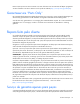
Rear panel components For this server model, PCI expansion slots 1-3 and 6 are reserved.
Item Description Status 1 UID button/LED Blue = Activated Flashing = System is being managed remotely. Off = Deactivated 2 NIC/iLO 2 link Green or flashing green = Activity exists. Off = No activity exists. 3 NIC/iLO 2 activity Green = Link exists. Off = No link exists. PCI expansion slot definitions For this server model, PCI expansion slots 1-3 and 6 are reserved. Slot Type Length Connector Interconnect 4 PCI Express Full x16 x16 4 Optional PCI-X Full 133 MHz/3.
Item Description 8 System battery 9 TPM connector 10 DIMM slots 1-9 11 Reserved 12 System power connector 13 Fan 1 connector 14 Fan 2 connector 15 Processor socket 16 Fan 3 connector 17 Fan 4 connector 18 Fan 5 connector* 19 Power connector 20 Front USB connector 21 Hard drive backplane connector 22 USB tape drive connector 23 Redundant power supply connector 24 Front panel connector 25 Fan 7 connector 26 SATA connectors 1-4 (hard drives) 27 Hard drive backplane conn
Position Default Function S8 Off Reserved * "On" activates the function. NMI functionality An NMI crash dump enables administrators to create crash dump files when a system is hung and not responding to traditional debug mechanisms. Crash dump log analysis is an essential part of diagnosing reliability problems, such as hangs in operating systems, device drivers, and applications. Many crashes freeze a system, and the only available action for administrators is to cycle the system power.
Item Description Definition 1 Size — 2 Rank 1R = Single-rank 2R = Dual-rank 4R = Quad-rank 3 Data width x4 = 4-bit x8 = 8-bit 4 Voltage rating L = Low voltage (1.35v) Blank or omitted = Standard 5 Memory speed 10600 = 1333-MHz 8500 = 1066-MHz 6 DIMM type R = RDIMM (registered) E = UDIMM (unbuffered with ECC) For the latest supported memory information, see the QuickSpecs on the HP website (http://www.hp.com).
Item LED description Status 6 DIMM failure (1-9) Amber = DIMM has failed or is missing. Off = Normal 7 Fan 3 failure Amber = Fan has failed or is missing. Off = Normal 8 Fan 4 failure Amber = Fan has failed or is missing. Off = Normal 9 Fan 5 failure* Amber = Fan has failed or is missing. Off = Normal 10 Fan 7 failure Amber = Fan has failed or is missing. Off = Normal 11 Processor failure Amber = Processor has failed.
FBWC module LEDs The FBWC module has two single-color LEDs (green and amber). The LEDs are duplicated on the reverse side of the cache module to facilitate status viewing. Green LED Amber LED Interpretation Off On A backup is in progress. Flashing (1 Hz) On A restore is in progress. Flashing (1 Hz) Off The capacitor pack is charging. On Off The capacitor pack has completed charging.
Cabling Cabling overview This section provides guidelines that help you make informed decisions about cabling the server and hardware options to optimize performance. Non-redundant power supply cabling CAUTION: When routing cables, always be sure that the cables are not in a position where they can be pinched or air flow can be blocked. IMPORTANT: Route the cables without blocking the airflow or other installed components. Use the cable clips installed in the chassis to manage cable routing.
Optional redundant power supply cabling CAUTION: When routing cables, always be sure that the cables are not in a position where they can be pinched or air flow can be blocked. IMPORTANT: Route the cables without blocking the airflow or other installed components. Use the cable clips installed in the chassis to manage cable routing.
IMPORTANT: Route the cables without blocking the airflow or other installed components. Use the cable clips installed in the chassis to manage cable routing. SATA cabling CAUTION: When routing cables, always be sure that the cables are not in a position where they can be pinched or air flow can be blocked. IMPORTANT: Route the cables without blocking the airflow or other installed components. Use the cable clips installed in the chassis to manage cable routing.
CAUTION: When routing cables, always be sure that the cables are not in a position where they can be pinched or air flow can be blocked. IMPORTANT: Route the cables without blocking the airflow or other installed components. Use the cable clips installed in the chassis to manage cable routing.
Specifications Environmental specifications Specification Value Temperature Operating1 10°C to 35°C (50°F to 90°F) Non-operating 30°C to 60°C (-22°F to 140°F) Maximum rate of temperature change Operating 10°C/hr (18°F/hr) 2,3 20°C/hr (36°F/hr) Non-operating Relative humidity (noncondensing) Operating 10% to 90% Non-operating 5% to 95% Maximum wet bulb temperature (non-condensing) Operating 28°C (82.4°F) Non-operating 38.7°C (101.
Specification Value 13.60 kg (29.98 lb) Weight (maximum configuration: all hard drives, power supplies, and processors installed) 11.60 kg (25.
Maximum peak power • 340 W at 100V to 120V AC input 340 W at 200V to 240V AC input HP ProLiant 460 W Power Supply Specification Value Input requirements Rated input voltage 100 to 120 VAC, 200 to 240 VAC Rated input frequency 50 Hz to 60 Hz Rated input current 5.5 A at 100 VAC 2.
Acronyms and abbreviations ADU Array Diagnostics Utility BBWC battery-backed write cache CSR Customer Self Repair DDR double data rate FBWC flash-backed write cache iLO Integrated Lights-Out IML Integrated Management Log LFF large form-factor MDL midline NCQ native command queuing NMI non-maskable interrupt NVRAM non-volatile memory Acronyms and abbreviations 87
PCIe peripheral component interconnect express PCI-X peripheral component interconnect extended POST Power-On Self Test RBSU ROM-Based Setup Utility RDIMM Registered Dual In-line Memory Module SAS serial attached SCSI SATA serial ATA SFF small form-factor SSD solid-state drive TPM trusted platform module UDIMM Unregistered Dual In-Line Memory Module UID unit identification USB universal serial bus Acronyms and abbreviations 88
Index 9 9.
M mechanical components 16 mechanical specifications 84 memory 49, 76 memory dump 76 N NMI jumper 74, 76 non-hot-plug power supply 34 O operating system crash 76 optical drive 38 optical drive, 9.