HP ProLiant DL320 G6 Server User Guide Part Number 530514-002 March 2010 (Second Edition)
© Copyright 2009, 2010 Hewlett-Packard Development Company, L.P. The information contained herein is subject to change without notice. The only warranties for HP products and services are set forth in the express warranty statements accompanying such products and services. Nothing herein should be construed as constituting an additional warranty. HP shall not be liable for technical or editorial errors or omissions contained herein. Microsoft, Windows, and Windows Server are U.S.
Contents Component identification ............................................................................................................... 7 Front panel components ................................................................................................................................ 7 Front panel LEDs and buttons ......................................................................................................................... 8 SAS and SATA device numbers .............................
Redundant hot-plug power supply option ...................................................................................................... 32 Hard drive options ..................................................................................................................................... 32 Hard drive guidelines ....................................................................................................................... 32 Removing a hard drive blank ......................................
HP Insight Server Migration software for ProLiant ........................................................................................... 61 Keeping the system current .......................................................................................................................... 61 Drivers ............................................................................................................................................ 61 ProLiant Support Packs .......................................
Mechanical specifications ........................................................................................................................... 88 Power supply specifications ......................................................................................................................... 89 Technical support ........................................................................................................................ 92 Before you contact HP .........................................
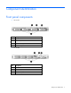
Component identification Front panel components • LFF models Item Description 1 Optical drive blank 2 Serial label pull tab 3 USB connectors (2) 4 Hard drive bays • SFF models Item Description 1 Optical drive blank 2 Serial label pull tab 3 USB connectors (2) 4 Hard drive bays Component identification 7
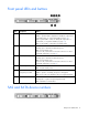
Front panel LEDs and buttons Item Description Status 1 Internal health LED Green = System health is normal. Amber = System health is degraded. To identify the component in a degraded state, see "System board LEDs (on page 13)." Red = System health is critical. To identify the component in a critical state, see "System board LEDs (on page 13)." Off = System health is normal (when in standby mode). 2 NIC 1 link/activity LED Green = Network link exists.
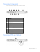
Rear panel components For this server model, PCI expansion slots 1-3 and 6 are reserved.
Item Description Status 1 UID button/LED Blue = Activated Flashing = System is being managed remotely. Off = Deactivated 2 NIC/iLO 2 link Green or flashing green = Activity exists. Off = No activity exists. 3 NIC/iLO 2 activity Green = Link exists. Off = No link exists. PCI expansion slot definitions For this server model, PCI expansion slots 1-3 and 6 are reserved. Slot Type Length Connector Interconnect 4 PCI Express Full x16 x16 4 Optional PCI-X Full 133 MHz/3.
Item Description 6 Dedicated iLO 2 module connector (optional) 7 NMI jumper 8 System battery 9 TPM connector 10 DIMM slots 1-9 11 Reserved 12 System power connector 13 Fan 1 connector 14 Fan 2 connector 15 Processor socket 16 Fan 3 connector 17 Fan 4 connector 18 Fan 5 connector* 19 Power connector 20 Front USB connector 21 Hard drive backplane connector 22 USB tape drive connector 23 Redundant power supply connector 24 Front panel connector 25 Fan 7 connector 26 S
Position Default Function S6 Off Off = Normal operation On = BIOS will clear CMOS and NVRAM* S7 Off Reserved S8 Off Reserved * "On" activates the function. NMI functionality An NMI crash dump enables administrators to create crash dump files when a system is hung and not responding to traditional debug mechanisms. Crash dump log analysis is an essential part of diagnosing reliability problems, such as hangs in operating systems, device drivers, and applications.
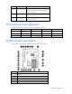
System board LEDs Item LED description Status 1 Fan 6 failure (reserved) — 2 Power supply Off = No AC power or failed power supply Green = Power supply is on and functioning. 3 Overtemperature Amber = System has reached a cautionary or critical temperature level. Off = Normal 4 Fan 1 failure Amber = Fan has failed or is missing. Off = Normal 5 Fan 2 failure Amber = Fan has failed or is missing. Off = Normal 6 DIMM failure (1-9) Amber = DIMM has failed or is missing.
System LEDs and internal health LED combinations When the internal health LED on the front panel illuminates either amber or red, the server is experiencing a health event. Combinations of illuminated system LEDs and the internal health LED indicate system status. The front panel health LEDs indicate only the current hardware status. In some situations, HP SIM may report server status differently than the health LEDs because the software tracks more system attributes.
Fan 6 is reserved.
Operations Power up the server To power up the server, press the Power On/Standby button. Power down the server WARNING: To reduce the risk of personal injury, electric shock, or damage to the equipment, remove the power cord to remove power from the server. The front panel Power On/Standby button does not completely shut off system power. Portions of the power supply and some internal circuitry remain active until AC power is removed.
5. Place the server on a sturdy, level surface. Remove the access panel WARNING: To reduce the risk of personal injury from hot surfaces, allow the drives and the internal system components to cool before touching them. CAUTION: Do not operate the server for long periods with the access panel open or removed. Operating the server in this manner results in improper airflow and improper cooling that can lead to thermal damage. To remove the component: 1. Power down the server (on page 16). 2.
CAUTION: To prevent damage to the server or expansion boards, power down the server and remove all AC power cords before removing or installing the PCI riser board assembly. 1. Power down the server (on page 16). 2. Remove the server from the rack (on page 16). 3. Remove the access panel (on page 17). 4. Disconnect all internal cables connected to existing expansion boards. 5. Remove the PCI riser board assembly: a. Remove the T-10 screw. b. Remove the T-15 screws. c.
1. Install the PCI riser board assembly. 2. Connect any internal cables for expansion boards. 3. Install the access panel. 4. Install the server into the rack.
Setup Optional installation services Delivered by experienced, certified engineers, HP Care Pack services help you keep your servers up and running with support packages tailored specifically for HP ProLiant systems. HP Care Packs let you integrate both hardware and software support into a single package. A number of service level options are available to meet your needs.
Optimum environment When installing the server in a rack, select a location that meets the environmental standards described in this section. Space and airflow requirements To allow for servicing and adequate airflow, observe the following space and airflow requirements when deciding where to install a rack: • Leave a minimum clearance of 63.5 cm (25 in) in front of the rack. • Leave a minimum clearance of 76.2 cm (30 in) behind the rack. • Leave a minimum clearance of 121.
The maximum recommended ambient operating temperature (TMRA) for most server products is 35°C (95°F). The temperature in the room where the rack is located must not exceed 35°C (95°F). CAUTION: To reduce the risk of damage to the equipment when installing third-party options: • Do not permit optional equipment to impede airflow around the server or to increase the internal rack temperature beyond the maximum allowable limits. • Do not exceed the manufacturer’s TMRA.
Rack warnings WARNING: To reduce the risk of personal injury or damage to the equipment, be sure that: • The leveling jacks are extended to the floor. • The full weight of the rack rests on the leveling jacks. • The stabilizing feet are attached to the rack if it is a single-rack installation. • The racks are coupled together in multiple-rack installations. • Only one component is extended at a time. A rack may become unstable if more than one component is extended for any reason.
Installing the server into the rack To install the server into a rack with square, round, or threaded holes, refer to the instructions that ship with the rack hardware kit. If you are installing the server into a telco rack, order the appropriate option kit at the RackSolutions.com website (http://www.racksolutions.com/hp). Follow the server-specific instructions on the website to install the rack brackets. Use the following information when connecting peripheral cables and power cords to the server.
Installing the operating system To operate properly, the server must have a supported OS. For the latest information on OS support, refer to the HP website (http://www.hp.com/go/supportos). Two methods are available to install an OS on the server: • SmartStart assisted installation—Insert the SmartStart CD into the CD-ROM drive and reboot the server. • Manual installation—Insert the OS CD into the CD-ROM drive and reboot the server.
Hardware options installation Introduction If more than one option is being installed, read the installation instructions for all the hardware options and identify similar steps to streamline the installation process. WARNING: To reduce the risk of personal injury from hot surfaces, allow the drives and the internal system components to cool before touching them. CAUTION: To prevent damage to electrical components, properly ground the server before beginning any installation procedure.
Channel Slot Slot number 3 I 7 F 8 C 9 This multi-channel architecture provides enhanced performance in Advanced ECC mode. This architecture also enables the Mirrored Memory and Lockstep memory modes. This server supports both Registered PC3 DIMMSs (RDIMMs) and Unbuffered DIMMs (UDIMMs). DIMM slots in this server are identified by number and by letter. Letters identify the slots to populate for specific AMP modes. Slot numbers are reported by ROM messages during boot and for error reporting.
The memory subsystem may be populated with either RDIMMs or UDIMMs, but mixing the two types is not supported. To determine DIMM characteristics, use the label attached to the DIMM and the following illustration and table.
Advanced Memory Protection options are configured in RBSU. If the requested AMP mode is not supported by the installed DIMM configuration, the server boots in Advanced ECC mode. For more information, see "HP ROM-Based Setup Utility (on page 53)." For the latest memory configuration information, see the QuickSpecs on the HP website (http://www.hp.com). RDIMM maximum memory configurations The following table lists the maximum memory configuration possible with 8-GB RDIMMs.
• Each channel supports up to two Unbuffered DIMMs. • If quad-rank DIMMs are installed for a processor, a maximum of two DIMMs can be installed on each channel for that processor. • If a channel contains quad-rank DIMMs, the quad-rank DIMM must be installed first on that channel. DIMM speeds are supported as indicated in the following table.
• o Last: G and H o Do not populate slots C, F, or I. UDIMM o First: A and B o Last: D and E o Do not populate slots C, F, G, H, or I. After installing the DIMMs, use RBSU to configure the system for Lockstep memory support ("Configuring lockstep memory" on page 55). Installing a DIMM CAUTION: To avoid damage to the hard drives, memory, and other system components, the air baffle, drive blanks, and access panel must be installed when the server is powered up. 1.
Redundant hot-plug power supply option To install the component: 1. Remove the power supply blank. 2. Install the power supply. 3. Connect the power cord to the power supply. 4. Connect the power cord to the AC power source. Hard drive options The server provides non-hot-plug capability through an embedded SATA controller. To obtain hot-plug capability, install an optional controller and hot-plug cable option kit.
• Drives must be the same capacity to provide the greatest storage space efficiency when drives are grouped together into the same drive array. Optional storage controllers provide support for hot-plug capability and drive LEDs. Controller options are: • The embedded controller supports non-hot-plug SATA hard drives. Drive LEDs are not supported. • Optional SATA controllers support hot-plug SATA hard drives and drive LEDs.
3. Remove the hard drive. Installing a hard drive IMPORTANT: Hot-plug capability and drive LED support are only available when a supported optional controller is installed in the server. 1. Power down the server (on page 16). 2. Remove the existing hard drive blank ("Removing a hard drive blank" on page 33). 3. Prepare the hard drive.
4. Install the hard drive. Optical drive option To install the component: 1. Power down the server (on page 16). 2. Remove the server from the rack (on page 16). 3. Remove the access panel (on page 17). 4. Remove the air baffle (on page 17). 5. Remove the 9.5-mm optical drive blank. Retain the blank for future use.
6. Install the 9.5-mm optical drive assembly. When fully inserted, the assembly locking latch clicks. 7. Using a T-15 screwdriver, secure the drive to the chassis. 8. Connect the optical drive and power cable to the optical drive.
9. Route the cable, and then connect the SATA connector to the system board. 10. Connect the power connector to the power supply backplane. 11. Install the access panel. 12. Install the server into the rack. Dedicated iLO 2 port module option To install the component: 1. Power down the server (on page 16). 2. Remove the server from the rack (on page 16). 3. Remove the access panel (on page 17). 4. Press inward on the knockout. 5. Twist and pull to remove the knockout from the chassis.
6. Using a T-15 Torx screwdriver, install the dedicated iLO 2 management port module. 7. Install the access panel. 8. Install the server into the rack. Expansion board option To install the component: 1. Power down the server (on page 16). 2. Remove the server from the rack (on page 16). 3. Remove the access panel (on page 17). 4. Disconnect all internal cables connected to any existing expansion boards. 5. Remove the PCI riser board assembly (on page 17). 6.
7. Install the expansion board. IMPORTANT: The server does not power up if the PCI riser board assembly is not seated properly. 8. Install the PCI riser board assembly (on page 18). 9. Connect all internal cables for expansion boards. 10. Install the access panel. 11. Install the server into the rack. PCI-X riser board option To install the component: 1. Power down the server (on page 16). 2. Remove the server from the rack (on page 16). 3. Remove the access panel (on page 17). 4.
7. Remove the PCIe riser board from the assembly. 8. Install the optional PCI-X riser board. 9. Install a PCI-X expansion board ("Expansion board option" on page 38). IMPORTANT: The server does not power up if the PCI riser board assembly is not seated properly. 10. Install the PCI riser board assembly (on page 18). 11. Connect all internal cables for expansion boards. 12. Install the access panel. 13. Install the server into the rack.
IMPORTANT: The server does not power up if the PCI riser board assembly is not seated properly. 8. Install the PCI riser board assembly (on page 18). 9. Connect the mini-SAS to mini-SAS cable, provided in the mini-SAS to mini-SAS cable option kit, to the hard drive backplane and to the storage controller. For more information, see "Optional SAS controller cabling (on page 50)." 10. Install the access panel. 11. Install the server into the rack.
7. Install the cache module. 8. Install the storage controller, if not installed ("Storage controller option" on page 40). 9. Install the capacitor pack. 10. Route the cable. ("BBWC battery pack or FBWC capacitor pack cabling to an optional controller" on page 51) 11. Install the access panel. 12. Install the server into the rack. 13. Power up the server (on page 16).
CAUTION: After the server is powered down, wait 15 seconds and then check the amber LED before unplugging the cable from the cache module. If the amber LED blinks after 15 seconds, do not remove the cable from the cache module. The cache module is backing up data, and data is lost if the cable is detached. IMPORTANT: The battery pack might have a low charge when installed. In this case, a POST error message is displayed when the server is powered up, indicating that the battery pack is temporarily disabled.
6. Connect the cable to the cache module. 7. Install the battery pack. 8. Route the cable ("BBWC battery pack or FBWC capacitor pack cabling to an optional controller" on page 51). 9. Install the access panel. 10. Install the server into the rack. HP Trusted Platform Module option Use these instructions to install and enable a TPM on a supported server. This procedure includes three sections: 1. Installing the Trusted Platform Module board. 2. Retaining the recovery key/password (on page 46).
Enabling the TPM requires accessing the ROM-Based Setup Utility (RBSU) ("HP ROM-Based Setup Utility" on page 53). For more information about RBSU, see the HP website (http://www.hp.com/support/smartstart/documentation). TPM installation requires the use of drive encryption technology, such as the Microsoft® Windows® BitLocker™ Drive Encryption feature. For more information on BitLocker™, see the Microsoft website (http://www.microsoft.com). CAUTION: Always observe the guidelines in this document.
5. Install the TPM board. Press down on the connector to seat the board. 6. Install the TPM security rivet by pressing the rivet firmly into the system board. 7. Install the access panel. 8. Install the server into the rack. 9. Power up the server (on page 16). Retaining the recovery key/password The recovery key/password is generated during BitLocker™ setup, and can be saved and printed after BitLocker™ is enabled. When using BitLocker™, always retain the recovery key/password.
• Do not save the recovery key/password on the encrypted hard drive. Enabling the Trusted Platform Module 1. When prompted during the start-up sequence, access RBSU by pressing the F9 key. 2. From the Main Menu, select Server Security. 3. From the Server Security Menu, select Trusted Platform Module. 4. From the Trusted Platform Module Menu, select TPM Functionality. 5. Select Enable, and then press the Enter key to modify the TPM Functionality setting. 6.
Cabling Cabling overview This section provides guidelines that help you make informed decisions about cabling the server and hardware options to optimize performance. Non-redundant power supply cabling CAUTION: When routing cables, always be sure that the cables are not in a position where they can be pinched or air flow can be blocked. IMPORTANT: Route the cables without blocking the airflow or other installed components. Use the cable clips installed in the chassis to manage cable routing.
Optional redundant power supply cabling CAUTION: When routing cables, always be sure that the cables are not in a position where they can be pinched or air flow can be blocked. IMPORTANT: Route the cables without blocking the airflow or other installed components. Use the cable clips installed in the chassis to manage cable routing.
IMPORTANT: Route the cables without blocking the airflow or other installed components. Use the cable clips installed in the chassis to manage cable routing. SATA cabling CAUTION: When routing cables, always be sure that the cables are not in a position where they can be pinched or air flow can be blocked. IMPORTANT: Route the cables without blocking the airflow or other installed components. Use the cable clips installed in the chassis to manage cable routing.
CAUTION: When routing cables, always be sure that the cables are not in a position where they can be pinched or air flow can be blocked.
Configuration and utilities Configuration tools SmartStart software SmartStart is a collection of software that optimizes single-server setup, providing a simple and consistent way to deploy server configuration. SmartStart has been tested on many ProLiant server products, resulting in proven, reliable configurations.
variables to determine the configuration and then writes the results to an editable script file. This file can then be deployed across multiple servers with similar hardware and software components. For more information, refer to the SmartStart Scripting Toolkit User Guide on the HP website (http://h18004.www1.hp.com/products/servers/management/toolkit/documentation.html).
NOTE: If the boot drive is not empty or has been written to in the past, ORCA does not automatically configure the array. You must run ORCA to configure the array settings. Drives installed Drives used RAID level 1 1 RAID 0 2 2 RAID 1 3, 4, 5, or 6 3, 4, 5, or 6 RAID 5 More than 6 0 None To change any ORCA default settings and override the auto-configuration process, press the F8 key when prompted. By default, the auto-configuration process configures the system for the English language.
7. Press the Esc key to exit the current menu or press the F10 key to exit RBSU. For more information on mirrored memory, see the white paper on the HP website (http://h18000.www1.hp.com/products/servers/technology/memoryprotection.html). Configuring lockstep memory To configure Lockstep memory: 1. Install the required DIMMs ("Installing a DIMM" on page 31). 2. Access RBSU by pressing the F9 key during power-up when the prompt is displayed. 3. Select System Options. 4.
• Setting the controller to be the boot controller If you do not use the utility, ORCA will default to the standard configuration. For more information regarding array controller configuration, refer to the controller user guide. For more information regarding the default configurations that ORCA uses, refer to the HP ROM-Based Setup Utility User Guide on the Documentation CD. HP ProLiant Essentials Rapid Deployment Pack The RDP software is the preferred method for rapid, high-volume server deployments.
ASR increases server availability by restarting the server within a specified time after a system hang or shutdown. At the same time, the HP SIM console notifies you by sending a message to a designated pager number that ASR has restarted the system. You can disable ASR from the HP SIM console or through RBSU. ROMPaq utility The ROMPaq utility enables you to upgrade the system firmware (BIOS).
StorageWorks library and tape tools HP StorageWorks L&TT provides functionality for firmware downloads, verification of device operation, maintenance procedures, failure analysis, corrective service actions, and some utility functions. It also provides seamless integration with HP hardware support by generating and emailing support tickets that deliver a snapshot of the storage system. For more information, and to download the utility, refer to the StorageWorks L&TT website (http://h18006.www1.hp.
USB support HP provides both standard USB support and legacy USB support. Standard support is provided by the OS through the appropriate USB device drivers. Before the OS loads, HP provides support for USB devices through legacy USB support, which is enabled by default in the system ROM. Legacy USB support provides USB functionality in environments where USB support is not available normally.
HP Insight Diagnostics survey functionality HP Insight Diagnostics (on page 59) provides survey functionality that gathers critical hardware and software information on ProLiant servers. This functionality supports operating systems that may not be supported by the server. For operating systems supported by the server, see the HP website (http://www.hp.com/go/supportos).
• For small and midsize environments: HP Insight Remote Support Standard provides basic remote monitoring, notification/advisories and service dispatch. It is optimized for environments with 1 to 50 servers and can be installed on a shared HP ProLiant Windows application server. The software supports HP EVA storage devices, HP ProLiant, BladeSystems, HP Integrity and HP 9000 servers running Microsoft Windows, Red Hat Enterprise Linux, Novell SUSE and Novell Netware.
If you do not use the SmartStart CD to install an operating system, drivers for some of the new hardware are required. These drivers, as well as other option drivers, ROM images, and value-add software can be downloaded from the HP website (http://www.hp.com/support). IMPORTANT: Always perform a backup before installing or updating device drivers. ProLiant Support Packs PSPs represent operating system-specific bundles of ProLiant optimized drivers, utilities, and management agents.
Troubleshooting Troubleshooting resources The HP ProLiant Servers Troubleshooting Guide provides procedures for resolving common problems and comprehensive courses of action for fault isolation and identification, error message interpretation, issue resolution, and software maintenance on ProLiant servers and server blades. This guide includes problemspecific flowcharts to help you navigate complex troubleshooting processes. To view the guide, select a language: • English (http://www.hp.
Symbols on equipment The following symbols may be placed on equipment to indicate the presence of potentially hazardous conditions. This symbol indicates the presence of hazardous energy circuits or electric shock hazards. Refer all servicing to qualified personnel. WARNING: To reduce the risk of injury from electric shock hazards, do not open this enclosure. Refer all maintenance, upgrades, and servicing to qualified personnel. This symbol indicates the presence of electric shock hazards.
WARNING: To reduce the risk of electric shock or damage to the equipment: • Do not disable the power cord grounding plug. The grounding plug is an important safety feature. • Plug the power cord into a grounded (earthed) electrical outlet that is easily accessible at all times. • Unplug the power cord from the power supply to disconnect power to the equipment. • Do not route the power cord where it can be walked on or pinched by items placed against it.
Prepare the server for diagnosis 1. Be sure the server is in the proper operating environment with adequate power, air conditioning, and humidity control. For required environmental conditions, see the server documentation. 2. Record any error messages displayed by the system. 3. Remove all diskettes, CD-ROMs, DVD-ROMs, and USB drive keys. 4. Power down the server and peripheral devices if you will be diagnosing the server offline. If possible, always perform an orderly shutdown: a.
Service notifications To view the latest service notifications, refer to the HP website (http://www.hp.com/go/bizsupport). Select the appropriate server model, and then click the Troubleshoot a Problem link on the product page. Troubleshooting flowcharts To effectively troubleshoot a problem, HP recommends that you start with the first flowchart in this section, "Start diagnosis flowchart (on page 67)," and follow the appropriate diagnostic path.
General diagnosis flowchart The General diagnosis flowchart provides a generic approach to troubleshooting. If you are unsure of the problem, or if the other flowcharts do not fix the problem, use the following flowchart. Item Refer to 1 "Symptom information (on page 65)" 2 "Loose connections (on page 66)" 3 "Service notifications (on page 67)" 4 The most recent version of a particular server or option firmware is available on the HP Support website (http://www.hp.com/support).
Item Refer to 5 "General memory problems are occurring" in the HP ProLiant Servers Troubleshooting Guide located on the Documentation CD or on the HP website (http://www.hp.com/support) 6 Server maintenance and service guide, located on the Documentation CD or the HP website (http://www.hp.com/products/servers/platforms) 7 • Server maintenance and service guide, located on the Documentation CD or the HP website (http://www.hp.
Server power-on problems flowchart Symptoms: • The server does not power on. • The system power LED is off or amber.
• The external health LED is red or amber. • The internal health LED is red or amber. NOTE: For the location of server LEDs and information on their statuses, refer to the server documentation.
Troubleshooting 72
POST problems flowchart Symptoms: • Server does not complete POST NOTE: The server has completed POST when the system attempts to access the boot device.
Item Refer to OS boot problems flowchart Symptoms: • Server does not boot a previously installed operating system Troubleshooting 74
• Server does not boot SmartStart Possible causes: • Corrupted operating system • Hard drive subsystem problem • Incorrect boot order setting in RBSU Item Refer to 1 HP ROM-Based Setup Utility User Guide (http://www.hp.com/servers/smartstart) 2 "POST problems flowchart (on page 73)" 3 • "Hard drive problems" in the HP ProLiant Servers Troubleshooting Guide located on the Documentation CD or on the HP website (http://www.hp.
Server fault indications flowchart Symptoms: • Server boots, but a fault event is reported by Insight Management Agents (on page 58) • Server boots, but the internal health LED, external health LED, or component health LED is red or amber Troubleshooting 76
NOTE: For the location of server LEDs and information on their statuses, refer to the server documentation. Possible causes: • Improperly seated or faulty internal or external component • Unsupported component installed • Redundancy failure • System overtemperature condition Item Refer to 1 "Management agents (on page 58)" or in the HP ProLiant Servers Troubleshooting Guide located on the Documentation CD or on the HP website (http://www.hp.
POST error messages and beep codes For a complete listing of error messages, refer to the "POST error messages" in the HP ProLiant Servers Troubleshooting Guide located on the Documentation CD or on the HP website (http://www.hp.com/support). WARNING: To avoid potential problems, ALWAYS read the warnings and cautionary information in the server documentation before removing, replacing, reseating, or modifying system components.
Battery replacement If the server no longer automatically displays the correct date and time, you may need to replace the battery that provides power to the real-time clock. Under normal use, battery life is 5 to 10 years. WARNING: The computer contains an internal lithium manganese dioxide, a vanadium pentoxide, or an alkaline battery pack. A risk of fire and burns exists if the battery pack is not properly handled. To reduce the risk of personal injury: • Do not attempt to recharge the battery.
For more information about battery replacement or proper disposal, contact an authorized reseller or an authorized service provider.
Regulatory compliance notices Regulatory compliance identification numbers For the purpose of regulatory compliance certifications and identification, this product has been assigned a unique regulatory model number. The regulatory model number can be found on the product nameplate label, along with all required approval markings and information. When requesting compliance information for this product, always refer to this regulatory model number.
to radio communications. However, there is no guarantee that interference will not occur in a particular installation. If this equipment does cause harmful interference to radio or television reception, which can be determined by turning the equipment off and on, the user is encouraged to try to correct the interference by one or more of the following measures: • Reorient or relocate the receiving antenna. • Increase the separation between the equipment and receiver.
Canadian notice (Avis Canadien) Class A equipment This Class A digital apparatus meets all requirements of the Canadian Interference-Causing Equipment Regulations. Cet appareil numérique de la classe A respecte toutes les exigences du Règlement sur le matériel brouilleur du Canada. Class B equipment This Class B digital apparatus meets all requirements of the Canadian Interference-Causing Equipment Regulations.
This symbol on the product or on its packaging indicates that this product must not be disposed of with your other household waste. Instead, it is your responsibility to dispose of your waste equipment by handing it over to a designated collection point for the recycling of waste electrical and electronic equipment.
Korean notice Class A equipment Class B equipment Chinese notice Class A equipment Laser compliance This product may be provided with an optical storage device (that is, CD or DVD drive) and/or fiber optic transceiver. Each of these devices contains a laser that is classified as a Class 1 Laser Product in accordance with US FDA regulations and the IEC 60825-1. The product does not emit hazardous laser radiation. Each laser product complies with 21 CFR 1040.10 and 1040.
WARNING: The computer contains an internal lithium manganese dioxide, a vanadium pentoxide, or an alkaline battery pack. A risk of fire and burns exists if the battery pack is not properly handled. To reduce the risk of personal injury: • Do not attempt to recharge the battery. • Do not expose the battery to temperatures higher than 60°C (140°F). • Do not disassemble, crush, puncture, short external contacts, or dispose of in fire or water.
Electrostatic discharge Preventing electrostatic discharge To prevent damaging the system, be aware of the precautions you need to follow when setting up the system or handling parts. A discharge of static electricity from a finger or other conductor may damage system boards or other static-sensitive devices. This type of damage may reduce the life expectancy of the device. To prevent electrostatic damage: • Avoid hand contact by transporting and storing products in static-safe containers.
Specifications Environmental specifications Specification Value Temperature Operating1 10°C to 35°C (50°F to 90°F) Non-operating 30°C to 60°C (-22°F to 140°F) Maximum rate of temperature change Operating 2,3 Non-operating 10°C/hr (18°F/hr) 20°C/hr (36°F/hr) Relative humidity (noncondensing) Operating 10% to 90% Non-operating 5% to 95% Maximum wet bulb temperature (non-condensing) Operating 28°C (82.4°F) Non-operating 38.7°C (101.
Specification Value Weight (maximum configuration: all hard drives, power supplies, and processors installed) 13.60 kg (29.98 lb) Weight (minimum configuration: one hard drive, power supply, and processor installed) 11.60 kg (25.
Rated input power 450 W at 100V AC input 420 W at 200V AC input BTUs per hour 1708 at 100V AC input 1640 at 200V AC input Power supply output Rated steady-state power 340 W at 100V to 120V AC input 340 W at 200V to 240V AC input Maximum peak power 340 W at 100V to 120V AC input 340 W at 200V to 240V AC input • HP ProLiant 460 W Power Supply Specification Value Input requirements Rated input voltage 100 to 120 VAC, 200 to 240 VAC Rated input frequency 50 Hz to 60 Hz Rated input current 5.
Rated input power 575 W at 100V AC input 575 W at 200V AC input BTUs per hour 1962 at 120V AC input 1962 at 200V to 240V AC input Power supply output Rated steady-state power 500 W at 100V to 120V AC input 500 W at 200V to 240V AC input Maximum peak power 500 W at 100V to 120V AC input 500 W at 200V to 240V AC input Specifications 91
Technical support Before you contact HP Be sure to have the following information available before you call HP: • Technical support registration number (if applicable) • Product serial number • Product model name and number • Product identification number • Applicable error messages • Add-on boards or hardware • Third-party hardware or software • Operating system type and revision level HP contact information For the name of the nearest HP authorized reseller: • See the Contact HP worldwi
• Optional—Parts for which customer self repair is optional. These parts are also designed for customer self repair. If, however, you require that HP replace them for you, there may or may not be additional charges, depending on the type of warranty service designated for your product. NOTE: Some HP parts are not designed for customer self repair. In order to satisfy the customer warranty, HP requires that an authorized service provider replace the part.
Pour plus d'informations sur le programme CSR de HP, contactez votre Mainteneur Agrée local. Pour plus d'informations sur ce programme en Amérique du Nord, consultez le site Web HP (http://www.hp.com/go/selfrepair). Riparazione da parte del cliente Per abbreviare i tempi di riparazione e garantire una maggiore flessibilità nella sostituzione di parti difettose, i prodotti HP sono realizzati con numerosi componenti che possono essere riparati direttamente dal cliente (CSR, Customer Self Repair).
HINWEIS: Einige Teile sind nicht für Customer Self Repair ausgelegt. Um den Garantieanspruch des Kunden zu erfüllen, muss das Teil von einem HP Servicepartner ersetzt werden. Im illustrierten Teilekatalog sind diese Teile mit „No“ bzw. „Nein“ gekennzeichnet. CSR-Teile werden abhängig von der Verfügbarkeit und vom Lieferziel am folgenden Geschäftstag geliefert. Für bestimmte Standorte ist eine Lieferung am selben Tag oder innerhalb von vier Stunden gegen einen Aufpreis verfügbar.
el caso de todas sustituciones que lleve a cabo el cliente, HP se hará cargo de todos los gastos de envío y devolución de componentes y escogerá la empresa de transporte que se utilice para dicho servicio. Para obtener más información acerca del programa de Reparaciones del propio cliente de HP, póngase en contacto con su proveedor de servicios local. Si está interesado en el programa para Norteamérica, visite la página web de HP siguiente (http://www.hp.com/go/selfrepair).
Opcional – Peças cujo reparo feito pelo cliente é opcional. Essas peças também são projetadas para o reparo feito pelo cliente. No entanto, se desejar que a HP as substitua, pode haver ou não a cobrança de taxa adicional, dependendo do tipo de serviço de garantia destinado ao produto. OBSERVAÇÃO: Algumas peças da HP não são projetadas para o reparo feito pelo cliente. A fim de cumprir a garantia do cliente, a HP exige que um técnico autorizado substitua a peça.
Technical support 98
Technical support 99
Acronyms and abbreviations ABEND abnormal end ACU Array Configuration Utility ASR Automatic Server Recovery DDR double data rate IEC International Electrotechnical Commission iLO Integrated Lights-Out IML Integrated Management Log KVM keyboard, video, and mouse NMI non-maskable interrupt NVRAM non-volatile memory ORCA Option ROM Configuration for Arrays PCI Express Peripheral Component Interconnect Express Acronyms and abbreviations 100
PCI-X peripheral component interconnect extended PDU power distribution unit POST Power-On Self Test PSP ProLiant Support Pack RBSU ROM-Based Setup Utility RDP Rapid Deployment Pack SAS serial attached SCSI SATA serial ATA SIM Systems Insight Manager UID unit identification USB universal serial bus VCA Version Control Agent Acronyms and abbreviations 101
Index A access panel 17 activity LED 8 ACU (Array Configuration Utility) 55 additional information 63 ADU (Array Diagnostic Utility) 60 air baffle 17 airflow requirements 21 Altiris eXpress Deployment Server 56 Array Configuration Utility (ACU) 55 authorized reseller 92 authorized technician 64 auto-configuration process 53 B battery 12, 79, 85 battery-backed write cache (BBWC) 42 battery-backed write cache battery pack 42 battery-backed write cache cabling 51 BIOS Serial Console 54 BIOS upgrade 57 blue sc
F fans 14 FBWC module 41 FCC (Federal Communications Commission) notice 81, 82 FCC rating label 81 features 7 Federal Communications Commission (FCC) notice 81, 82 firmware upgrade utility, troubleshooting 63 front panel buttons 8 front panel components 7 front panel LEDs 8, 14 IML (Integrated Management Log) 60 Important Safety Information document 63 Insight Diagnostics 59, 60, 61 installation services 20 installing operating system 25 installing the Trusted Platform Module board 45 Integrated Lights-Out
optimum environment 21 Option ROM Configuration for Arrays (ORCA) 55 options installation 23, 26 ORCA (Option ROM Configuration for Arrays) 55 OS boot problems flowchart 74 P passwords 46 PCI expansion slot definitions 10 PCI riser board assembly 17, 18, 53, 56, 59, 60, 63 PCI slots 16 PCI-X riser board 39 phone numbers 92 POST error messages 78 POST problems flowchart 73 power cord 64, 86 power distribution unit (PDU) 22 power on LED 8 Power On/Standby button 8, 16, 25 power requirements 22 power supplies
TPM (Trusted Platform Module) 44 troubleshooting 63 troubleshooting flowcharts 67 troubleshooting, firmware upgrade utility 63 Trusted Platform Module (TPM) 44, 46 U UDIMM configuration 29 UID button 8, 9 UID LED 8, 9, 12 updating the system ROM 58 UPS (uninterruptible power supply) 22 USB support 59 utilities 52 V ventilation 21 W warnings 23, 64 website, HP 92 Index 105