ProLiant DL320 Server Maintenance and Service Guide Part Number 203834-003 Spare Part Number 207739-001 January 2002 (Third Edition) COMPAQ CONFIDENTIAL Codename: DarkStar-T Part Number: 203834-003 Last Saved On: 12/20/01 1:38 PM
© 2002 Compaq Information Technologies Group, L.P. Compaq, the Compaq logo, ProLiant, Compaq Insight Manager, ROMPaq, SmartStart, and QuickFind are trademarks of Compaq Information Technologies Group, L.P. in the U.S. and/or other countries. Microsoft, MS-DOS, Windows, and Windows NT are trademarks of Microsoft Corporation in the U.S. and/or other countries. Intel and Pentium are trademarks of Intel Corporation in the U.S. and/or other countries.
Contents About This Guide Symbols in Text.......................................................................................................................................... vii Important Safety Information ..................................................................................................................... vii Compaq Technician Notes..........................................................................................................................
Contents PCI Riser Board Assembly ..................................................................................................................... 2-27 Expansion Board............................................................................................................................... 2-28 PCI Card Guide................................................................................................................................. 2-29 Center Wall .............................................
Contents Compaq NC3163 Fast Ethernet NIC 10/100 Wake On LAN..................................................................
About This Guide This maintenance and service guide is a troubleshooting guide that can be used for reference when servicing Compaq ProLiant DL320 servers. WARNING: To reduce the risk of personal injury from electric shock and hazardous energy levels, only authorized service technicians should attempt to repair this equipment. Improper repairs can create conditions that are hazardous. Symbols in Text These symbols may be found in the text of this guide. They have the following meanings.
About This Guide WARNING: To reduce the risk of personal injury from electric shock and hazardous energy levels, do not exceed the level of repairs specified in these procedures. Because of the complexity of the individual boards and subassemblies, do not attempt to make repairs at the component level or to make modifications to any printed wiring board. Improper repairs can create conditions that are hazardous.
About This Guide Where to Go for Additional Help In addition to this guide, the following information sources are available: • User documentation • Compaq Service Quick Reference Guide • Service training guides • Compaq service advisories and bulletins • Compaq QuickFind™ information services • Compaq Insight Manager software For additional copies, visit the Compaq website: www.compaq.
About This Guide • Monospace typeface is used for command lines, code examples, screen displays, error messages, and user input. • x Sans serif typeface is used for uniform resource locators (URLs).
1 Illustrated Parts Catalog This chapter provides the illustrated parts breakdown for the Compaq ProLiant DL320 server. The corresponding table in this chapter provides names and ordering numbers for all referenced spare parts.
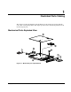
Illustrated Parts Catalog System Components Exploded View 12 3 11 10 28 14 6 8 9 4 4 7 4 4 5 4 6 13 Figure 1-2: System components exploded view System and Mechanical Spare Parts List Table 1-1: System and Mechanical Spare Parts List Item Description Spare Parts List Mechanical Components 1a Chassis 207735-001 1b Access panel 2 Fixed cable tray 173839-001 3 PCI riser board assembly 207727-001 4 Fan 207729-001 5 Center wall and bracket with fans 213288-001 6 Power supply, 180
Illustrated Parts Catalog Table 1-1: System and Mechanical Spare Parts List continued Item Description Spare Parts List Boards 7 User interface board 207725-001 8 CD-ROM(DVD-ROM)/diskette drive assembly backplane 207726-001 9a System board 207723-001 9b System board for 1.
Illustrated Parts Catalog Table 1-1: System and Mechanical Spare Parts List continued Item Description 21 Plastics kit 21a Bezel 21b Shipping/ejector key 21c PCI card guide * 21d Bezel screws * 22 Spare Parts List 207733-001 Hardware kit 207734-001 22a Hard drive tray 22b Bezel blank 22c Cable support bracket 22d PCI slot cover * 22e Vertical-mount PDU bracket * 23 Rack mounting kit (fixed rack rails) * 173845-001 24 Replacement battery, 3-V lithium * 234556-001 25 Return k
2 Removal and Replacement Procedures This chapter provides subassembly and module-level removal and replacement procedures for Compaq ProLiant DL320 servers. After completing all necessary removal and replacement procedures, run the diagnostics program to verify that all components operate properly.
Removal and Replacement Procedures Symbols on Equipment Any surface or area of the equipment marked with these symbols indicates the presence of a hot surface or hot component. WARNING: To reduce the risk of injury from a hot component, allow the surface to cool before touching it. To reduce the risk of injury from electric shock hazards, do not open this enclosure. WARNING: Any surface or area of the equipment marked with these symbols indicates the presence of electric shock hazards.
Removal and Replacement Procedures Server Warnings and Precautions WARNING: To reduce the risk of personal injury from hot surfaces, allow the hot-plug drives and the internal system components to cool before touching them. WARNING: To reduce the risk of electric shock or damage to the equipment: • Do not disable the power cord grounding plug. The grounding plug is an important safety feature. • Plug the power cord into a grounded (earthed) electrical outlet that is easily accessible at all times.
Removal and Replacement Procedures • User interface board • PCI riser board assembly • Expansion board • PCI card guide • Center wall • System fans — Fans 1, 2, and 3 — Fans 4 and 5 • Cables — Two-device terminated SCSI cable — ATA cables — CD-ROM (DVD-ROM)/diskette drive assembly cable 2-4 • Power supply • Battery • Processor • System board Compaq ProLiant 320 Server Maintenance and Service Guide COMPAQ CONFIDENTIAL Codename: DarkStar-T Part Number: 203834-003 Last Saved On: 12/28/
Removal and Replacement Procedures Powering Down the Server System power in ProLiant DL320 servers does not completely shut off from the front panel Power On/Off switch. Although switching the server off removes power from most electronics and the drives, portions of the power supply and some internal circuitry remain active. To completely remove all power from the system, disconnect all power cords from the server.
Removal and Replacement Procedures To power down the server: 1. Press the server Power On/Off switch to power down the server. When the server is off, the power LED deactivates. 2. Verify that the fan is off by listening for the fan noise to stop. 3. Disconnect the power cord first from the AC outlet and then from the server. 4. Disconnect all remaining cables on the server rear panel, including cables extending from external connectors on expansion boards. 5.
Removal and Replacement Procedures To remove the access panel: 1. Power down the server. See “Powering Down the Server” in this chapter. 2. Press and hold down the locking latches . 3. Slide the access panel approximately 1.25 cm (0.5 inch) toward the rear of the unit and lift the panel to remove it . 11 1 2 Figure 2-1: Removing the access panel Reverse steps 1 through 3 to replace the access panel. When the locking latches snap into place, the access panel is secure.
Removal and Replacement Procedures Memory Modules Compaq ProLiant DL320 servers support up to four PC133-MHz ECC registered, SDRAM Dual Inline Memory Modules (DIMMs) installed in four sockets on the system board. NOTE: Populate the DIMM sockets in sequential order, starting with DIMM socket 1.
Removal and Replacement Procedures To remove a DIMM from the system board: 1. Power down the server. See “Powering Down the Server” in this chapter. CAUTION: Electrostatic discharge can damage electronic components. Ensure that you are properly grounded before beginning any installation procedure. Refer to “Electrostatic Discharge Information” in this chapter. 2. Remove the access panel. See “Access Panel” in this chapter. 3.
Removal and Replacement Procedures To replace a DIMM on the system board: IMPORTANT: A DIMM can be installed only one way. Be sure to match the key slots on the module with the tabs on the memory slot. Push the module down into the slot until it is fully inserted and properly seated. 1. Identify the correct DIMM socket to populate. Refer to the illustration provided in this section. 2. Open the DIMM socket latches if they are not already opened. 3.
Removal and Replacement Procedures Shipping/Ejector Key Compaq ProLiant DL320 servers include a shipping/ejector key that secures the CD-ROM/diskette drive assembly, the DVD-ROM/diskette drive assembly or the bezel blank during shipping. This key should be removed before server deployment. The key is also used to eject an assembly or the blank. CAUTION: Always install the shipping/ejector key in its storage location inside the chassis before shipping the server.
Removal and Replacement Procedures If you intend to use the CD-ROM (DVD-ROM)/diskette drive assembly ejection feature frequently, leave the key in the ejector port for easy access, as shown in the following illustration. Otherwise, store the shipping/ejector key for future use.
Removal and Replacement Procedures CD-ROM/Diskette Drive Assembly To remove the CD-ROM/diskette drive assembly: 1. Power down the server. See “Powering Down the Server” in this chapter. 2. Remove the shipping/ejector key from the chassis if you have not already done so. See “Shipping/Ejector Key” in this chapter. 3. Insert the shipping/ejector key approximately 1.25 cm (0.
Removal and Replacement Procedures If you intend to use the CD-ROM drive/diskette ejection feature frequently, leave the shipping/ejector key in the ejector port for easy access.
Removal and Replacement Procedures DVD-ROM/Diskette Drive Assembly To remove the DVD-ROM/diskette drive assembly: 1. Power down the server. See “Powering Down the Server” in this chapter. 2. Remove the shipping/ejector key from the chassis if you have not already done so. See “Shipping/Ejector Key” in this chapter. 3. Insert the shipping/ejector key approximately 1.25 cm (0.
Removal and Replacement Procedures If you intend to use the DVD-ROM drive/diskette ejection feature frequently, leave the shipping/ejector key in the ejector port for easy access.
Removal and Replacement Procedures Bezel Blank To remove the bezel blank: 1. Power down the server. See “Powering Down the Server” in this chapter. 2. Remove the shipping/ejector key from the chassis if you have not already done so. See “Shipping/Ejector Key” in this chapter. 3. Insert the end of the shipping/ejector key approximately 1.25 cm (0.5 inch) into the CD-ROM (DVD-ROM)/diskette drive assembly ejector port on the lower right corner of the server front panel to eject the blank .
Removal and Replacement Procedures Bezel To remove the bezel: 1. Power down the server. See “Powering Down the Server” in this chapter. 2. Remove the access panel. See “Access Panel” in this chapter. 3. If necessary, remove the CD-ROM (DVD-ROM)/diskette drive assembly or blank. See “CD-ROM/Diskette Drive Assembly,” or “DVD-ROM/Diskette Drive Assembly,” or “Bezel Blank.” 4. Remove the four bezel screws that secure the bezel to each side of the chassis. Figure 2-12: Removing the bezel screws 5.
Removal and Replacement Procedures 1 2 2 Figure 2-13: Removing the bezel from the chassis Reverse steps 1 through 5 to replace the bezel. When the bottom of the bezel is hooked securely in place, the bezel top snaps into the chassis tabs. Hard Drive Overview The ProLiant DL320 server contains two drive bays for either ATA or SCSI hard drives. The server ships standard with two 1-inch drive trays.
Removal and Replacement Procedures Guidelines for SCSI Hard Drives Each SCSI hard drive installed in a Compaq ProLiant DL320 server must be configured with a unique SCSI ID number. Unique identification allows the system to search for the lowest numbered drive to use as a bootable partition. By default, the jumpers on Compaq SCSI hard drives are set to ID 0 and may need to be reset when the drive is installed as an optional or replacement drive in the server.
Removal and Replacement Procedures Hard Drives To remove a hard drive from the hard drive bay: 1. Power down the server. See “Powering Down the Server” in this chapter. 2. Remove the access panel. See “Access Panel” in this chapter. . Disconnect the hard drive power cable from your hard drive . 3. Disconnect the SCSI or ATA cables from your hard drive 4. 5. Remove the hard drive and hard drive tray: a. Loosen the thumbscrew that secures the hard drive tray to the chassis . b.
Removal and Replacement Procedures 6. Remove the four 6-32 Phillips-head screws that secure the hard drive to the hard drive tray . 7. Remove the hard drive from the hard drive tray . 2 1 1 1 1 Figure 2-16: Removing a hard drive from a hard drive tray CAUTION: Review “Guidelines for Hard Drives” in this chapter to ensure proper jumper settings and hard drive configuration.
Removal and Replacement Procedures Single Channel Wide Ultra2 SCSI Controller Module To remove the SCSI module: 1. Power down the server. See “Powering Down the Server” in this chapter. 2. Remove the access panel. See “Access Panel” in this chapter. CAUTION: Prevent damage to the connector pins by lifting the SCSI module evenly and with equal pressure on the board. Tilting the board causes the connector pins to bend. 3.
Removal and Replacement Procedures Ultra ATA/100 Controller Module To remove the ATA module: 1. Power down the server. See “Powering Down the Server” in this chapter. 2. Remove the access panel. See “Access Panel” in this chapter. CAUTION: Prevent damage to the connector pins by lifting the ATA module evenly and with equal pressure on the board. Tilting the board causes the connector pins to bend. 3.
Removal and Replacement Procedures CD-ROM (DVD-ROM)/Diskette Drive Assembly Backplane To remove the CD-ROM (DVD-ROM)/diskette drive assembly backplane: 1. Power down the server. See “Powering Down the Server” in this chapter. 2. Remove the access panel. See “Server Access Panel” in this chapter. 3. Remove the shipping/ejector key. See “Shipping/Ejector Key” in this chapter. 4. Remove the CD-ROM (DVD-ROM)/diskette drive assembly or bezel blank.
Removal and Replacement Procedures User Interface Board To remove the user interface board: 1. Power down the server. See “Powering Down the Server” in this chapter. 2. Remove the access panel. See “Access Panel” in this chapter. 3. Remove the shipping/ejector key. See “Shipping/Ejector Key” in this chapter. 4. Remove the CD-ROM (DVD-ROM)/diskette drive assembly or bezel blank. See “CDROM/Diskette Drive Assembly,” or “DVD-ROM/Diskette Drive Assembly” or “Bezel Blank” in this chapter. 5.
Removal and Replacement Procedures PCI Riser Board Assembly To remove the PCI riser board assembly: CAUTION: To avoid the risk of damage to your system or expansion boards, remove all power cords before installing or removing an expansion board. When the front panel power switch is off, auxiliary power is still connected to the PCI expansion slot and may damage the card. 1. Power down the server. See “Powering Down the Server” in this chapter. 2. Remove the access panel.
Removal and Replacement Procedures Expansion Board To remove an expansion board: 1. Power down the server. See “Powering Down the Server” in this chapter. CAUTION: To avoid the risk of damage to your system or expansion boards, remove all power cords before installing or removing expansion boards. 2. Remove the access panel. See “Access Panel” in this chapter. 3. Disconnect all cables from the expansion board. 4. Remove the PCI riser board assembly. See “PCI Riser Board Assembly” in this chapter. 5.
Removal and Replacement Procedures PCI Card Guide To remove a PCI card guide: 1. Power down the server. See “Powering Down the Server” in this chapter. 2. Remove the access panel. See “Access Panel” in this chapter. 3. Remove the PCI riser board assembly. See “PCI Riser Board Assembly” in this chapter. 4. Remove the expansion board. See “Expansion Board” in this chapter. 5. Press the guide latch to release the PCI card guide . 6.
Removal and Replacement Procedures Center Wall To remove the center wall: 1. Power down the server. See “Powering Down the Server” in this chapter. 2. Remove the access panel. See “Access Panel” in this chapter. 3. Remove the PCI riser board assembly. See “PCI Riser Board Assembly” in this chapter. WARNING: To reduce the risk of personal injury from hot surfaces, allow the internal system components to cool before touching them. 4.
Removal and Replacement Procedures 6. Push in the tab next to the center wall fans to unlock the center wall from the chassis 7. Raise the locking end of the center wall from the chassis . . 2 1 1 1 Figure 2-25: Unlocking the center wall 8. Clear the center wall alignment tab from the alignment slot. IMPORTANT: Retain the fan spacers for use with replacement fans. Reverse steps 1 through 8 to replace the center wall.
Removal and Replacement Procedures System Fans Compaq ProLiant DL320 servers contains seven fans. Three fans are located on the center wall, two are located on the rear panel of the chassis, and two are located in the power supply unit. IMPORTANT: A “Fan 6 Error” indicates an error from either one of the power supply fans. When this error occurs, you must replace the entire power supply unit. Use the following figure and table to locate the system fans.
Removal and Replacement Procedures Fans 1, 2, and 3 To remove fan 1: 1. Power down the server. See “Powering Down the Server” in this chapter. 2. Remove the access panel. See “Access Panel” in this chapter. 3. Remove the PCI riser board assembly. See “PCI Riser Board Assembly” in this chapter. 4. Remove the center wall. See “Center Wall” in this chapter. 5. Disconnect the fan cable from the system board. 6. Remove the two Phillips-head screws that secure the fan to the center wall 7.
Removal and Replacement Procedures Fans 4 and 5 To remove fan 5: 1. Power down the server. See “Powering Down the Server” in this chapter. 2. Remove the access panel. See “Access Panel” in this chapter. . Remove the two Phillips-head screws that secure the fan in the chassis . Lift and remove the fan . 3. Disconnect the fan cable from the fan connector on the system board 4. 5. 3 1 2 2 Figure 2-28: Removing fan 5 from the server 6. Repeat steps 1 through 5 to remove fan 4, if needed.
Removal and Replacement Procedures Cables The following sections contain removal and replacement procedures for the standard cables that ship with the ProLiant DL320 server: • Two-Device Terminated SCSI Cable • ATA Cables • CD-ROM (DVD-ROM)/Diskette Drive Assembly Cable Two-Device Terminated SCSI Cable To remove the SCSI cable: 1. Power down the server. See “Powering Down the Server” in this chapter. 2. Remove the access panel. See “Access Panel” in this chapter. 3.
Removal and Replacement Procedures ATA Cables To remove the ATA cables: 1. Power down the server. See “Powering Down the Server” in this chapter. 2. Remove the access panel. See “Access Panel” in this chapter. 3. Remove the PCI riser board assembly. See “PCI Riser Board Assembly” in this chapter. 4. Remove the center wall. See “Center Wall” in this chapter. 5. Disconnect the ATA cables from the ATA controller connectors on the module 6. Disconnect the ATA cables from the hard drives . .
Removal and Replacement Procedures CD-ROM (DVD-ROM)/Diskette Drive Assembly Cable To remove the CD-ROM (DVD-ROM)/diskette drive assembly cable: 1. Power down the server. See “Powering Down the Server” in this chapter. 2. Remove the access panel. See “Access Panel” in this chapter. 3. Remove the PCI riser board assembly. See “PCI Riser Board Assembly” in this chapter. 4. Remove the center wall. See “Center Wall” in this chapter. 5.
Removal and Replacement Procedures Power Supply IMPORTANT: A “Fan 6 Error” indicates an error from one of the power supply fans. When this error occurs, you must replace the entire power supply unit. To remove the power supply: 1. Power down the server. See “Powering Down the Server” in this chapter. 2. Remove the access panel. See “Server Access Panel” in this chapter. 3. Remove the PCI riser board assembly. See “PCI Riser Board Assembly” in this chapter. 4. Remove the center wall.
Removal and Replacement Procedures Battery If the server no longer automatically displays the correct date and time, you may need to replace the battery that provides power to the real-time clock. Under normal use, battery life is 5 to 10 years. Replace used batteries with a Compaq 540-milliampere-hour lithium, 3V replacement battery. WARNING: This server contains either an internal lithium manganese dioxide, or a vanadium pentoxide battery.
Removal and Replacement Procedures To remove the battery: 1. Power down the server. See “Powering Down the Server” in this chapter. 2. Remove the access panel. See “Access Panel” in this chapter. 3. Locate the battery on the system board. Figure 2-33: Locating the battery 4. If necessary, remove the PCI riser board assembly to access the battery location. See “PCI Riser Board Assembly” in this chapter. 5.
Removal and Replacement Procedures IMPORTANT: Do not bend the retaining clip during battery replacement. For proper operation, the clip must maintain a position of contact with the battery. Reverse steps 1 through 5 to replace the battery, ensuring that the new battery is installed with the positive side up.
Removal and Replacement Procedures Processor CAUTION: Always use a new thermal pad and a new heatsink when replacing processors. Failure to use new components can cause damage to the processor. To remove the processor: 1. Power down the server. See “Powering Down the Server” in this chapter. 2. Remove the access panel. See “Access Panel” in this chapter. 3. Locate the processor on the system board.
Removal and Replacement Procedures 4. Disengage the heatsink retaining clip , . 5. Remove the heatsink from the top of the processor . CAUTION: Always use a new thermal pad and a new heatsink when replacing processors. Failure to use new components may result in damage to the processor. 6. Lift the ejecting lever to disengage the processor from the system board .
Removal and Replacement Procedures System Board CAUTION: The system board spare kit ships with two color-coded heat sinks. After replacing your system board and reinstalling your processor, install the replacement heat sink that has the same color as the original heat sink. To remove the system board: 1. Power down the server. See “Powering Down the Server” in this chapter. 2. Remove the access panel. See “Access Panel” in this chapter. 3. Remove the PCI riser board assembly.
Removal and Replacement Procedures IMPORTANT: Observe the color of your heat sink to identify the correct replacement heat sink later in this procedure. 11. Remove the processor. See “Processor” in this chapter. CAUTION: Always use a new thermal pad and a new heatsink when replacing processors on the system. Failure to use new components may result in damage to the processor. See “Processor” in this chapter. 12. Identify the alignment keys and keyhole locations 4 3 through on the system board.
Removal and Replacement Procedures 13. Remove all Phillips head screws that secure the system board to the chassis . 14. Slide the system board 0.5 inches (1.5 cm) toward the front of the chassis, ensuring that the board unseats from all the alignment keys, and lift the board up and away from the keys . 1 1 2 Figure 2-38: Removing the system board Reverse steps 1 through 14 to replace the system board. CAUTION: Install the replacement heat sink that has the same color as the original heat sink.
3 Diagnostic Tools This chapter provides an overview of the software and firmware diagnostic tools available for Compaq ProLiant DL320 servers. Diagnostic Tools Utility Overview The following utilities assist in diagnosing problems, testing hardware, and monitoring and managing Compaq ProLiant DL320 server operations. Table 3-1: Diagnostic Tools Tool What it is How to run it Compaq Diagnostics A tool to assist testing and/or verifying operation of Compaq hardware.
Diagnostic Tools Table 3-1: Diagnostic Tools continued Tool What it is How to run it Compaq Survey Utility An online information-gathering agent that runs on servers to collect critical hardware and software information from various sources. Install the Survey Utility from SmartStart, the Compaq Integration Maintenance Utility, or the Compaq Management CD.
Diagnostic Tools Table 3-1: Diagnostic Tools continued Tool What it is How to run it ROM-Based Setup Utility (RBSU) A utility used to configure the hardware installed in or connected to the server. Specifically, it can: Run RBSU directly by pressing the F9 key during POST. Automatic Server Recovery (ASR) • Resolve resource conflicts in areas such as memory, port addresses, and interrupts (IRQs). • Configure PCI boards automatically. • Provide switch and jumper settings.
4 Connectors, Switches, and LED Indicators Connectors This section contains figures and tables showing connector locations on the front panel, rear panel, PCI riser board assembly, and the system board of the Compaq ProLiant DL320 server.
Connectors, Switches, and LED Indicators Rear Panel Connectors The following figure and table show the connectors on the rear panel of Compaq ProLiant DL320 servers.
Connectors, Switches, and LED Indicators Expansion Slot Connectors The following figure and table show expansion slot connectors on the PCI riser board assembly.
Connectors, Switches, and LED Indicators System Board Connectors The following figure and table show connectors on the system board.
Connectors, Switches, and LED Indicators System Switches The Compaq ProLiant DL320 server has two switch banks (SW2 and SW3) for system configuration and a non-maskable interrupt (NMI) switch that is used for NMI events. Refer to the labels on the inside of the server access panel or to the following sections for the proper switch settings. The following figure and table show the location of the system switches.
Connectors, Switches, and LED Indicators System Switch (SW2) The system switch (SW2) is a four-position switch used for performing recovery and other diagnostic operations. Refer to the labels attached to the inside of the server access panel or the following table for the proper system switch settings CAUTION: Clearing CMOS or nonvolatile RAM (NVRAM) deletes your configuration information.
Connectors, Switches, and LED Indicators LED Indicators This section contains illustrations and descriptions for Compaq ProLiant DL320 server LEDs, both internal and external: • Front panel • Rear panel • System board Front Panel LED Indicators Front panel status LEDs allow constant monitoring of basic system functions while the server is operating.
Connectors, Switches, and LED Indicators Table 4-7: Front Panel LEDs continued Item LED Description Status Drive activity Green = Activity Off = No activity Power On/Off Green = Power on Amber = Power good Off = Power off CD-ROM/DVD-ROM drive activity Green = Activity Off = No activity Rear Panel LED Indicators The server rear panel contains three LEDs that allow monitoring of network activity and server identification.
Connectors, Switches, and LED Indicators Internal LED Indicator The Compaq ProLiant DL320 system board contains an internal power status LED for use during troubleshooting operations. When the LED is illuminated, adequate power is available to the system from the power supply. If the LED is not illuminated, either the power cord is not connected or the power supply has failed. Figure 4-7: Power status LED The power status LED is located next to the battery on the system board.
5 Specifications This chapter provides operating and performance specifications for Compaq ProLiant DL320 server components and optional hardware including: • System unit • Power supply • Memory • CD-ROM/diskette drive assembly — Low-profile 1.44-MB diskette drive — Low-profile IDE CD-ROM drive • DVD-ROM/diskette drive assembly — Low-profile 1.
Specifications System Unit Table 5-1: System Unit Specifications Item Description Height 1.67 inch (4.24 cm) Depth 21.5 inch (54.6 cm) Width 16.75 inch (42.55 cm) Weight (configured with two SCSI hard drives, four DIMM modules, and a PCI expansion board) 24.58 lb (11.15 kg) U.S.
Specifications Power Supply Table 5-2: Power Supply Specifications Item Description Input voltage specifications Rated input voltage 100 VAC to 240 VAC Rated input line 180 VAC to 264 VAC (90 VAC to 132 VAC) Frequency range 47 to 63 Hz Rated input power 298 W Rated input current 3.3 A, 1.
Specifications CD-ROM/Diskette Drive Assembly Low-Profile 1.44-MB Diskette Drive Table 5-4: Low-Profile 1.44-MB Diskette Drive Specifications Item Description Size 3.5 inch (8.89 cm) LED (front panel) Green Read/write capacity per diskette (high/low density) 1.44 MB/720 KB Drives supported 1 Drive height 0.6 inch (1.
Specifications Low-Profile IDE CD-ROM Drive Table 5-5: Low-Profile IDE CD-ROM Drive Specifications Item Description Applicable disk CD-DA, CD-ROM (mode 1 and 2); CD-XA (mode 2, Form 1 and 2), CD-1 Ready; CD-Extra; Photo CD (single and multiple session); CDi ready Capacity 550 MB (mode 1, 12 cm) 640 MB (mode 2, 12 cm) Block size 2638, 2352 bytes (mode 0); 2352, 2340, 2336, 1024 bytes (mode 1); 2352, 2340, 2336, 2048, 1024 bytes (mode 2) Dimensions Height 0.5 inch (1.27 cm) Depth 5.12 inch (13.
Specifications DVD-ROM/Diskette Drive Assembly Low-Profile 1.44-MB Diskette Drive Table 5-6: Low-Profile 1.44-MB Diskette Drive Specifications Item Description Size 3.5 inch (8.89 cm) LED (front panel) Green Read/write capacity per diskette (high/low density) 1.44 MB/720 KB Drives supported 1 Drive height 0.6 inch (1.
Specifications Low-Profile IDE DVD-ROM Drive Table 5-7: Low-Profile IDE DVD-ROM Drive Specifications Item Description Applicable disk formats DVD (Single and Double Layer), DVD-5, DVD-9, DVD-10, DVD-R, CD-ROM (mode 1 and 2), CD-DA, CD-XA (mode 2, Form 1 and 2), CD-I (Mode 2, Form 1 & 2), CD-I Ready, CD-Bridge, CD-R, Photo CD (single and multiple session) Disc Diameter 4.72 inch, 3.15 inch (12 cm, 8 cm) Capacity 4.7 Gbytes (DVD-5) 8.5 Gbytes (DVD-9) 9.
Specifications Single Channel Wide Ultra2 SCSI Controller Module Table 5-8: Single Channel Wide Ultra2 SCSI Controller Module Specifications Item Description Temperature range (non-condensing) Operating 10° to 35°C (50° to 95°F) Shipping -20° to 50°C (-4° to 122°F) Relative humidity (non-condensing) 5-8 Operating 8% to 90% Non-operating 5% to 95% Maximum drives supported Up to 15 per channel Logical drives supported 15 Simultaneous drive transfer channels 1 Data transfer method 32-bit PC
Specifications Ultra ATA/100 Controller Module Table 5-9: Ultra ATA/100 Controller Module Specifications Item Description Temperature range (non condensing) Operating 0° to 70°C (32° to 158°F) Shipping -40° to 125°C (-40° to 257°F) Relative humidity (non condensing) ) Operating 10% to 90% Non operating 5% to 95% Simultaneous drive transfer channels 2 channels Transfer rate synchronous (Max) 100 MB/s Data transfer method 32-bit PCI bus master Drive support Ultra ATA, EIDE & Fast ATA-2 PCI
Specifications Optional Hard Drives Ultra3 SCSI Hard Drives Table 5-10: Ultra3 SCSI Hard Drive Specifications 9.1 GB 18.2 GB Logical capacity 9100 MB 18209 MB Height Third, 1.0 inch (2.54 cm) Third, 1.0 inch (2.54 cm) Size 3.5 inch (8.89 cm) 3.5 inch (8.89 cm) Interface Ultra3 SCSI Ultra3 SCSI Transfer rate synchronous (maximum) 160 MB/s 160 MB/s Single track 0.8 ms 0.8 ms Average 5.4 ms 7.5 ms Full stroke 12.2 ms 16.
Specifications ATA Hard Drives Table 5-11: ATA Hard Drive Specifications 10 GB 20 GB Logical capacity 10005 MB 20020 MB Height Third, 1.0 inch (2.54 cm) Third, 1.0 inch (2.54 cm) Size 3.5 inch (8.89 cm) 3.5 inch (8.89 cm) Interface ATA100 ATA100 Transfer rate synchronous (max) 100 MB/s 100 MB/s Single track 0.8 ms 0.8 ms Average 5.4 ms 7.5 ms Full stroke 12.2 ms 16.0 ms Rotational speed 7,200 ±0.1% rpm 7,200 ±0.
Specifications Compaq NC3163 Fast Ethernet NIC 10/100 Wake On LAN Table 5-12: Compaq NC3163 Fast Ethernet NIC 10/100 Wake On LAN Specifications Operating speed 10/100 Mbits/s Transfer rate (PCI bus) 133 MB/s Data transfer method 32-bit PCI bus master Temperature range Operating 0° to 55°C (32° to 131°F) Non-operating -65° to 85°C (-85° to 185°F) Relative humidity (non-condensing) 5-12 Operating 10% to 90% Non-operating 5% to 95% Power required 195 mA@5V max Emissions standards FCC class
Index A access panel installing 2-7 removing 2-6 access panel, part number See chassis activating unit identification switches 2-6 ADU See Array Diagnostics Utility alignment keys 2-45 alignment tab, center wall 2-31 Array Diagnostics Utility (ADU) description 3-2 required software 2-1 ASR See Automatic Server Recovery ATA cables disconnecting 2-24 installing 2-36 removing 2-36 ATA device numbers 2-20 ATA hard drive cables, part number See hard drive cable kit ATA hard drives capacity 5-11 device numbers 2
Index CD-ROM drive access times 5-5 applicable disk 5-5 block size 5-5 cache/buffer 5-5 capacity 5-5 data transfer rate 5-5 depth 5-5 diameter 5-5 dimensions 5-5 height 5-5 humidity range 5-5 laser parameters 5-5 LED, activity 4-8 part number 1-3 specifications 5-5 startup time 5-5 stop time 5-5 thickness 5-5 track pitch 5-5 weight 5-5 width 5-5 CD-ROM/diskette drive assembly connector 4-4 installing 2-13 part number 1-3 removing 2-13 CD-ROM/diskette drive assembly backplane installing 2-25 part number 1-3
Index 128 MB 1-4 256 MB 1-4 512 MB 1-4 64 MB 1-4 removal procedure 2-9 replacement 2-10 sockets identification 2-8 location 4-4 population order 2-9 disabling VGA 4-6 disconnecting ATA cables 2-24 CD-ROM/diskette drive assembly cable 2-25, 2-37 center wall fans 2-30 DVD-ROM/diskette drive assembly cable 2-25, 2-37 hard drive power cable 2-21, 2-38 power supply cable 2-38 SCSI cable 2-23, 2-35 diskette drive access times 5-4, 5-6 cylinders 5-4, 5-6 height 5-4, 5-6 LED indicator 5-4, 5-6 number supported 5-4
Index G grounding 2-1 guidelines ATA hard drives 2-19 grounding 2-1 SCSI hard drives 2-20 H hard drive cable kit, part number 1-3 hard drive power cable connector orientation 2-22 disconnecting 2-21, 2-38 hard drive tray installing 2-22 part number 1-4 removing 2-21 thumbscrew 2-21 hardware kit, part number 1-4 health LEDs 4-7 heatsink removing 2-43 replacing 2-43 retaining clip 2-43 heatsink, part number See processors high-voltage cables, part number 1-4 humidity range ATA module 5-9 CD-ROM drive 5-5 DV
Index front panel 4-7 front unit identification 4-7 internal 4-9 network activity 4-7, 4-8 network link/activity 4-8 power 4-8 power status 4-9 rear panel 4-8 rear unit identification 4-8 system health 4-7 locating battery holder 2-40 DIMM sockets 2-8 fans 2-32 NMI switch 4-5 processors 2-42 unit identification switches 2-6 locking latches location 2-7 pressing 2-7 locking tab, center wall 2-31 low-profile 1.44-MB diskette drive See diskette drive.
Index memory 1-4 PCI card guide 1-4 PCI riser board assembly 1-2 PCI slot cover 1-4 PDU bracket 1-4 plastics kit 1-4 power supply 1-2 processors 1-3 rack mounting kit 1-4 Remote Insight Lights-Out Edition 1-4 return kit 1-4 SCSI hard drives 1-3 SCSI module 1-3 shipping/ejector key 1-4 sliding rails and cable management system 1-4 system board 1-3 Telco rack mounting kit 1-4 third-party rack mounting kit 1-4 user interface board 1-3 parts mechanical 1-2 storage devices 1-3 parts catalog, illustrated 1-1 pas
Index PCI card guide 2-29 PCI riser board assembly 2-27 power supply 2-38 processors 2-42 SCSI cable 2-35 SCSI hard drives 2-21 SCSI module 2-23 shipping/ejector key 2-11 system board 2-44 user interface board 2-26 replacing See installing reseating processors 2-43 resource conflict, resolving 3-3 retaining clip 2-25 return kit, part number 1-4 RJ-45 connectors, location 4-2 ROM-Based Setup Utility (RBSU) configuring after battery replacement 2-39 description 3-3 required software 2-1 running 3-3 ROMPaq Ut
Index spare parts list 1-3 support posts 2-23, 2-24 SW2 See system switch (SW2) SW3 See system configuration switch (SW3) switch settings, obtaining 3-3 switches non-maskable interrupt (NMI) function 4-5 location 4-5 Power On/Off 2-6 system configuration switch (SW3) function 4-6 settings 4-6 system switch (SW2) function 4-6 location 4-5, 4-6 settings 4-6 symbols on equipment 2-2 system board battery replacement 2-39 connectors, illustrated 4-4 installing 2-46 part number 1-3 removing 2-44 thumbscrew 2-46
Index description 3-3 running 3-3 SmartStart Diskette Builder description 3-3 running 3-3 SmartStart, description 3-2 V VGA disable 4-6 video connector 4-2 W warnings battery 2-39 electrical shock 2-2 explosion 2-39 hot surfaces 2-2, 2-6 rack 2-2 rack weight 2-2 server 2-3 Wide Ultra3 hard drive See SCSI hard drives www.compaq.