HP ProLiant DL320e Gen8 v2 Server User Guide Abstract This document is for the person who installs, administers, and troubleshoots servers and storage systems. HP assumes you are qualified in the servicing of computer equipment and trained in recognizing hazards in products with hazardous energy levels.
© Copyright 2013, 2014 Hewlett-Packard Development Company, L.P. The information contained herein is subject to change without notice. The only warranties for HP products and services are set forth in the express warranty statements accompanying such products and services. Nothing herein should be construed as constituting an additional warranty. HP shall not be liable for technical or editorial errors or omissions contained herein. Microsoft® and Windows® are U.S.
Contents Component identification ............................................................................................................... 6 Front panel components ................................................................................................................................ 6 Front panel LEDs and buttons ......................................................................................................................... 7 Rear panel components ...................................
Introduction ............................................................................................................................................... 34 Security bezel option .................................................................................................................................. 34 Drive options ............................................................................................................................................. 34 Drive installation guidelines .......
Auto-configuration process ................................................................................................................ 72 Boot options .................................................................................................................................... 73 Configuring AMP modes ................................................................................................................... 73 Re-entering the server serial number and product ID ...........................
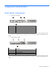
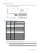
Component identification Front panel components • Two-bay LFF drive model Item Description 1 Optical drive blank 2 Serial number/iLO information pull tab* 3 USB 2.0 connectors 4 LFF drives (8.89 cm, 3.5 in) * The serial number/iLO information pull tab is double-sided. The top side shows the server serial number, and the reverse side shows the default iLO account information. The same information is printed on a label attached to the chassis.
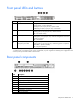
Front panel LEDs and buttons Item Description Status 1 Health LED Solid green = Normal Flashing amber = System degraded Flashing red (1 Hz/cycle per sec) = System critical Fast-flashing red (4 Hz/cycles per sec) = Power fault* 2 NIC status LED Solid green = Link to network Flashing green (1 Hz/cycle per sec) = Network active Off = No network activity 3 UID button/LED Solid blue = Activated Flashing blue (1 Hz/cycle per sec) = Remote management or firmware upgrade in progress Off = Deactivated 4
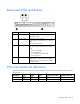
Rear panel LEDs and buttons Item Description Status 1 NIC link LED Solid green = Link exists Off = No link exists 2 NIC status LED Solid green = Link to network Flashing green (1 Hz/cycle per sec) = Network active Off = No network activity 3 Power supply LED Solid green = Normal Off = One or more of the following conditions exists: • • • • 4 UID button/LED Power Power Power Power is unavailable supply failed supply is in standby mode supply error Solid blue = Activated Flashing blue (1 Hz/c
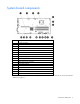
System board components Item Description 1 PCI riser connector* 2 TPM connector 3 microSD card slot 4 Processor socket 5 Fan connector 2 6 Fan connector 1 7 DIMM slots 8 4-pin power supply connector 9 System battery 10 Front I/O module connector 11 24-pin power supply connector 12 26-pin PDB connector 13 SATA connector 14 Mini-SAS connector 15 Fan connector 3 16 Internal USB 2.
DIMM slot locations DIMM slots are numbered sequentially (1 through 4) for the processor. The supported AMP modes use the letter assignments for population guidelines. System maintenance switch Position Default Function S1 Off Off = iLO 4 security is enabled. On = iLO 4 security is disabled. S2 Off Off = System configuration can be changed. On = System configuration is locked. S3 Off Reserved S4 Off Reserved S5 Off Off = Power-on password is enabled. On = Power-on password is disabled.
NMI functionality An NMI crash dump creates a crash dump log before resetting a system which is not responding. Crash dump log analysis is an essential part of diagnosing reliability problems, such as failures of operating systems, device drivers, and applications. Many crashes freeze a system, and the only available action for administrators is to restart the system.
Item 4 LED Drive status Status Definition Off Removing the drive does not cause a logical drive to fail. Solid green The drive is a member of one or more logical drives. Flashing green The drive is rebuilding or performing a RAID migration, strip size migration, capacity expansion, or logical drive extension, or is erasing. Flashing amber/green The drive is a member of one or more logical drives and predicts the drive will fail.
1 - Amber 2 - Green 3 - Green Interpretation Flashing 1 Hz Flashing 1 Hz On A power error occurred during the previous or current boot. Data may be corrupt. Flashing 1 Hz On Off An overtemperature condition exists. Flashing 2 Hz Flashing 2 Hz Off The capacitor pack is not attached. Flashing 2 Hz Flashing 2 Hz On The capacitor has been charging for 10 minutes, but has not reached sufficient charge to perform a full backup.
Operations Power up the server 1. Connect each power cord to the server. 2. Connect each power cord to the power source. 3. Press the Power On/Standby button. The server exits standby mode and applies full power to the system. The system power LED changes from amber to green. Power down the server Before powering down the server for any upgrade or maintenance procedures, perform a backup of critical server data and programs.
IMPORTANT: The requirement of extending or removing the server from the rack when performing installation and maintenance procedures depends on the rail system used: • If using a ball-bearing rail system, you can perform most installations and maintenance by simply extending the server from the rack. • If using a friction rail system, to perform installations or maintenance that requires access panel removal, remove the server from the rack. 1. Power down the server (on page 14). 2.
11. Install the rack rail cable ties ("Installing the rack rail cable ties" on page 27). Remove the server from the rack WARNING: This server is very heavy. To reduce the risk of personal injury or damage to the equipment: • Observe local occupational health and safety requirements and guidelines for manual material handling. • Get help to lift and stabilize the product during installation or removal, especially when the product is not fastened to the rails.
Remove the security bezel (optional) To access the front panel components, unlock and then remove the security bezel. The security bezel is only supported in servers that have the quick-release lever type rack ear option (PN 725269-001) installed. Remove the access panel WARNING: To reduce the risk of personal injury from hot surfaces, allow the drives and the internal system components to cool before touching them. CAUTION: Do not operate the server for long periods with the access panel open or removed.
2. Close the access panel latch. The access panel slides to a closed position. 3. Use a T-15 Torx screwdriver to tighten the access panel latch screw. Remove the air baffle CAUTION: For proper cooling, do not operate the server without the access panel, baffles, expansion slot covers, or blanks installed. If the server supports hot-plug components, minimize the amount of time the access panel is open. 1. Power down the server (on page 14). 2. Remove the power from the server: a.
Install the air baffle 1. Place the air baffle on top of the server. 2. Install the access panel (on page 17). 3. Do one of the following: o Slide the server into the rack. o Install the server into the rack ("Installing the server into the rack" on page 26). 4. Connect the peripheral devices to the server. 5. Connect the power cord to the server. 6. Connect the power cord to the power source. 7. Power up the server (on page 14). Remove the PCI riser cage 1.
6. Lift the PCI riser cage to unseat the PCI riser board. Install the PCI riser cage CAUTION: To prevent damage to the server or expansion boards, power down the server, and disconnect all power cords before removing or installing the PCI riser cage. 1. Use the guide pins on the system board and on the rear panel to align the PCI riser cage, and then press the PCI riser cage down. 2. Install the access panel (on page 17). 3. Do one of the following: o Slide the server into the rack.
4. Connect all necessary external cabling to the expansion board. For more information on these cabling requirements, see the documentation that ships with the option. 5. Connect the peripheral devices to the server. 6. Connect the power cord to the server. 7. Connect the power cord to the power source. 8. Power up the server (on page 14).
Setup Optional installation services Delivered by experienced, certified engineers, HP Care Pack services help you keep your servers up and running with support packages tailored specifically for HP ProLiant systems. HP Care Packs let you integrate both hardware and software support into a single package. A number of service level options are available to meet your needs.
• Leave a minimum clearance of 63.5 cm (25 inches) in front of the rack. • Leave a minimum clearance of 76.2 cm (30 inches) behind the rack. • Leave a minimum clearance of 121.9 cm (48 inches) from the back of the rack to the back of another rack or row of racks. HP servers draw in cool air through the front and expel warm air through the rear.
Power requirements Installation of this equipment must comply with local and regional electrical regulations governing the installation of information technology equipment by licensed electricians. This equipment is designed to operate in installations covered by NFPA 70, 1999 Edition (National Electric Code) and NFPA-75, 1992 (code for Protection of Electronic Computer/Data Processing Equipment).
WARNING: This server is very heavy. To reduce the risk of personal injury or damage to the equipment: • Observe local occupational health and safety requirements and guidelines for manual material handling. • Get help to lift and stabilize the product during installation or removal, especially when the product is not fastened to the rails. HP recommends that a minimum of two people are required for all rack server installations.
WARNING: When installing a server in a telco rack, be sure that the rack frame is adequately secured at the top and bottom to the building structure. Identifying the contents of the server shipping carton Unpack the server shipping carton and locate the materials and documentation necessary for installing the server. All the rack mounting hardware necessary for installing the server into the rack is included with the rack or the server.
CAUTION: Always plan the rack installation so that the heaviest item is on the bottom of the rack. Install the heaviest item first, and continue to populate the rack from the bottom to the top. To install the server in an HP, Compaq-branded, Telco, or a third-party rack: 1. Install the server and cable management arm option into the rack. See the documentation that ships with the Quick Deploy Rail System.
b. To secure the cable tie, loop the end through the plastic buckle on the other end. c. To secure the power cord, repeat steps a and b, using the other cable tie. When multiple cable ties are used in the same rack, stagger the cable tie location, so that the ties are adjacent to each other when viewed from top to bottom. This positioning will enable the rack rail to slide easily in and out of the rack. Powering on and selecting boot options 1. Connect the Ethernet cable. 2.
o If you do not need to modify the server configuration and are ready to install the system software, press F10 to access Intelligent Provisioning. NOTE: If an HP Smart Array controller has been added or is embedded in the system, the controller defaults to a RAID configuration based on the size and number of drives installed. For more information on modifying the controller default settings, see the documentation on the Documentation CD.
Setting up the HP PS1810-24G Switch (optional) If you intend to use the server with the companion HP PS1810-24G Switch, follow the procedures in this section. For more information on switch-related settings and operational procedures, see the documentation for your switch model on the HP website (http://www.hp.com/networking/support). Mounting the switch with the server Mount the switch in a rack, on a wall, or on top of or under a horizontal surface.
2. Connect an Ethernet cable to the server dedicated iLO connector, and then connect the cable to any switch network port. To establish an Ethernet connection with iLO functionality by using the shared iLO connector: 1. Access the iLO RBSU by rebooting the server, and then pressing F8 during POST. 2. Under the Network menu, select the NIC and TCP/IP option.
3. Set the Network Interface Adapter field to Shared Network Port — LOM. 4. To save the change, press F10. 5. To close the iLO RBSU, under the File menu, select the Exit option. 6. Connect an Ethernet cable to the switch, and then connect the cable to a network jack. 7. Connect an Ethernet cable to the server NIC 1/shared iLO connector, and then connect the cable to any switch network port. Completing the switch Self-Test 1. Connect the power adapter to the switch. 2.
o Link/Act LED on the switch network port that is being used—Initially, solid green to indicate successful connection, and then flashing green to indicate active communication with the network. o Fault LED—Remains off to indicate successful Self-Test completion. For more information on the location of the switch LEDs and their behavior during the Self-Test process, see the switch documentation.
Hardware options installation Introduction If more than one option is being installed, read the installation instructions for all the hardware options and identify similar steps to streamline the installation process. WARNING: To reduce the risk of personal injury from hot surfaces, allow the drives and the internal system components to cool before touching them. CAUTION: To prevent damage to electrical components, properly ground the server before beginning any installation procedure.
For more information about product features, specifications, options, configurations, and compatibility, see the product QuickSpecs on the HP website (http://www.hp.com/go/qs). Drive installation guidelines When adding drives to the server, observe the following general guidelines: • The system automatically sets all device numbers. • Populate drive bays, based on the drive numbering sequence. Start from the drive bay with the lowest device number ("Drive numbering" on page 11).
5. Install the drive in the carrier. 6. Install the drive. CAUTION: To prevent improper cooling and thermal damage, do not operate the server unless all bays are populated with either a component or a blank. 7. Connect the power cord to the server. 8. Connect the power cord to the power source. 9. Power up the server (on page 14). To configure arrays, see the HP Smart Storage Administrator User Guide on the HP website (http://www.hp.com/go/smartstorage/docs).
1. Remove the drive blank. 2. Prepare the drive. 3. Install the drive. 4. Determine the status of the drive from the drive LED definitions ("Hot-plug drive LED definitions" on page 11). To configure arrays, see the HP Smart Storage Administrator User Guide on the HP website (http://www.hp.com/go/smartstorage/docs). Controller options The server ships with an embedded Smart Array B120i controller.
Upgrade options exist for an integrated array controller. For a list of supported options, see the product QuickSpecs on the HP website (http://www.hp.com/go/qs). To configure arrays, see the HP Smart Storage Administrator User Guide on the HP website (http://www.hp.com/go/smartstorage/docs). The server supports FBWC. FBWC consists of a cache module and a capacitor pack. The DDR cache module buffers and stores data being written by the controller.
5. Remove the PCI riser cage (on page 19). 6. If you intend to use an FBWC module and capacitor pack, install these options now ("Installing the FBWC module and capacitor pack" on page 39). 7. Install the storage controller in the riser board slot 1. 8. Connect all necessary internal cables to the storage controller. For internal drive cabling information, see "Storage cabling (on page 55)." 9. Install the PCI riser cage (on page 20). 10. Install the access panel (on page 17). 11.
a. Open the capacitor pack holder. b. Position the capacitor pack in the holder. c. Close the capacitor pack holder. CAUTION: When connecting or disconnecting the capacitor pack cable, the connectors on the cache module and cable are susceptible to damage. Avoid excessive force and use caution to avoid damage to these connectors. 7. Connect the capacitor pack cable to the cache module.
8. Install the cache module on the storage controller. 9. Install the storage controller ("Installing a storage controller" on page 38). 10. Install the PCI riser cage (on page 20). 11. Use the chassis cable clip to secure the excess length of the capacitor pack cable. 12. Install the access panel (on page 17). 13. Do one of the following: o Slide the server into the rack. o Install the server into the rack ("Installing the server into the rack" on page 26). 14.
Optical drive option For more information about product features, specifications, options, configurations, and compatibility, see the product QuickSpecs on the HP website (http://www.hp.com/go/qs). To install the component: 1. Power down the server (on page 14). 2. Remove the power from the server: a. Disconnect the power cord from the power source. b. Disconnect the power cord from the server. 3. Do one of the following: o Extend the server from the rack (on page 14).
7. o Two-bay LFF drive model (using the HP 250 W Integrated Power Supply or HP 300 W Integrated Power Supply) o Four-bay SFF drive model (using the HP 750 W CS -48 V DC Power Supply) Connect the optical drive SATA Y-cable: a. Connect the common end of the Y-cable to the optical drive. b. Connect the power end of the Y-cable to the power supply four-pin (1x4) cable. c.
— Two-bay LFF drive model (uses the HP 250 W Integrated Power Supply or HP 300 W Integrated Power Supply) — Four-bay SFF drive model (uses the HP 750 W CS -48 V DC Power Supply) 8. Install the access panel (on page 17). 9. Do one of the following: o Slide the server into the rack. o Install the server into the rack ("Installing the server into the rack" on page 26). 10. Connect the peripheral devices to the server. 11. Connect the power cord to the server. 12.
Memory options The server memory subsystem supports UDIMMs only. UDIMMs represent the most basic type of memory module and offer lower latency and (relatively) low power consumption, but are limited in capacity. The server supports dual-rank, PC3-10600E/PC3-12800E (DDR3 ECC) DIMMs operating at 1333 MHz or 1600 MHz speed. Memory speed depends on the type of processor and the number of DIMMs installed in the server. Installed DIMMs can operate at either 1600 MT/s or 1333 MT/s.
Item Description Definition 3 Data width x4 = 4-bit x8 = 8-bit 4 Voltage rating L = Low voltage (1.35V) U = Ultra low voltage (1.25V) Blank or omitted = Standard 5 Memory speed 12800 = 1600-MT/s 10600 = 1333-MT/s 8500 = 1066-MT/s 6 DIMM type R = RDIMM (registered) E = UDIMM (unbuffered with ECC) L = LRDIMM (load reduced) For more information about product features, specifications, options, configurations, and compatibility, see the product QuickSpecs on the HP website (http://www.hp.
General DIMM slot population guidelines • The server supports two memory channels with two DIMM slots per channel: o Memory channel 1 consists of the two DIMMs that are closest to the processor. o Memory channel 2 consists of the two DIMMs that are located farthest from the processor. • White DIMM slots denote the first slot of a channel (3-A, 1-B). • The server supports up to 32 GB of system memory using four 8 GB 1600 MT/s ECC UDIMMs.
7. Align the notch on the bottom edge of the memory module with the keyed surface of the DIMM slot, and then fully press the memory module into the slot until the latches snap back into place. 8. Install the air baffle (on page 19). 9. Install the access panel (on page 17). 10. Do one of the following: o Slide the server into the rack. o Install the server into the rack ("Installing the server into the rack" on page 26). 11. Connect the peripheral devices to the server. 12.
b. Disconnect the power cord from the server. 3. Do one of the following: o Extend the server from the rack (on page 14). o Remove the server from the rack (on page 16). 4. Remove the access panel (on page 17). 5. Remove the PCI riser cage (on page 19). 6. Identify the expansion slot compatible with the new option, and then remove the cover opposite that slot. 7. Verify that any switches or jumpers on the expansion board are set properly.
Internal USB connector option To install the component: 1. Power down the server (on page 14). 2. Remove the power from the server: a. Disconnect the power cord from the power source. b. Disconnect the power cord from the server. 3. Do one of the following: o Extend the server from the rack (on page 14). o Remove the server from the rack (on page 16). 4. Remove the access panel (on page 17). 5. Install the internal USB connector. 6.
c. Use the chassis cable clip to secure the excess length of the internal USB connector cable. 8. If removed, install the PCI riser cage (on page 20). 9. Install the access panel (on page 17). 10. Do one of the following: o Slide the server into the rack. o Install the server into the rack ("Installing the server into the rack" on page 26). 11. Connect the peripheral devices to the server. 12. Connect the power cord to the server. 13. Connect the power cord to the power source. 14.
When installing or replacing a TPM, observe the following guidelines: • Do not remove an installed TPM. Once installed, the TPM becomes a permanent part of the system board. • When installing or replacing hardware, HP service providers cannot enable the TPM or the encryption technology. For security reasons, only the customer can enable these features. • When returning a system board for service replacement, do not remove the TPM from the system board.
6. Install the TPM board. Press down on the connector to seat the board ("System board components" on page 9). 7. Install the TPM security rivet by pressing the rivet firmly into the system board. 8. If removed, install the PCI riser cage (on page 20). 9. Install the access panel (on page 17). 10. Do one of the following: o Slide the server into the rack. o Install the server into the rack ("Installing the server into the rack" on page 26). 11. Connect the peripheral devices to the server.
Retaining the recovery key/password The recovery key/password is generated during BitLocker setup, and can be saved and printed after BitLocker is enabled. When using BitLocker, always retain the recovery key/password. The recovery key/password is required to enter Recovery Mode after BitLocker detects a possible compromise of system integrity.
Cabling Cabling overview This section provides guidelines that help you make informed decisions about cabling the server and hardware options to optimize performance. For information on cabling peripheral components, refer to the white paper on high-density deployment at the HP website (http://www.hp.com/products/servers/platforms). CAUTION: When routing cables, always be sure that the cables are not in a position where they can be pinched or crimped.
• Mini-SAS cable connected to a storage controller in the full-height expansion slot Item Description 1 Power cable 2 Capacitor pack cable 3 Mini-SAS cable Two-bay LFF hot-plug drive cage cabling • Mini-SAS cable connected to the system board Item Description 1 Power cable 2 Mini-SAS cable Cabling 56
• Mini-SAS cable connected to a storage controller in the full-height expansion slot Item Description 1 Power cable 2 Capacitor pack cable 3 Mini-SAS cable Four-bay SFF hot-plug drive cage cabling (AC power supply) The HP 250 W Integrated Power Supply and HP 300 W Integrated Power Supply is used in the following drive configurations: • Mini-SAS cable connected to the system board Cabling 57
Item Description 1 Power cable 2 Mini-SAS cable • Mini-SAS cable connected to a storage controller in the full-height expansion slot Item Description 1 Power cable 2 Capacitor pack cable 3 Mini-SAS cable The HP 750 W CS -48 V DC Power Supply (94% efficiency) with PDB is used in the following drive configurations: • Mini-SAS cable connected to the system board Cabling 58
Item Description 1 Power cable 2 Mini-SAS cable • Mini-SAS cable connected to a storage controller in the full-height expansion slot Item Description 1 Power cable 2 Capacitor pack cable 3 Mini-SAS cable Cabling 59
Optical drive cabling • Two-bay LFF drive model (uses the HP 250 W Integrated Power Supply or HP 300 W Integrated Power Supply) Item Description 1 Common end of the optical drive SATA Y-cable 2 4-pin power connector of the optical drive SATA Y-cable 3 SATA connector of the optical drive SATA Y-cable • Four-bay SFF drive model (uses the HP 750 W CS -48 V DC Power Supply) Item Description 1 Common end of the optical drive SATA Y-cable 2 4-pin power connector of the optical drive SATA Y-cable
Item Description 3 SATA connector of the optical drive SATA Y-cable Power supply cabling HP 250 W Integrated Power Supply cabling • HP 250 W Integrated Power Supply cabling in a two-bay, LFF, non-hot-plug drive model Item Description 1 24-pin system board power cable 2 4-pin system board power cable • HP 250 W Integrated Power Supply cabling in a two-bay, LFF, hot-plug drive model Cabling 61
Item Description 1 24-pin system board power cable 2 4-pin system board power cable • HP 250 W Integrated Power Supply cabling in a four-bay, SFF, hot-plug drive model Item Description 1 24-pin system board power cable 2 4-pin system board power cable HP 300 W Integrated Power Supply cabling • HP 300 W Integrated Power Supply cabling in a two-bay LFF non-hot-plug drive model Cabling 62
Item Description 1 24-pin system board power cable 2 4-pin system board power cable • HP 300 W Integrated Power Supply cabling in a two-bay LFF hot-plug drive model Item Description 1 24-pin system board power cable 2 4-pin system board power cable • HP 300 W Integrated Power Supply cabling in a four-bay SFF hot-plug drive model Item Description 1 24-pin system board power cable 2 4-pin system board power cable Cabling 63
HP 750 W CS -48 V DC Power Supply (with PDB) cabling Item Description 1 4-pin system board power cable 2 26-pin PDB cable 3 24-pin system board power cable Internal USB cabling Cabling 64
Front I/O board cabling Cabling 65
Software and configuration utilities Server mode The software and configuration utilities presented in this section operate in online mode, offline mode, or in both modes.
Using iLO 4, you can do the following: • Access a high-performance and secure Integrated Remote Console to the server from anywhere in the world if you have a network connection to the server. • Use the shared .NET Integrated Remote Console to collaborate with up to four server administrators. • Remotely mount high-performance Virtual Media devices to the server. • Securely and remotely control the power state of the managed server.
The data that is collected is managed according to the HP Data Privacy policy. For more information see the HP website (http://www.hp.com/go/privacy). The Active Health System, in conjunction with the system monitoring provided by Agentless Management or SNMP Pass-thru, provides continuous monitoring of hardware and configuration changes, system status, and service alerts for various server components.
For more information about the prerequisites, supported hardware, and associated operating systems for central connect, see HP Insight Remote Support Release Notes on the HP website (http://www.hp.com/go/insightremotesupport/docs).
• Intelligent Provisioning assists with the OS installation process by preparing the system for installing "off-the-shelf" and HP branded versions of operating system software and integrating optimized HP ProLiant server support software. • Intelligent Provisioning provides maintenance-related tasks using the Perform Maintenance window. • Intelligent Provisioning provides installation help for Microsoft Windows, Red Hat and SUSE Linux, and VMware operating systems.
• You want to install a new operating system on a server with an existing operating system. • You encounter an error when completing the steps of a factory-installed operating system installation. To access the Erase Utility, click the Perform Maintenance icon from the Intelligent Provisioning home screen, and then select Erase. For more information about the Erase Utility, see the HP Intelligent Provisioning User Guide on the HP website (http://www.hp.com/go/intelligentprovisioning/docs).
For more information on RBSU, see the HP ROM-Based Setup Utility User Guide on the Documentation CD or the HP RBSU Information Library (http://www.hp.com/go/rbsu/docs). Using RBSU To use RBSU, use the following keys: • To access RBSU, press the F9 key during power-up when prompted. • To navigate the menu system, use the arrow keys. • To make selections, press the Enter key. • To access Help for a highlighted configuration option, press the F1 key.
Boot options Near the end of the boot process, the boot options screen is displayed. This screen is visible for several seconds before the system attempts to boot from a supported boot device. During this time, you can do the following: • Access RBSU by pressing the F9 key. • Access Intelligent Provisioning Maintenance Menu by pressing the F10 key. • Access the boot menu by pressing the F11 key. • Force a PXE Network boot by pressing the F12 key.
Utilities and features Array Configuration Utility ACU is a utility with the following features: • Runs as a local application or remote service accessed through the HP System Management Homepage • Supports online array capacity expansion, logical drive extension, assignment of online spares, and RAID or stripe size migration • Suggests the optimum configuration for an unconfigured system • For supported controllers, provides access to licensed features, including: o Moving and deleting individual
HP Smart Storage Administrator HP SSA is a configuration and management tool for HP Smart Array controllers. Starting with HP ProLiant Gen8 servers, HP SSA replaces ACU with an enhanced GUI and additional configuration features. HP SSA exists in three interface formats: the HP SSA GUI, the HP SSA CLI, and HP SSA Scripting. Although all formats provide support for configuration tasks, some of the advanced tasks are available in only one format.
For more information, go to the HP website (http://www.hp.com/go/hpsc) and click on Drivers, Software & Firmware. Then, enter your product name in the Find an HP product field and click Go. Automatic Server Recovery ASR is a feature that causes the system to restart when a catastrophic operating system error occurs, such as a blue screen, ABEND (does not apply to HP ProLiant DL980 Servers), or panic.
Keeping the system current Access to HP Support Materials Access to some updates for HP ProLiant Servers may require product entitlement when accessed through the HP Support Center support portal. HP recommends that you have an HP Passport set up with relevant entitlements. For more information, see the HP website (http://h20564.www2.hp.com/portal/site/hpsc/public/kb/docDisplay/?docId=c03859703). Drivers IMPORTANT: Always perform a backup before installing or updating device drivers.
• VCA compares installed software versions on the node with updates available in the VCRM managed repository. Administrators configure VCA to point to a repository managed by VCRM. For more information about version control tools, see the HP Systems Insight Manager User Guide, the HP Version Control Agent User Guide, and the HP Version Control Repository User Guide on the HP website (http://www.hp.com/go/hpsim).
Troubleshooting Troubleshooting resources The HP ProLiant Gen8 Troubleshooting Guide, Volume I: Troubleshooting provides procedures for resolving common problems and comprehensive courses of action for fault isolation and identification, issue resolution, and software maintenance on ProLiant servers and server blades. To view the guide, select a language: • English (http://www.hp.com/support/ProLiant_TSG_v1_en) • French (http://www.hp.com/support/ProLiant_TSG_v1_fr) • Spanish (http://www.hp.
System battery replacement If the server no longer automatically displays the correct date and time, then replace the battery that provides power to the real-time clock. Under normal use, battery life is 5 to 10 years. WARNING: The computer contains an internal lithium manganese dioxide, a vanadium pentoxide, or an alkaline battery pack. A risk of fire and burns exists if the battery pack is not properly handled. To reduce the risk of personal injury: • • • • Do not attempt to recharge the battery.
IMPORTANT: Replacing the system board battery resets the system ROM to its default configuration. After replacing the battery, reconfigure the system through RBSU. To replace the component, reverse the removal procedure. For more information about battery replacement or proper disposal, contact an authorized reseller or an authorized service provider.
Regulatory information Safety and regulatory compliance For safety, environmental, and regulatory information, see Safety and Compliance Information for Server, Storage, Power, Networking, and Rack Products, available at the HP website (http://www.hp.com/support/Safety-Compliance-EnterpriseProducts). Belarus Kazakhstan Russia marking Manufacturer Hewlett-Packard Company, Address: 3000 Hanover Street, Palo Alto, California 94304, U.S.
Valid date formats include the following: • YWW, where Y indicates the year counting from within each new decade, with 2000 as the starting point. For example, 238: 2 for 2002 and 38 for the week of September 9. In addition, 2010 is indicated by 0, 2011 by 1, 2012 by 2, 2013 by 3, and so forth. • YYWW, where YY indicates the year, using a base year of 2000. For example, 0238: 02 for 2002 and 38 for the week of September 9.
Electrostatic discharge Preventing electrostatic discharge To prevent damaging the system, be aware of the precautions you need to follow when setting up the system or handling parts. A discharge of static electricity from a finger or other conductor may damage system boards or other static-sensitive devices. This type of damage may reduce the life expectancy of the device. To prevent electrostatic damage: • Avoid hand contact by transporting and storing products in static-safe containers.
Specifications Environmental specifications Specification Value Temperature range* Operating 10°C to 35°C (50°F to 95°F) Non-operating -30°C to 60°C (-22°F to 140°F) Relative humidity (non-condensing) Operating, maximum wet bulb 10% to 90% temperature of 28°C (82.4°F) Non-operating, maximum wet 5% to 95% bulb temperature of 38.7°C (101.7°F) * All temperature ratings shown are for sea level. An altitude derating of 1°C per 304.8 m (1.8°F per 1,000 ft) to 3048 m (10,000 ft) is applicable.
Rated input power 312 W; 1,066 Btu/hr Power supply output — Efficiency 80% Maximum peak power 250 W HP 300 W Integrated Power Supply Specification Value Input requirements — Rated input voltage 100 V AC to 127 V AC 200 V AC to 240 V AC Rated input frequency 50 Hz–60 Hz Rated input current 6 A max at 100 V AC 3 A max at 200 V AC Rated input power 600 W Power supply output — Efficiency 80% Maximum peak power 350 W (duration less 10 sec at 25°C) HP 750 W CS -48 V DC Power Supply (94%
• This equipment must be located in the same immediate area (such as adjacent cabinets) as any other equipment that has a connection between the earthed conductor of the same DC supply circuit and the earthing conductor, and also the point of earthing of the DC system. The DC system must be earthed elsewhere. • The DC supply source is to be located within the same premises as the equipment.
Support and other resources Before you contact HP Be sure to have the following information available before you call HP: • Active Health System log (HP ProLiant Gen8 or later products) Download and have available an Active Health System log for 3 days before the failure was detected. For more information, see the HP iLO 4 User Guide or HP Intelligent Provisioning User Guide on the HP website (http://www.hp.com/go/ilo/docs).
providers or service partners) identifies that the repair can be accomplished by the use of a CSR part, HP will ship that part directly to you for replacement. There are two categories of CSR parts: • Mandatory—Parts for which customer self repair is mandatory. If you request HP to replace these parts, you will be charged for the travel and labor costs of this service. • Optional—Parts for which customer self repair is optional. These parts are also designed for customer self repair.
Pour plus d'informations sur le programme CSR de HP, contactez votre Mainteneur Agrée local. Pour plus d'informations sur ce programme en Amérique du Nord, consultez le site Web HP (http://www.hp.com/go/selfrepair). Riparazione da parte del cliente Per abbreviare i tempi di riparazione e garantire una maggiore flessibilità nella sostituzione di parti difettose, i prodotti HP sono realizzati con numerosi componenti che possono essere riparati direttamente dal cliente (CSR, Customer Self Repair).
HINWEIS: Einige Teile sind nicht für Customer Self Repair ausgelegt. Um den Garantieanspruch des Kunden zu erfüllen, muss das Teil von einem HP Servicepartner ersetzt werden. Im illustrierten Teilekatalog sind diese Teile mit „No“ bzw. „Nein“ gekennzeichnet. CSR-Teile werden abhängig von der Verfügbarkeit und vom Lieferziel am folgenden Geschäftstag geliefert. Für bestimmte Standorte ist eine Lieferung am selben Tag oder innerhalb von vier Stunden gegen einen Aufpreis verfügbar.
sustituciones que lleve a cabo el cliente, HP se hará cargo de todos los gastos de envío y devolución de componentes y escogerá la empresa de transporte que se utilice para dicho servicio. Para obtener más información acerca del programa de Reparaciones del propio cliente de HP, póngase en contacto con su proveedor de servicios local. Si está interesado en el programa para Norteamérica, visite la página web de HP siguiente (http://www.hp.com/go/selfrepair).
Opcional – Peças cujo reparo feito pelo cliente é opcional. Essas peças também são projetadas para o reparo feito pelo cliente. No entanto, se desejar que a HP as substitua, pode haver ou não a cobrança de taxa adicional, dependendo do tipo de serviço de garantia destinado ao produto. OBSERVAÇÃO: Algumas peças da HP não são projetadas para o reparo feito pelo cliente. A fim de cumprir a garantia do cliente, a HP exige que um técnico autorizado substitua a peça.
Support and other resources 94
Support and other resources 95
Acronyms and abbreviations ABEND abnormal end ACU Array Configuration Utility ADM Advanced Data Mirroring AMP Advanced Memory Protection ASR Automatic Server Recovery CSA Canadian Standards Association CSR Customer Self Repair DDR3 double data rate-3 EAC EuroAsian Economic Commission FBWC flash-backed write cache HDIMM HyperCloud DIMM HP CS HP Common Slot (power supply) Acronyms and abbreviations 96
HP SIM HP Systems Insight Manager HP SUM HP Smart Update Manager IEC International Electrotechnical Commission iLO Integrated Lights-Out IML Integrated Management Log ISO International Organization for Standardization LFF large form factor LOM LAN on Motherboard LRDIMM load reduced dual in-line memory module NMI nonmaskable interrupt NVRAM nonvolatile memory OA Onboard Administrator ORCA Option ROM Configuration for Arrays PCIe Peripheral Component Interconnect Express Acronyms and abbreviatio
PDB power distribution board PDU power distribution unit POST Power-On Self Test PXE preboot execution environment RBSU ROM-Based Setup Utility RDIMM registered dual in-line memory module RDP Rapid Deployment Pack RoHS Restriction of Hazardous Substances SAS serial attached SCSI SATA serial ATA SD Secure Digital SELV separated extra low voltage SFF small form factor SPP HP Service Pack for ProLiant Acronyms and abbreviations 98
SSA HP Smart Storage Administrator TMRA recommended ambient operating temperature TNV telephone network voltage TPM Trusted Platform Module UDIMM unregistered dual in-line memory module UID unit identification USB universal serial bus VC Virtual Connect VCA Version Control Agent VCRM Version Control Repository Manager Acronyms and abbreviations 99
Documentation feedback HP is committed to providing documentation that meets your needs. To help us improve the documentation, send any errors, suggestions, or comments to Documentation Feedback (mailto:docsfeedback@hp.com). Include the document title and part number, version number, or the URL when submitting your feedback.
Index A access panel 17 Active Health System 66, 67 air baffle 18, 19 airflow requirements 22, 23 ambient temperature 23 Array Configuration Utility (ACU) 74, 75 authorized reseller 88 auto-configuration process 72 Automatic Server Recovery (ASR) 76 B Basic Input/Output System (BIOS) 66, 75 Belarus Kazakhstan Russia marking 82 BIOS upgrade 66, 75 boot options 73 C cable management arm 26 cabling, drive 55, 56 cabling, FBWC 55, 56 cabling, front I/O 65 cabling, internal power 61 cabling, internal USB 64 ca
H hardware options installation 26, 34 health driver 76 health LED 7 help resources 88 hot-plug drive, installing 36 HP Care Pack Services 22, 78 HP Collaborative Support 78 HP contact information 88 HP Insight Diagnostics 70 HP Insight Remote Support software 68, 78 HP Proactive Care 78 HP Service Pack for ProLiant 66, 70, 71 HP Smart Storage Administrator (HP SSA) 75 HP Smart Update Manager overview 66, 71 HP SmartMemory 45 HP Support Center 78 HP Systems Insight Manager (SIM) 70 HP technical support 78,
Q QuickSpecs 66 R rack installation 22 rack rail cable ties 27 rack warnings 25 rack, extending server from 14 RAID configuration 74, 75 Rapid Deployment Pack (RDP) 22 rear panel buttons 8 rear panel components 7 rear panel LEDs 8 recommended ambient operating temperature (TMRA) 23 redundant ROM 76 re-entering the server serial number 73 registering the product 29 regulatory compliance information 82 removing server from rack 16 required tools 26 requirements, airflow 22 requirements, electrical grounding