HP ProLiant DL320s Server User Guide Part Number 431185-003 April 2007 (Third Edition)
© Copyright 2006, 2007 Hewlett-Packard Development Company, L.P. The information contained herein is subject to change without notice. The only warranties for HP products and services are set forth in the express warranty statements accompanying such products and services. Nothing herein should be construed as constituting an additional warranty. HP shall not be liable for technical or editorial errors or omissions contained herein. Microsoft, Windows, and Windows NT are U.S.
Contents Component identification ............................................................................................................... 6 Front panel LEDs and buttons ...................................................................................................................... 6 SAS and SATA drive numbers..................................................................................................................... 8 SAS and SATA hard drive LEDs.......................................
SAS and SATA hard drive guidelines ............................................................................................... 32 Installing a SAS or SATA hard drive................................................................................................. 33 Installing an expansion board ................................................................................................................... 34 Battery-backed write cache ..................................................................
Federal Communications Commission notice............................................................................................... 74 FCC rating label............................................................................................................................ 75 Class A equipment......................................................................................................................... 75 Class B equipment .....................................................................
Component identification In this section Front panel LEDs and buttons ..................................................................................................................... 6 SAS and SATA drive numbers.................................................................................................................... 8 SAS and SATA hard drive LEDs .................................................................................................................
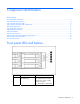
Item Description Status 2 Internal health LED Green = System health is normal. Amber = System is degraded. To identify the component in a degraded state, see system board LEDs. Red = System critical. To identify the component in a critical state, see system board LEDs. Off = System health is normal (when in standby mode). 3 NIC 1 link/activity LED Green = Network link exists. Flashing green = Network link and activity exist. Off = No link to network exists.
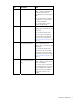
SAS and SATA drive numbers SAS and SATA hard drive LEDs Item Description Status 1 Fault/UID LED Amber = Drive failure Flashing amber = Fault-process activity Blue = Unit identification is active Off = No fault-process activity 2 Online/activity LED Green = Drive activity Flashing green = High activity on the drive or drive is being configured as part of an array Off = No drive activity Component identification 8
SAS and SATA hard drive LED combinations Online/activity LED (green) Fault/UID LED (amber/blue) On, off, or flashing Alternating amber and The drive has failed, or a predictive failure alert has been blue received for this drive; it also has been selected by a management application. On, off, or flashing Steadily blue The drive is operating normally, and it has been selected by a management application. On Amber, flashing regularly (1 Hz) A predictive failure alert has been received for this drive.
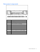
Rear panel components Item Description 1 Power supply 2 USB connectors (2) 3 PCI Express x8 expansion slot 2 (full-length) 4 Video connector 5 Mouse connector 6 Keyboard connector 7 Serial connector 8 iLO 2 NIC 9 PCI Express x1 expansion slot 1 (low-profile, half-length) 10 NIC controller 1 11 NIC controller 2 12 UID button/LED Component identification 10
Rear panel LEDs and buttons Item Description LED color Status 1 Activity LED Green On or flashing = Network activity Off = No network activity 2 Link LED Green On = Linked to network Off = Not linked to network 3 UID LED Blue On = Activated Flashing = Server remotely managed Off = Deactivated System board components Component identification 11
Description Item Description 1 PCI Express x8 connector 10 Fan 3 connector 2 PCI Express x1 connector 11 Fan 4 connector 3 System maintenance switch (on page 12) 12 Main power connector 4 NMI switch ("NMI functionality" on page 13) 13 Processor socket 5 Battery 14 Auxiliary power connector 6 Front panel LED board connector 15 DIMM slot 1 (bank A) 7 Internal USB connector 16 DIMM slot 2 (bank B) 8 Fan 1 connector 17 DIMM slot 3 (bank A) 9 Fan 2 connector 18 DIMM slot 4 (
NMI functionality An NMI crash dump enables administrators to create crash dump files when a system is hung and not responding to traditional debug mechanisms. Crash dump log analysis is an essential part of diagnosing reliability problems, such as hangs in operating systems, device drivers, and applications. Many crashes freeze a system, and the only available action for administrators is to cycle the system power.
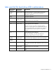
Item LED description Status 3 Fan 1 Amber = One or more fans in this module have failed. Off = All fans in this module are operating normally. 4 Processor Amber = Processor has failed. Off = Processor is operating normally. 5 Fan 2 Amber = One or more fans in this module have failed. Off = All fans in this module are operating normally. 6 Fan 3 Amber = One or more fans in this module have failed. Off = All fans in this module are operating normally.
Internal USB connectors See "Internal USB functionality (on page 54)" for more information. System LEDs and internal health LED combinations When the internal health LED on the front panel illuminates either amber or red, the server is experiencing a health event. Combinations of illuminated system LEDs and the internal health LED indicate system status. The front panel health LEDs indicate only the current hardware status.
System LED and Color Internal Health LED Color Status Amber • DIMM in slot X has reached single-bit correctable error threshold. • DIMM in slot X is in a pre-failure condition. • DIMM in slot X is an unsupported type, but valid memory exists in another bank. DIMM failure, all slots in one bank (amber) Red No valid or usable memory is installed in the system. Overtemperature (amber) Amber The Health Driver has detected a cautionary temperature level.
Item ID Color Description 2 Green Auxiliary Power LED. This LED glows steadily when 3.3V auxiliary voltage is detected. The auxiliary voltage is used to preserve BBWC data and is available any time that the system power cords are connected to a power supply. 3 Amber Battery Health LED. To interpret the illumination patterns of this LED, see the following table. 4 Green BBWC Status LED. To interpret the illumination patterns of this LED, see the following table.
Fan assembly location Component identification 18
Setup In this section Optional installation services ................................................................................................................... 19 Rack planning resources ......................................................................................................................... 20 Optimum environment............................................................................................................................. 20 Rack warnings ............................
For more information on Care Packs, refer to the HP website (http://www.hp.com/hps/carepack/servers/cp_proliant.html). Rack planning resources The rack resource kit ships with all HP branded or Compaq branded 9000, 10000, and H9 series racks. For more information on the content of each resource, refer to the rack resource kit documentation. If you intend to deploy and configure multiple servers in a single rack, refer to the white paper on highdensity deployment at the HP website (http://www.hp.
CAUTION: If a third-party rack is used, observe the following additional requirements to ensure adequate airflow and to prevent damage to the equipment: • Front and rear doors—If the 42U rack includes closing front and rear doors, you must allow 5,350 sq cm (830 sq in) of holes evenly distributed from top to bottom to permit adequate airflow (equivalent to the required 64 percent open area for ventilation).
Electrical grounding requirements The server must be grounded properly for proper operation and safety. In the United States, you must install the equipment in accordance with NFPA 70, 1999 Edition (National Electric Code), Article 250, as well as any local and regional building codes. In Canada, you must install the equipment in accordance with Canadian Standards Association, CSA C22.1, Canadian Electrical Code.
• Phillips screwdriver • Hardware options • Operating system or application software • Keyboard • Mouse • External USB CD-ROM drive • External USB floppy drive • USB key Installing a storage enclosure into the rack To install the server into the rack: 1. Secure the front end of the rails to the rack. IMPORTANT: Do not remove the pins from the ends of the rack rails unless you are converting the rails for use in round-hole racks.
3. Remove the plastic cover from the front of the server. 4. Slide the chassis into the rack. 5. Use the thumbscrews on the front of the chassis to secure it to the rack. 6. Use the shipping bracket to secure the server for shipping: IMPORTANT: Use of the shipping bracket is required only when the rack is shipped with the server installed. a. Loosen the thumbscrew on the shipping bracket. b. Slide the shipping bracket forward until it engages the chassis. c. Tighten the thumbscrew.
Installing hardware options Install any hardware options before initializing the server. For options installation information, refer to the option documentation. For server-specific information, refer to "Hardware options installation (on page 30)." Powering up and configuring IMPORTANT: The F8 key is available only when a supported storage controller is installed in the server. To power up the server, press the Power On/Standby button.
Operations In this section Power up the server ................................................................................................................................ 26 Power down the server............................................................................................................................ 26 Removing and replacing the access panel................................................................................................. 26 Removing the upper tray ...................
3. Slide the access panel and lift off the server. To replace the access panel, reverse the previous steps. Removing the upper tray 1. Power down the server (on page 26). 2. Remove the access panel ("Removing and replacing the access panel" on page 26). CAUTION: Do not detach the cable that connects the battery pack to the cache module. Detaching the cable causes any unsaved data in the cache module to be lost. 3. Remove the battery pack.
4. Loosen the thumbscrews, and lift the upper tray from the server. Removing the PCI riser board assembly CAUTION: To prevent damage to the server or expansion boards, power down the server and remove all AC power cords before removing or installing the PCI riser board assembly. 1. Power down the server (on page 26). 2. Remove the access panel ("Removing and replacing the access panel" on page 26). 3. Remove the upper tray ("Removing the upper tray" on page 27). 4.
Hot-plug fan operation The server supports variable fan speeds. The fans operate at minimum speed until a temperature change requires a fan speed increase to cool the server. The server shuts down in the following scenarios: • At POST: o The BIOS suspends the server for 5 minutes if it detects a cautionary temperature level. If the cautionary temperature level is still detected after 5 minutes, the BIOS performs an orderly shutdown and enters Standby mode.
Hardware options installation In this section Introduction ........................................................................................................................................... 30 Memory options ..................................................................................................................................... 30 Hard drive options .................................................................................................................................
Installing DIMMs Observe the following guidelines when installing additional memory: • DIMMs installed in the server must be unbuffered DDR2 SDRAM, 2.5 V, 64 bits wide, and ECC. • All DIMMs installed must be the same speed (DDR2 PC5300). Do not install DIMMs supporting different speeds. • If only a single DIMM is installed, HP recommends installing it in slot 1A. BIOS detects the DIMM population and sets the system as follows: • Single-bank mode: DIMMs installed in one bank only.
Installing the PCI riser board assembly CAUTION: To prevent damage to the server or expansion boards, power down the server and remove all AC power cords before removing or installing the PCI riser board assembly. 1. Power down the server (on page 26). 2. Remove the access panel ("Removing and replacing the access panel" on page 26). 3. Remove the upper tray ("Removing the upper tray" on page 27). 4. Install the expansion board ("Installing an expansion board" on page 34). 5.
Installing a SAS or SATA hard drive CAUTION: To prevent improper cooling and thermal damage, do not operate the server unless all bays are populated with either a component or a blank. 1. Remove the hard drive blank. 2. Prepare the hard drive.
3. Install the hard drive. IMPORTANT: When the drive is inserted, the drive LEDs flash for 2 seconds to indicate that the drive is seated properly and receiving power. 4. Determine the status of the hard drive from the SAS and SATA hard drive LED combinations (on page 9). Installing an expansion board 1. Power down the server (on page 26). 2. Remove the access panel ("Removing and replacing the access panel" on page 26). 3. Remove the upper tray ("Removing the upper tray" on page 27). 4.
6. Install the PCI riser board assembly ("Installing the PCI riser board assembly" on page 32). 7. Replace the upper tray ("Removing the upper tray" on page 27). 8. Replace the access panel ("Removing and replacing the access panel" on page 26). Battery-backed write cache The HP BBWC protects against hard boot, power, controller, and system board failures.
3. Remove the battery pack. 4. Remove the upper tray ("Removing the upper tray" on page 27). 5. If the existing cache is connected to a battery, observe the BBWC Status LED ("Battery-backed write cache LEDs" on page 16). 6. o If the LED is blinking every 2 seconds, data is still trapped in the cache. Restore system power, and repeat the previous steps. o If the LED is not lit, disconnect the battery cable from the cache. Remove the controller.
7. Remove the cache module from the controller. 8. Install the new cache on the controller. Press firmly above each connector to ensure good electrical contact. If the cache is not properly connected, the controller will not boot. 9. Replace the controller in the server. The controller is installed in expansion slot 2. 10. Replace the upper tray. 11. Install the battery pack into the server. 12. Route the cable, and connect it to the cache module.
13. Replace the access panel ("Removing and replacing the access panel" on page 26). After installing a battery pack, you might see a POST message during reboot, indicating that the array accelerator (cache) is temporarily disabled. This behavior is normal because the new battery pack is likely to have a low charge. You do not need to take any action because the recharge process begins automatically when the battery pack is installed.
5. Connect the DVD-ROM cable to the system board. Installing a rear hard drive option 1. Remove the server from the rack. 2. Remove the access panel ("Removing and replacing the access panel" on page 26). 3. Remove the battery pack. CAUTION: Disconnecting the battery module cable will cause any unsaved data in the cache module to be lost. 4. Loosen the thumbscrews, and lift the upper tray from the server.
5. Disconnect the battery cable from the battery-backed write cache (BBWC) module, and set it aside. See the server user guide for appropriate BBWC handling procedures. 6. Remove all system fans. 7. Loosen the two thumbscrews on the fan assembly and remove the fan cage.
8. Remove the air baffle from the hard drive option tray. 9. Install the battery into the hard drive option tray.
10. Connect the BBWC cable to the cache module. 11. Connect the hard drive cable to port 2 on the controller. NOTE: If a HP Smart Array P800 controller is installed, the hard drive cable must be threaded under the controller assembly.
12. Connect the hard drive option power cable. CAUTION: When routing cables, always be sure that the cables are not in a position where they can be pinched or air flow can be blocked. 13. Attach the small air baffle to the fan cage assembly using the Velcro strap and replace the fan cage in the server.
14. Replace the air baffle on the hard drive option tray. 15. Place the hard drive option tray in the server, and tighten the thumbscrews. 16. Replace the system fans. 17. Replace the access panel ("Removing and replacing the access panel" on page 26). Installing the single power supply option CAUTION: To prevent improper cooling and thermal damage, do not operate the server unless all bays are populated with either a component or a blank.
1. Disconnect the power cord from the power supply and remove the component as indicated. 2. Install the power supply in slot 1 as indicated and install the power supply blank in slot 2.
Cabling In this section Cabling overview................................................................................................................................... 46 Server cable routing ............................................................................................................................... 46 BBWC cable routing...............................................................................................................................
Cabling 47
Software and configuration utilities In this section Configuration tools ................................................................................................................................. 48 HP ProLiant Essentials Rapid Deployment Pack........................................................................................... 50 Option ROM Configuration for Arrays ......................................................................................................
ProLiant BL, ML, and DL servers. The toolkit includes a modular set of utilities and important documentation that describes how to apply these new tools to build an automated server deployment process. Using SmartStart technology, the Scripting Toolkit provides a flexible way to create standard server configuration scripts. These scripts are used to automate many of the manual steps in the server configuration process.
NOTE: If the boot drive is not empty or has been written to in the past, ORCA does not automatically configure the array. You must run ORCA to configure the array settings. Drives installed Drives used RAID level 1 1 RAID 0 2 2 RAID 1 3, 4, 5, or 6 3, 4, 5, or 6 RAID 5 More than 6 0 None To change any ORCA default settings and override the auto-configuration process, press the F8 key when prompted. By default, the auto-configuration process configures the system for the English language.
Option ROM Configuration for Arrays Before installing an operating system, you can use the ORCA utility to create the first logical drive, assign RAID levels, and establish online spare configurations.
5. Enter the serial number. 6. Select Product ID. The following warning is displayed. Warning: The Product ID should ONLY be modified by qualified service personnel. This value should always match the Product ID located on the chassis. 7. Enter the product ID and press the Enter key. 8. Press the Escape key to close the menu. 9. Press the Escape key to exit RBSU. 10. Press the F10 key to confirm exiting RBSU. The server will automatically reboot.
provides seamless integration with HP hardware support by generating and emailing support tickets that deliver a snapshot of the storage system. For more information, and to download the utility, refer to the StorageWorks L&TT website (http://h18006.www1.hp.com/products/storageworks/ltt). Management Agents Management Agents provide the information to enable fault, performance, and configuration management.
• Integrates with other software maintenance, deployment, and operating system tools • Automatically checks for hardware, firmware, and operating system dependencies, and installs only the correct ROM upgrades required by each target server To download the tool and for more information, refer to the HP website (http://h18000.www1.hp.com/support/files/index.html). USB support HP provides both standard USB support and legacy USB support.
Survey Utility Survey Utility, a feature within HP Insight Diagnostics (on page 54), gathers critical hardware and software information on ProLiant servers. This utility supports operating systems that may not be supported by the server. For operating systems supported by the server, refer to the HP website (http://www.hp.com/go/supportos).
identify and prevent potential critical problems. Through remote diagnostic scripts and vital system configuration information collected about your systems, ISEE enables fast restoration of your systems. Install ISEE on your systems to help mitigate risk and prevent potential critical problems. For more information on ISEE, refer to the HP website (http://www.hp.com/hps/hardware/hw_enterprise.html). To download HP ISEE, visit the HP website (http://www.hp.com/hps/hardware/hw_downloads.html).
Care Pack HP Care Pack Services offer upgraded service levels to extend and expand standard product warranty with easy-to-buy, easy-to-use support packages that help you make the most of your server investments. Refer to the Care Pack website (http://www.hp.com/hps/carepack/servers/cp_proliant.html).
Troubleshooting In this section Troubleshooting resources ....................................................................................................................... 58 Pre-diagnostic steps ................................................................................................................................ 58 Loose connections .................................................................................................................................. 61 Service notifications....
Symbols on equipment The following symbols may be placed on equipment to indicate the presence of potentially hazardous conditions. This symbol indicates the presence of hazardous energy circuits or electric shock hazards. Refer all servicing to qualified personnel. WARNING: To reduce the risk of injury from electric shock hazards, do not open this enclosure. Refer all maintenance, upgrades, and servicing to qualified personnel. This symbol indicates the presence of electric shock hazards.
WARNING: To reduce the risk of personal injury or damage to the equipment, be sure that: • The leveling feet are extended to the floor. • The full weight of the rack rests on the leveling feet. • The stabilizing feet are attached to the rack if it is a single-rack installation. • The racks are coupled together in multiple-rack installations. • Only one component is extended at a time. A rack may become unstable if more than one component is extended for any reason.
• Run HP Insight Diagnostics (on page 54) and use the survey page to view the current configuration or to compare it to previous configurations. • Refer to your hardware and software records for information. • Refer to server LEDs and their statuses. Prepare the server for diagnosis 1. Be sure the server is in the proper operating environment with adequate power, air conditioning, and humidity control. Refer to the server documentation for required environmental conditions. 2.
• If problems continue to occur, remove and reinstall each device, checking the connectors and sockets for bent pins or other damage. Service notifications To view the latest service notifications, refer to the HP website (http://www.hp.com/go/bizsupport). Select the appropriate server model, and then click the Troubleshoot a Problem link on the product page.
General diagnosis flowchart The General diagnosis flowchart provides a generic approach to troubleshooting. If you are unsure of the problem, or if the other flowcharts do not fix the problem, use the following flowchart.
Item Refer to 4 The most recent version of a particular server or option firmware is available on the following websites: • HP Support website (http://www.hp.com/support) • HP ROM-BIOS/Firmware Updates website (http://h18023.www1.hp.com/support/files/server/us/romflash.ht ml) 5 "General memory problems are occurring" in the HP ProLiant Servers Troubleshooting Guide located on the Documentation CD or on the HP website (http://www.hp.
Server power-on problems flowchart Symptoms: • The server does not power on. • The system power LED is off or amber.
• The external health LED is red or amber. • The internal health LED is red or amber. NOTE: For the location of server LEDs and information on their statuses, refer to the server documentation.
Software and configuration utilities 67
POST problems flowchart Symptoms: • Server does not complete POST NOTE: The server has completed POST when the system attempts to access the boot device.
OS boot problems flowchart Symptoms: • Server does not boot a previously installed operating system • Server does not boot SmartStart Possible causes: • Corrupted operating system • Hard drive subsystem problem • Incorrect boot order setting in RBSU Software and configuration utilities 69
Item Refer to 1 HP ROM-Based Setup Utility User Guide (http://www.hp.com/servers/smartstart) 2 "POST problems flowchart (on page 68)" 3 • "Hard drive problems" in the HP ProLiant Servers Troubleshooting Guide located on the Documentation CD or on the HP website (http://www.hp.com/support) • Controller documentation 4 "HP Insight Diagnostics (on page 54)" or in the HP ProLiant Servers Troubleshooting Guide located on the Documentation CD or on the HP website (http://www.hp.
Server fault indications flowchart Symptoms: • Server boots, but a fault event is reported by Insight Management Agents (on page 53) • Server boots, but the internal health LED, external health LED, or component health LED is red or amber NOTE: For the location of server LEDs and information on their statuses, refer to the server documentation.
Possible causes: • Improperly seated or faulty internal or external component • Unsupported component installed • Redundancy failure • System overtemperature condition Item Refer to 1 "Management agents (on page 53)" or in the HP ProLiant Servers Troubleshooting Guide located on the Documentation CD or on the HP website (http://www.hp.
POST error messages and beep codes For a complete listing of error messages, refer to the "POST error messages" in the HP ProLiant Servers Troubleshooting Guide located on the Documentation CD or on the HP website (http://www.hp.com/support).
Regulatory compliance notices In this section Regulatory compliance identification numbers ........................................................................................... 74 Federal Communications Commission notice ............................................................................................. 74 Declaration of conformity for products marked with the FCC logo, United States only..................................... 75 Modifications..................................................
FCC rating label The FCC rating label on the device shows the classification (A or B) of the equipment. Class B devices have an FCC logo or ID on the label. Class A devices do not have an FCC logo or ID on the label. After you determine the class of the device, refer to the corresponding statement. Class A equipment This equipment has been tested and found to comply with the limits for a Class A digital device, pursuant to Part 15 of the FCC Rules.
For questions regarding this FCC declaration, contact us by mail or telephone: • Hewlett-Packard Company P. O. Box 692000, Mail Stop 510101 Houston, Texas 77269-2000 • 1281-514-3333 To identify this product, refer to the part, series, or model number found on the product. Modifications The FCC requires the user to be notified that any changes or modifications made to this device that are not expressly approved by Hewlett-Packard Company may void the user’s authority to operate the equipment.
Compliance with these directives implies conformity to applicable harmonized European standards (European Norms) which are listed on the EU Declaration of Conformity issued by Hewlett-Packard for this product or product family. This compliance is indicated by the following conformity marking placed on the product: This marking is valid for non-Telecom products and EU harmonized Telecom products (e.g. Bluetooth). This marking is valid for EU non-harmonized Telecom products.
BSMI notice Korean notice Class A equipment Class B equipment Laser compliance This product may be provided with an optical storage device (that is, CD or DVD drive) and/or fiber optic transceiver. Each of these devices contains a laser that is classified as a Class 1 Laser Product in accordance with US FDA regulations and the IEC 60825-1. The product does not emit hazardous laser radiation. Each laser product complies with 21 CFR 1040.10 and 1040.11 except for deviations pursuant to Laser Notice No.
WARNING: Use of controls or adjustments or performance of procedures other than those specified herein or in the laser product's installation guide may result in hazardous radiation exposure. To reduce the risk of exposure to hazardous radiation: • Do not try to open the module enclosure. There are no user-serviceable components inside. • Do not operate controls, make adjustments, or perform procedures to the laser device other than those specified herein.
For more information about battery replacement or proper disposal, contact an authorized reseller or an authorized service provider. Taiwan battery recycling notice The Taiwan EPA requires dry battery manufacturing or importing firms in accordance with Article 15 of the Waste Disposal Act to indicate the recovery marks on the batteries used in sales, giveaway or promotion. Contact a qualified Taiwanese recycler for proper battery disposal.
Electrostatic discharge In this section Preventing electrostatic discharge............................................................................................................. 81 Grounding methods to prevent electrostatic discharge ................................................................................ 81 Preventing electrostatic discharge To prevent damaging the system, be aware of the precautions you need to follow when setting up the system or handling parts.
Specifications In this section Environmental specifications .................................................................................................................... 82 Server specifications ...............................................................................................................................
Specification Value BTUs per hour 1,710 Power supply output Rated steady-state power 450 W Acoustic Noise* Sound power, LWAd Idle 7.2 Bels Operating 7.2 Bels Bystander sound pressure, LpAm Idle 55 dBA Operating 56 dBA *The limits apply when operated in an ambient environment temperature of +23°C ± 2° (+73.4°F ± 2°).
Technical support In this section Before you contact HP............................................................................................................................. 84 HP contact information............................................................................................................................ 84 Customer Self Repair ..............................................................................................................................
service providers or service partners) identifies that the repair can be accomplished by the use of a CSR part, HP will ship that part directly to you for replacement. There are two categories of CSR parts: • Mandatory—Parts for which customer self repair is mandatory. If you request HP to replace these parts, you will be charged for the travel and labor costs of this service. • Optional—Parts for which customer self repair is optional. These parts are also designed for customer self repair.
doivent être retournées dans l'emballage fourni. Si vous ne retournez pas la pièce défectueuse, HP se réserve le droit de vous facturer les coûts de remplacement. Dans le cas d'une pièce CSR, HP supporte l'ensemble des frais d'expédition et de retour, et détermine la société de courses ou le transporteur à utiliser. Pour plus d'informations sur le programme CSR de HP, contactez votre Mainteneur Agrée local. Pour plus d'informations sur ce programme en Amérique du Nord, consultez le site Web HP (http://www.
• Optional – Teile, für die das Customer Self Repair-Verfahren optional ist. Diese Teile sind auch für Customer Self Repair ausgelegt. Wenn Sie jedoch den Austausch dieser Teile von HP vornehmen lassen möchten, können bei diesem Service je nach den für Ihr Produkt vorgesehenen Garantiebedingungen zusätzliche Kosten anfallen. HINWEIS: Einige Teile sind nicht für Customer Self Repair ausgelegt. Um den Garantieanspruch des Kunden zu erfüllen, muss das Teil von einem HP Servicepartner ersetzt werden.
deberá hacerlo en el periodo de tiempo especificado, normalmente cinco días laborables. Los componentes defectuosos deberán devolverse con toda la documentación relacionada y con el embalaje de envío. Si no enviara el componente defectuoso requerido, HP podrá cobrarle por el de sustitución. En el caso de todas sustituciones que lleve a cabo el cliente, HP se hará cargo de todos los gastos de envío y devolución de componentes y escogerá la empresa de transporte que se utilice para dicho servicio.
reparo pode ser efetuado pelo uso de uma peça CSR, a peça de reposição será enviada diretamente ao cliente. Existem duas categorias de peças CSR: • Obrigatória – Peças cujo reparo feito pelo cliente é obrigatório. Se desejar que a HP substitua essas peças, serão cobradas as despesas de transporte e mão-de-obra do serviço. • Opcional – Peças cujo reparo feito pelo cliente é opcional. Essas peças também são projetadas para o reparo feito pelo cliente.
Technical support 90
Technical support 91
Acronyms and abbreviations ABEND abnormal end ACU Array Configuration Utility ASR Automatic Server Recovery BBWC battery-backed write cache BIOS Basic Input/Output System CMOS complementary metal-oxide semiconductor DDR2 double data rate-2 DIMM dual inline memory module DOS disk operating system DU driver update ECC error checking and correcting EFS Extended Feature Supplement Acronyms and abbreviations 92
IEC International Electrotechnical Commission iLO 2 Integrated Lights-Out 2 IML Integrated Management Log IPL initial program load IRQ interrupt request LED light-emitting diode MPS multi-processor specification NEMA National Electrical Manufacturers Association NFPA National Fire Protection Association NIC network interface controller NiMH nickel metal hydride NMI non-maskable interrupt NVRAM non-volatile memory ORCA Option ROM Configuration for Arrays Acronyms and abbreviations 93
OS operating system PCI peripheral component interface PCI Express Peripheral Component Interconnect Express PCI-X peripheral component interconnect extended PDU power distribution unit POST Power-On Self Test PPM processor power module PSP ProLiant Support Pack PXE Preboot Execution Environment RAID redundant array of inexpensive (or independent) disks RBSU ROM-Based Setup Utility RDP Remote Desktop Protocol RILOE II Remote Insight Lights-Out Edition II ROM read-only memory Acronyms and abbre
SAS serial attached SCSI SATA serial ATA SCSI small computer system interface SDRAM synchronous dynamic RAM SIM Systems Insight Manager SIMM single inline memory module SPM system power module SSD support software diskette TMRA recommended ambient operating temperature UID unit identification UPS uninterruptible power system USB universal serial bus VCA Version Control Agent VHDCI very high density cable interconnect Acronyms and abbreviations 95
WOL Wake-on LAN Acronyms and abbreviations 96
Index A access panel 26 ACU (Array Configuration Utility) 51 ADU (Array Diagnostic Utility) 55 airflow requirements 20, 21 Altiris Deployment Solution 50 Altiris eXpress Deployment Server 50 Array Configuration Utility (ACU) 51 Array Diagnostic Utility (ADU) 55 ASR (Automatic Server Recovery) 52 authorized reseller 84 auto-configuration process 49 Automatic Server Recovery (ASR) 52 Autorun menu 48 B battery 13, 79 battery replacement notice 79 battery-backed write cache (BBWC) 16, 35, 46 Battery-backed wri
H hard drive LEDs 8, 9 hard drives 9, 32, 39 hard drives, determining status of 8, 9 hardware options 30 hardware options installation 25, 30 health driver 52 health LEDs 6, 13 help resources 84 HP Insight Diagnostics 54 HP ProLiant Essentials Foundation Pack 53 HP ProLiant Essentials Rapid Deployment Pack 50 HP Systems Insight Manager, overview 53 HP technical support 84 I identification number 74 iLO (Integrated Lights-Out) 52 iLO connector 10 IML (Integrated Management Log) 55 Important Safety Informati
power distribution unit (PDU) 22 power LEDs, system 6 Power On/Standby button 6, 26 power requirements 21 power supplies 10, 44 power supply LEDs 15 powering down 26 powering up 25, 26, 49 power-on problems flowchart 65 PPM failure LEDs 15 preparation procedures 61 problem diagnosis 58 ProLiant Support Pack (PSP) 56 PSP (ProLiant Support Pack) 56, 94 PSPs, overview 56 R rack installation 19, 22, 23 rack resources 20 rack stability 59 rack warnings 22, 59 RBSU (ROM-Based Setup Utility) 49 rear components 10
V ventilation 20 video connector 10 W website, HP 84 Index 100