ProLiant DL360 Generation 2 Server Maintenance and Service Guide Part Number 233831-001 January 2002 (First Edition) COMPAQ CONFIDENTIAL Codename: Maisto Part Number: 233831-001 Last Saved On: 12/12/01 3:53 PM
© 2002 Compaq Information Technologies Group, L.P. Compaq, the Compaq logo, Compaq Insight Manager, SmartStart, and ROMPaq are trademarks of Compaq Information Technologies Group, L.P. in the U.S. and/or other countries. Microsoft, Windows 2000, and Windows NT are trademarks of Microsoft Corporation in the U.S. and/or other countries. Intel and Pentium are trademarks of Intel Corporation in the U.S. and/or other countries.
Contents About This Guide Symbols in Text............................................................................................................................................ v Important Safety Information ....................................................................................................................... v Compaq Technician Notes............................................................................................................................
Contents Power Supply .......................................................................................................................................... 2-26 Cable Protector........................................................................................................................................ 2-27 CD-ROM and Diskette Drive Cable and Backplane............................................................................... 2-28 User Interface Board .....................................
About This Guide This Maintenance and Service Guide is intended to be used for reference when servicing Compaq ProLiant DL360 Generation 2 Servers. WARNING: To reduce the risk of personal injury from electric shock and hazardous energy levels, only authorized service technicians should attempt to repair this equipment. Improper repairs can create conditions that are hazardous. Symbols in Text These symbols may be found in the text of this guide. They have the following meanings.
About This Guide WARNING: To reduce the risk of personal injury from electric shock and hazardous energy levels, do not exceed the level of repairs specified in these procedures. Because of the complexity of the individual boards and subassemblies, do not attempt to make repairs at the component level or to make modifications to any printed wiring board. Improper repairs can create conditions that are hazardous.
About This Guide Where to Go for Additional Help In addition to this guide, the following information sources are available: • User documentation • Compaq Service Quick Reference Guide • Service training guides • Compaq service advisories and bulletins • Compaq QuickFind™ information services • Compaq Insight Manager software For additional copies, visit the Compaq website: www.compaq.
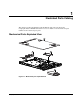
1 Illustrated Parts Catalog This chapter provides the illustrated parts breakdown and spare parts list for the Compaq ProLiant™ DL360 Generation 2 server. See Table 1-1 for the names and part numbers of the referenced spare parts.
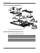
Illustrated Parts Catalog System Components Exploded View 17 15 22 14 16 3 7 6 4 21 5 10 23 8 9 25 27 11 20 12 24 13 26 Figure 1-2: System components exploded view System and Mechanical Spare Parts List Table 1-1: System and Mechanical Spare Parts List Item Description Spare Part Number Mechanical Components 1 Access Panel 252370-001 2 Hard Drive Blank 122759-001 3 PCI Riser Board Assembly 252356-001 continued 1-2 Compaq ProLiant DL360 Generation 2 Server Maintenance and Service G
Illustrated Parts Catalog Table 1-1: System and Mechanical Spare Parts List continued Item Description Spare Part Number System Components 4 Fan Assembly 252360-001 5 Filter, AC Power 252362-001 6 Power Supply 252361-001 Boards 7 System board (without processor; with two heatsinks -Not shown) 252355-001 8 SCSI backplane 173829-001 9 User Interface board 252358-001 10 CD-ROM drive and floppy diskette drive backplane 252357-001 Cable 11 CD-ROM/Diskette backplane to system board cable
Illustrated Parts Catalog Table 1-1: System and Mechanical Spare Parts List continued Item Description Spare Part Number 252368-001 Plastic Kit 22 Air baffle 23 AC power connector cable retaining clip 24 CD ejection mechanism 25 Expansion board clip 26 Front Bezel 27 Power supply retaining clip Return Kit 173842-001 Option Kits (Not Shown) 1-4 Sliding Rails and Cable Management Solution 252366-001 Fixed Rail Kit 252365-001 Telco rack mounting kit 252367-001 AC “Y” power cord 178129
2 Removal and Replacement Procedures This chapter provides subassembly/module-level removal and replacement procedures for Compaq ProLiant DL360 Generation 2 servers. No tools are required to service the server. After completing all necessary removal and replacement procedures, it is recommended that server diagnostic programs be run to verify that all components are operating correctly.
Removal and Replacement Procedures Symbols on Equipment Any product or assembly marked with these symbols indicates that the component exceeds the recommended weight for one individual to handle safely.
Removal and Replacement Procedures Rack Warnings and Precautions WARNING: To reduce the risk of personal injury or damage to equipment, always ensure that the rack is adequately stabilized before extending a component outside the rack. A rack may become unstable if more than one component is extended for any reason. Extend only one component at a time. WARNING: To reduce the risk of personal injury or damage to the equipment, be sure that: • The leveling jacks are extended to the floor.
Removal and Replacement Procedures Preparation Procedures Before removing any serviceable parts, determine whether the part is a hot-plug device or a non-hot-plug device. Hot-Plug Devices The only hot-plug devices on Compaq ProLiant DL360 Generation 2 servers are the SCSI hard drives. SCSI hard drives can be serviced without removing the server from the rack. IMPORTANT: It is not necessary to turn off the server to replace hot-plug hard drives when they are not in active use.
Removal and Replacement Procedures Powering Down the Server System power in servers does not completely shut off with the front panel Power On/Standby switch. The switch toggles between on and standby modes, rather than on and off. The standby position removes power from most electronics and the drives, but portions of the power supply and some internal circuitry remain active. To completely remove all power from the system, disconnect all power cords from the server.
Removal and Replacement Procedures To power down the server: 1. Shut down the server operating system as directed by the operating system instructions. 2. Press the Front Unit Identification LED switch on the server front panel Unit Identification LED switch illuminates. . The Rear 3. Press the server Power On/Standby switch to place the server in standby mode . 1 2 Figure 2-1: Front Unit Identification LED switch and Power On/Standby switch 4.
Removal and Replacement Procedures Removing the Server from the Rack Depending on the rail option deployed on the server, perform one of the following: • For the standard fixed rail deployment, disconnect all the peripherals cables and loosen the thumbscrew that holds the fixed cable tray to the server. Extend and remove the server from the rack. Place the server on a flat level workspace. • For the Sliding Rails and Cable Management Solution, extend the server to its fullest extent from the rack.
Removal and Replacement Procedures Mass Storage Devices The Compaq ProLiant DL360 Generation 2 server supports up to four mass storage devices: • Up to two 1-inch, hot-plug SCSI hard drives • Low-profile CD-ROM drive • Low-profile 3.5-inch, 1.44-MB diskette drive: This section describes the drive cage positions and removal and replacement procedures for these mass storage devices.
Removal and Replacement Procedures CD-ROM Drive The server is delivered with a low-profile diskette drive and a low-profile CD-ROM drive. The CD-ROM and the diskette drive may be removed independently of each other. CAUTION: Do not operate the server without a CD-ROM drive installed. Failure to install a CD-ROM can lead to improper cooling and may damage the system. To remove the CD-ROM drive: 1. Press the Power On/Standby switch to place the server in standby mode. 2.
Removal and Replacement Procedures To replace the CD-ROM drive: 1. Align the CD-ROM with the empty bay and slide the assembly into the chassis until it is fully seated. Figure 2-6: Aligning and installing the CD-ROM drive 2. Press the Power/On Standby switch to power on the server, and resume normal operations.
Removal and Replacement Procedures Low Profile Diskette Drive To remove the diskette (floppy) drive: CAUTION: Do not operate the server without a diskette drive installed. Failure to install a diskette drive can lead to improper cooling and may damage the system. 1. Power down the server. See “Powering Down the Server” in this chapter. 2. Remove the server from the rack. See “Removing the Server from the Rack” in this chapter. 3. Remove the access panel. See “Server Access Panel” in this chapter. 4.
Removal and Replacement Procedures To replace the diskette drive: 1. Insert the diskette drive through the opening in the front panel . 2. Align the connectors on the backplane and the rear of the diskette drive and push them together . 3. Replace the diskette drive locking tab and turn the thumbscrew clockwise to secure the drive . 1 3 2 Figure 2-8: Installing the diskette drive. 4. Replace the access panel. See “Server Access Panel” in this chapter. 5. Replace the server in the rack.
Removal and Replacement Procedures Hot-Plug SCSI Hard Drive Blank CAUTION: Do not operate the server without a SCSI hard drive or a SCSI hard drive blank installed. Failure to install a SCSI hard drive or a SCSI hard drive blank can lead to improper cooling and may damage the system. To remove a hot-plug SCSI hard drive blank: 1. Press the release button . 2. Pull the blank out of the drive bay .
Removal and Replacement Procedures Hot-Plug SCSI Hard Drives To assess a hard drive’s status, you must observe and understand the hot-plug SCSI hard drive status LEDs. For a detailed explanation of hard drive status LEDs, see Chapter 5, “Connectors, Switches, Jumpers and Status LED Indicators.” WARNING: Read “Hot-plug Hard Drive Replacement Guidelines” in the Compaq Servers Troubleshooting Guide prior to removing a hard drive.
Removal and Replacement Procedures To replace the hard drive: 1. 2. . Close the lever to lock the drive in place .
Removal and Replacement Procedures SCSI Backplane To remove the SCSI backplane: 1. Power down the server. See “Powering Down the Server” earlier in this chapter. 2. Remove the server from the rack. See “Removing the Server from the Rack” in this chapter. 3. Remove the access panel. See “Server Access Panel” in this chapter. 4. Remove the hot-plug SCSI hard drives. See “Hot-Plug SCSI Hard Drives” earlier in this chapter. 5.
Removal and Replacement Procedures 6. Carefully pull back and hold the plastic retaining clip . 7. Remove the SCSI backplane by lifting it straight up from system board until it disengages from the system board connector. 2 1 Figure 2-13: Removing the SCSI backplane Reverse steps 1 through 7 to replace the SCSI backplane.
Removal and Replacement Procedures PCI Riser Board Assembly To remove the PCI riser board assembly: 1. Power down the server. See “Powering Down the Server” earlier in this chapter. 2. Remove the server from the rack. See “Removing the Server from the Rack” in this chapter. 3. Remove the access panel. See “Server Access Panel” earlier in this chapter. 4. Disconnect any cables leading from any current expansion boards to the system board. 5. Lift the expansion board retaining lever.
Removal and Replacement Procedures 6. Unlock the PCI riser board assembly by disengaging the locking latch 7. Lift the PCI riser board assembly ejector . . 8. Slide the assembly toward the outside edge of the server to release the assembly from the server chassis . 9. Lift the assembly from the server chassis . 4 3 2 4 1 Figure 2-15: Removing the PCI riser board assembly (expansion boards removed for clarity) Reverse steps 1 through 9 to replace the PCI riser board assembly.
Removal and Replacement Procedures Expansion Board Slot 1 To remove an expansion board from slot 1: 1. Power down the server. See “Powering Down the Server” earlier in this chapter. 2. Remove the server from the rack. See “Removing the Server from the Rack” in this chapter. 3. Remove the access panel. See “Server Access Panel” earlier in this chapter. 4. Remove the PCI riser board assembly. See “PCI Riser Board Assembly” in this chapter. 5. Slide the expansion board retaining clip out from the assembly 6.
Removal and Replacement Procedures Expansion Board Slot 2 To remove an expansion board in slot 2: 1. Power down the server. See “Powering Down the Server” earlier in this chapter. 2. Remove the server from the rack. See “Removing the Server from the Rack” in this chapter. 3. Remove the access panel. See “Server Access Panel” earlier in this chapter. 4. Remove the PCI riser board assembly. See “PCI Riser Board Assembly” earlier in this chapter. 5. Slide the expansion board out of the expansion slot.
Removal and Replacement Procedures Air Baffle To remove the air baffle: 1. Power down the server. See “Powering Down the Server” earlier in this chapter. 2. Remove the server from the rack. See “Removing the Server from the Rack” in this chapter. 3. Remove the access panel. See “Server Access Panel” earlier in this chapter. 4. Remove the PCI riser board assembly. See “PCI Riser Board Assembly” in this chapter. CAUTION: Always remove the PCI riser board assembly before removing the air baffle.
Removal and Replacement Procedures Fan Assembly To remove the fan assembly: 1. Power down the server. See “Powering Down the Server” earlier in this chapter. 2. Remove the server from the rack. See “Removing the Server from the Rack” in this chapter. 3. Remove the access panel. See “Server Access Panel” earlier in this chapter. 4. Remove the PCI riser board assembly. See “PCI Riser Board Assembly” in this chapter. 5. Remove the air baffle. See “Air Baffle” earlier in this chapter. 6.
Removal and Replacement Procedures AC Power Cord and Line Filter To remove the AC power cord and line filter: 1. Power down the server. See “Powering Down the Server” in this chapter. 2. Remove the server from the rack. See “Removing the Server from the Rack” in this chapter. 3. Remove the access panel. See “Server Access Panel” earlier in this chapter. 4. Remove the PCI riser board assembly. See “PCI Riser Board Assembly” in this chapter. 5.
Removal and Replacement Procedures 8. Loosen the retaining clip screw the release latch . , with a screwdriver, and slide the retaining clip clear of 1 2 Figure 2-21: Sliding off the retaining clip 9. Press the release latch and pull the filter to disconnect the power cord and line filter assembly from the server internal power cord . 2 1 2 Figure 2-22: Disconnecting the line filter from the server internal power cord Reverse steps 1 through 9 to replace the AC power cord and filter.
Removal and Replacement Procedures Power Supply To remove the power supply: 1. Power down the server. See “Powering Down the Server” in this chapter. 2. Remove the server from the rack. See “Removing the Server from the Rack” in this chapter. 3. Remove the access panel. See “Server Access Panel” in this chapter. 4. Remove the PCI riser board assembly. See “PCI Riser Board Assembly” in this chapter. 5. Remove the air baffle. See “Air Baffle” in this chapter. 6. Remove the AC power cord and filter.
Removal and Replacement Procedures Cable Protector To remove the cable protector: 1. Complete the preparation procedures. See “Powering Down the Server” in this chapter. 2. Remove the server from the rack. See “Removing the Server from the Rack” in this chapter. 3. Remove the access panel. See “Server Access Panel” in this chapter. 4. Remove the PCI riser board assembly. See “PCI Riser Board Assembly” in this chapter. 5. Remove the air baffle. See “Air Baffle” in this chapter. 6.
Removal and Replacement Procedures CD-ROM and Diskette Drive Cable and Backplane To remove the CD-ROM and diskette drive cable and backplane: 1. Power down the server. See “Powering Down the Server” in this chapter. 2. Remove the server from the rack. See “Removing the server from the Rack” in this chapter. 3. Remove the access panel. See “Server Access Panel” in this chapter. 4. Remove the CD-ROM and diskette drives.
Removal and Replacement Procedures 11. Slide the cable from underneath the routing sleeve routing diagram. . Refer to Chapter 3 for the cable 12. Carefully pull back and hold the plastic retaining clip . 13. Lift the backplane vertically until it disconnects from the user interface board and clears the guiding grooves .
Removal and Replacement Procedures User Interface Board To remove the user interface board: 1. Power down the server. See “Powering Down the Server” in this chapter. 2. Remove the server from the rack. See “Removing the Server from the Rack” in this chapter. 3. Remove the access panel. See “Server Access Panel” in this chapter. 4. Remove the CD-ROM and diskette drives. See “Replacing the CD-ROM Drive” and “Replacing the Floppy Drive” in this chapter for removal procedures. 5.
Removal and Replacement Procedures Memory The ProLiant DL360 Generation 2 server ships standard with two 128-MB Synchronous DRAM (SDRAM) Dual Inline Memory Modules (DIMMs) installed in DIMM sockets 1 and 2 (Bank A). Observe the following guidelines when installing additional memory: • SDRAM DIMMs must be 133-MHz, registered, 3.3-volt, 72-bit wide, with Error Correction Code (ECC). No other DIMMS are compatible with the server. • Use only 128-, 256-, 512-MB, or 1-GB SDRAM DIMMs.
Removal and Replacement Procedures SDRAM DIMMs The Compaq ProLiant DL360 Generation 2 server ships standard with two SDRAM DIMMs installed in DIMM sockets 1 and 2 (Bank A). The following figure and table show the location of the DIMM slots on the system board.
Removal and Replacement Procedures To remove a SDRAM DIMM: 1. Power down the server. See “Powering Down the Server” in this chapter. 2. Remove the server from the rack. See “Removing the Server from the Rack” in this chapter. 3. Remove the access panel. See “Server Access Panel” in this chapter. 4. Press both SDRAM DIMM slot latches outward 5. Lift the SDRAM DIMM from the socket . . 2 1 1 Figure 2-29: Removing an SDRAM DIMM Reverse steps 1 through 5 to replace a SDRAM DIMM.
Removal and Replacement Procedures Processors The server can support up to two processors. Each processor has an associated Processor Power Module (PPM) that must be present for proper operation of the server. Figure 2-30 and Table 2-3 show the location of the processors and PPMs on the system board.
Removal and Replacement Procedures To remove a processor: 1. Power down the server. See “Powering Down the Server” in this chapter. 2. Remove the server from the rack. See “Removing the Server from the Rack” in this chapter. 3. Remove the access panel. See “Server Access Panel” in this chapter. 4. Push down on the integrated heatsink-retaining clip tab on the processor socket . and release it from the retaining 5. Remove the heatsink and integrated thermal pad from the processor .
Removal and Replacement Procedures CAUTION: Always use a new thermal pad and heatsink when replacing processors. Failure to use new components may result in damage to the processor. CAUTION: Heatsinks have an integrated, plastic-covered thermal pad. Remove the plastic cover from the new heatsink to expose the adhesive side of the thermal pad before placing the heatsink on the processor. Reverse steps 1 through 7 to replace the processor.
Removal and Replacement Procedures Processor Power Module Each processor has an associated Processor Power Module (PPM). Figure 2-30 and Table 2-3 show the location of the processors and PPMs on the system board. To remove a PPM: 1. Power down the server. See “Powering Down the Server” in this chapter. 2. Remove the server from the rack. See “Removing the Server from the Rack” in this chapter. 3. Remove the access panel. See “Server Access Panel” in this chapter. . Lift the PPM from the socket . 4.
Removal and Replacement Procedures Battery If the server no longer automatically displays the correct date and time, it may be necessary to replace the battery that provides power to the real-time clock. Under normal use, battery life is 5 to 10 years. WARNING: This server contains either an internal lithium manganese dioxide, or a vanadium pentoxide battery. There is risk of fire and burns if the battery pack is not handled properly.
Removal and Replacement Procedures To remove the system board battery: 1. Power down the server. See “Powering Down the Server” in this chapter. 2. Remove the server from the rack. See “Removing the Server from the Rack” in this chapter. 3. Remove the access panel. See “Server Access Panel” in this chapter. 4. Locate the battery holder on the system board . Figure 2-33: Battery location 5. Push the battery security clip away from the center of the holder battery .
Removal and Replacement Procedures System Board To remove the system board: 1. Power down the server. See “Powering Down the Server” in this chapter. 2. Remove the server from the rack. See “Removing the Server from the Rack” in this chapter. 3. Remove the access panel. See “Server Access Panel” in this chapter. 4. Remove the hot-plug SCSI hard drive(s). See “Hot-Plug SCSI Hard Drives” in this chapter. 5. Remove the SCSI backplane. See “SCSI Backplane” in this chapter. 6.
Removal and Replacement Procedures 16. Slide the system board toward the front of the chassis 0.5 inch (1.5 cm) the board unseats from all the alignment keys. , ensuring that 17. Tilt the front edge of the system board upward and lift it off the alignment keys 1 . 2 Figure 2-36: Removing the system board CAUTION: Always use a new heatsink with integrated thermal pad when replacing processors. Failure to use new components may result in damage to the processor.
3 Cable Routing Diagram The Compaq ProLiant DL360 Generation 2 server contains only one internal cable. CAUTION: When routing cables, always ensure that the cables are not in a position where they will be pinched or crimped. CD-ROM/Diskette Drive Backplane Cabling The following figure identifies the proper routing of the cable leading from the CD-ROM/diskette drive backplane to the system board.
4 Diagnostic Tools This chapter provides an overview of the diagnostic and management tools available for the Compaq Proliant DL360 Generation 2 server. For more detailed information and procedures refer to the Compaq Server Troubleshooting Guide on the Server Documentation CD. Diagnostic Tools Overview The following tools are available to diagnose problems, test hardware, and monitor and manage server operations.
Diagnostic Tools Table 4-1: Diagnostic Tools continued Tool Description How to run the tool Compaq Server Diagnostics Program Utility to assist testing and/or verifying operation of Compaq hardware. If problems are found, Compaq Server Diagnostics isolates failure(s) down to replaceable parts, whenever possible. Access Compaq Server Diagnostics when Power-OnSelf-Test (POST) detects a system configuration error.
Diagnostic Tools Table 4-1: Diagnostic Tools continued Tool Description How to run the tool Integrated Management Log (IML) A log of system events, such as system failures or nonfatal error conditions. View events in the Integrated Management Log from within: The Integrated Management Log requires Compaq operating system-dependent drivers. Refer to Compaq Support Software CD for instructions on installing the appropriate drivers.
5 Connectors, Switches, Security Override Jumper and Status LED Indicators This chapter describes the various connectors, switches, security override jumper, and LED status indicators that are on the Compaq ProLiant Generation 2 server. Connectors This section contains figures and tables showing the connector locations on the rear panel, the PCI riser board assembly and the system board of the server.
Connectors, Switches, Security Override Jumper and Status LED Indicators Rear Panel Connectors Figure 5-1 and Table 5-1 show and describe the connectors on the rear panel of the server.
Connectors, Switches, Security Override Jumper and Status LED Indicators Riser Board Expansion Slots Figure 5-2 and Table 5-2 show and describe the server expansion slots. 1 2 3 4 5 Figure 5-2: Riser board expansion slots Table 5-2: Riser Board Expansion Slots Item Description Slot 1 64-bit/3.3V slot with 528-MB/s data transfer Slot 1 cover Slot 2 cover Slot 2 64-bit/3.
Connectors, Switches, Security Override Jumper and Status LED Indicators System Board Connectors and Sockets Figure 5-3 and Table 5-3 show and describe the system board connectors and sockets.
Connectors, Switches, Security Override Jumper and Status LED Indicators System Board Switches and Security Override Jumper This section indicates and describes the functions of the switches and security override jumper on the server system board for configuration and support purposes. The Compaq ProLiant DL360 Generation 2 server has three switch banks (SW2, SW3 and SW4) and an Integrated Lights-Out (iLO) security override jumper. Figure 5-4 and Table 5-4 identify the switches.
Connectors, Switches, Security Override Jumper and Status LED Indicators System Chassis ID Switch (SW3) Table 5-5 defines the function for each setting on SW3. Table 5-5: Chassis ID (SW3) Switch Settings Switch On/Off Function S1 Off Chassis ID - Reserved for future use S2 Off Chassis ID - Reserved for future use S3 Off Chassis ID - Reserved for future use S4 Off Reserved System Miscellaneous Support Switch (SW4) Table 5-6 defines the function for each setting on SW4.
Connectors, Switches, Security Override Jumper and Status LED Indicators Integrated Lights-Out Security Override Jumper The iLO Security Override allows the administrator full access to the iLO processor. This will be necessary in the event of a lost or forgotten administrator password and also to flash the iLO boot-block. The iLO Security Override is a jumper located inside the server and cannot be activated without removing the server access panel.
Connectors, Switches, Security Override Jumper and Status LED Indicators A warning message will be displayed on the iLO Web pages indicating the iLO Security Override function is currently active. An iLO log entry will be added recording the use of the iLO Security Override. An SNMP alert may also be sent upon setting or clearing the iLO Security Override function. In the unlikely event it is necessary, enabling the iLO Security Override also enables the iLO boot-block to be flashed.
Connectors, Switches, Security Override Jumper and Status LED Indicators Status LED Indicators The Compaq ProLiant DL360 Generation 2 server contains several sets of LED indicators that indicate the status of hardware components and settings.
Connectors, Switches, Security Override Jumper and Status LED Indicators Front Panel Status LED Indicators The front panel contains three LEDs and two illuminated switches to indicate server status. Figure 5-6 and Table 5-7 identify, describe and indicate the status of the LEDs.
Connectors, Switches, Security Override Jumper and Status LED Indicators Rear Panel Status LED Indicators Figure 5-7 and Table 5-8 identify and describe each LED.
Connectors, Switches, Security Override Jumper and Status LED Indicators Hot-Plug SCSI Hard Drive Status LED Indicators Each hot-plug SCSI hard drive has three LED indicators located on the front of the drive. Use Figure 5-8 and Table 5-9 to identify and describe the status of the drive. 1 2 3 Figure 5-8: Hot-plug SCSI hard drive LED indicators 5-12 , where on indicates activity and off • The LED on the left indicates Drive Activity indicates no activity by the drive.
Connectors, Switches, Security Override Jumper and Status LED Indicators Table 5-9: Hot-Plug Hard Drive LED Indicator Status Combinations Activity Online Fault Condition On Off Off Do not remove the drive. Removing a drive during this process will cause data loss. The drive is being accessed and is not configured as part of an array. On Flashing Off Do not remove the drive. Removing a drive during this process will cause data loss. The drive is rebuilding or undergoing capacity expansion.
Connectors, Switches, Security Override Jumper and Status LED Indicators System Board Status LED Indicators Use Figure 5-9 and Table 5-10 to identify the LED locations and status.
Connectors, Switches, Security Override Jumper and Status LED Indicators Table 5-10: System Board LEDs continued Item LED Description Status Riser failure Amber = PCI riser assembly not seated or installed Off = Normal Over-temperature Amber = Temperature has exceeded OS cautionary level or critical hardware level Off = Temperature is OK CPU Fan Failure Amber = Fan Failed Off = Fan OK Processor Power Module (PPM) 2 Amber = PPM2 failed Off = Normal Processor 2 failure Amber = P
Connectors, Switches, Security Override Jumper and Status LED Indicators System Board LEDs and Internal Health LED Status Combinations When the internal health LED on the front panel illuminates either amber or red, the server is experiencing a health event. Combinations of illuminated system LEDs and the internal health LED indicate system status. NOTE: For the internal health LED to provide pre-failure and system conditions, the system management driver must be installed.
Connectors, Switches, Security Override Jumper and Status LED Indicators Table 5-11: System LEDs and Internal Health LED Status Combinations continued System Board LED and Color Internal Health LED Color Status DIMM failure, slot X (Amber) Red • DIMM in slot X has failed. • DIMM in slot X is an unsupported type. • DIMM in slot X has experienced a multibit error. • DIMM in slot X has reached single-bit correctable error threshold. • DIMM in slot X is in a pre-failure condition.
6 Specifications This chapter provides operating and performance specifications for the Compaq ProLiant DL360 Generation 2 server. The sections in this chapter are: • System Unit • Memory • 1.
Specifications System Unit Table 6-1: System Unit Specifications Dimensions Height (without feet) 4.19 cm 1.65 in Depth 65.45 cm 25.75 in Width 42.55 cm 16.75 in Weight (maximum) 11.81 kg 26 lb Weight (no drives installed) 9.54 kg 21 lb Rated input voltage 100 VAC to 240 VAC — Rated input frequency 50 Hz to 60 Hz — Rated input current 2.8 A (110 V) to 1.
Specifications Memory Table 6-2: SDRAM DIMM Specifications Item Decription Size 128 MB, 256 MB, 512 MB, 1GB Speed 133 MHz Width 72 bits Upgrade requirements Identical DIMMs must be installed in pairs in the same bank (A or B) Note: Use only 128-, 256-, 512-MB or 1-GB, 72 bits wide, 3.3-volt, registered ECC SDRAM. SDRAM must be 133 MHz. Use Compaq SDRAM only. Low-Profile 1.44-MB Diskette Drive Table 6-3: Low-Profile 1.44-MB Diskette Drive Specifications Item Description Size 88.9 mm (3.
Specifications Low-Profile IDE CD-ROM Table 6-4: Low-Profile IDE CD-ROM Drive Specification Item Description Applicable disk CD-DA, CD-ROM (mode 1 and 2); CD-XA (mode 2, Form1 and 2), CD-1 Ready; CD-Extra; Photo CD (single and multiple session); CDI ready Capacity 550 MB (mode 1, 12 cm) / 640 MB (mode 2, 12 cm) Block size 2638,2352 bytes (mode 0); 2352, 2340, 2336, 1024 bytes (mode 1); 2352, 2340, 2336, 2048, 1024 bytes (mode 2) Dimensions Height 12.7 mm (0.5 inch) Depth 130 mm (5.
Specifications Wide Ultra3 SCSI Hard Drives Table 6-5: Wide Ultra3 SCSI Hard Drive Specifications Item 9-GB Drive 18-GB Drive 36-GB Drive 72-GB Drive Capacity 9100.0 MB 18,209.8 MB 36,419.6 MB 72,839.2 MB Height One-third, 1.0 in One-third, 1.0 in One-third, 1.0 in One-third, 1.0 in Size 3.5 in 3.5 in 3.5 in 3.
Index A AC power cord and filter removing 2-24 replacing 2-25 access panel removing 2-7 replacing 2-7 ADU, description 4-1 air baffle removing 2-22 replacing 2-22 alignment keys 2-41 ASR, description 4-1 B battery removing 2-39 replacing 2-39 blanks, SCSI hard drive 2-13 C cable protector removing 2-27 replacing 2-27 cable routing diagram 3-1 cabling, CD-ROM/diskette drive backplane to system board 3-1 CD-ROM drive removing 2-9 replacing 2-10 specifications 6-4 CD-ROM/diskette drive backplane removing 2-
Index replacing in slot 1 2-20 replacing in slot 2 2-21 retaining clip 2-20 expansion slots locating 5-3 L fan assembly removing 2-23 replacing 2-23 floppy disk drive See diskette drive front unit identification switch and LED 2-6 LEDs diagnostic 5-14 front panel status 5-10 front unit identification switch 2-6 hot-plug SCSI hard drives 5-12 to 5-13 rear panel status 5-11 rear unit identification switch 2-6 status combinations hot-plug hard drive 5-13 system board and internal health 5-16 system board 5
Index R RBSU description 4-3 rear unit identification LED switch 2-6 release button hard drive 2-14 removing AC power cord and filter 2-24 access panel 2-7 air baffle 2-22 battery 2-39 cable protector 2-27 CD-ROM drive 2-9 CD-ROM/diskette drive backplane 2-28 DIMMs 2-33 diskette drive 2-11 expansion board from slot 1 2-20 expansion board from slot 2 2-21 fan assembly 2-23 hard drive 2-14 memory 2-33 PCI riser board assembly 2-18 power supply 2-26 PPMs 2-37 processors 2-35 SCSI backplane 2-16 SCSI hard driv
Index system components exploded view 1-2 illustrated 1-2 system unit specifications 6-2 T temperature ranges server 6-2 troubleshooting internal health LED status combinations 5-16 utilities ADU, description 4-1 ASR, description 4-1 Compaq Insight Manager, description 4-2 Survey Utility, description 4-2 Survey, installing 4-2 Diagnostics, description 4-2 Inspect accessing 4-2 description 4-2 Integrated Management Log, description 4-3 ROMPaq, description 4-3 U user interface board removing 2-30 replacin