HP ProLiant DL360 Generation 3 Server Maintenance and Service Guide September 2003 (Fourth Edition) Part Number 293948-004
© 2003 Hewlett-Packard Development Company, L.P. Microsoft, Windows, and Windows NT are U.S. registered trademarks of Microsoft Corporation. Hewlett-Packard Company shall not be liable for technical or editorial errors or omissions contained herein. The information in this document is provided “as is” without warranty of any kind and is subject to change without notice. The warranties for HP products are set forth in the express limited warranty statements accompanying such products.
Contents About This Guide Audience Assumptions............................................................................................................................... vii Technician Notes........................................................................................................................................ vii Where to Go for Additional Help.................................................................................................................ix Integrated Management Log ...
Contents Optical Device/Diskette Drive Interface Board .......................................................................................2-28 SCSI Backplane Board ............................................................................................................................2-30 DIMMs.....................................................................................................................................................2-31 Processors ............................................
Contents Chapter 6 Specifications Operating and Performance Specifications for the HP ProLiant DL360 Generation 3 Server .................
About This Guide This maintenance and service guide can be used for reference when servicing HP ProLiant DL360 Generation 3 servers. WARNING: To reduce the risk of personal injury from electric shock and hazardous energy levels, only authorized service technicians should attempt to repair this equipment. Improper repairs can create conditions that are hazardous. Audience Assumptions This guide is for service technicians.
About This Guide CAUTION: To properly ventilate the system, you must provide at least 7.6 cm (3.0 in.) of clearance at the front and back of the server. CAUTION: The computer is designed to be electrically grounded (earthed). To ensure proper operation, plug the AC power cord into a properly grounded AC outlet only. NOTE: Any indications of component replacement or printed wiring board modifications may void any warranty.
About This Guide Where to Go for Additional Help In addition to this guide, the following information sources are available: • User documentation • Service Quick Reference Guide • Service training guides • Service advisories and bulletins • QuickFind information services • Insight Manager software Integrated Management Log The server includes an integrated, nonvolatile management log that contains fault and management information.
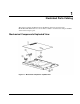
1 Illustrated Parts Catalog This chapter provides the illustrated parts breakdown and spare parts list for the HP ProLiant DL360 Generation 3 server. Refer to Table 1-1 for the names and part numbers of the referenced spare parts.
Illustrated Parts Catalog Table 1-1: Mechanical Components Spare Parts List Item Description Spare Part Number 1 Access panel 307526-001 2 Plastics kit 305451-001 a) Power supply fan baffle b) Left bezel 3 305452-001 Hardware kit a) Power supply blank b) PCI blank System Components Exploded View Figure 1-2: System components exploded view 1-2 HP ProLiant DL360 Generation 3 Server Maintenance and Service Guide
Illustrated Parts Catalog System Components Spare Parts List Table 1-2: System Components Spare Parts List Item Description Spare Part Number 4 System board 305439-001 5 SmartArray 5i plus memory module 260741-001 6 PCI riser board assembly 305442-001 7 DIMM a) 256-MB PC2100 266-MHz DDR SDRAM DIMM 300699-001 b) 512-MB PC2100 266-MHz DDR SDRAM DIMM* 300700-001 c) 1-GB PC2100 266-MHz DDR SDRAM DIMM* 300701-001 d) 2-GB PC2100 266-MHz DDR SDRAM DIMM* 300702-001 8 Processor power module 3
Illustrated Parts Catalog Table 1-2: System Components Spare Parts List continued Item Description Spare Part Number d) 72-GB, 10-K hard drive* 289042-001 e) 72-GB, 15-K hard drive* 289243-001 f) 146-GB, 10K hard drive* 289044-001 20 System fan assembly 307525-001 21 Power converter module 305446-001 22 325-W power supply 305447-001 23 400-W DC power supply* 338887-001 24 System board battery* 234556-001 25 Country kit* 309480-001 26 Return kit* 173842-001 27 Fixed rail kit*
2 Removal and Replacement Procedures This chapter provides subassembly/module-level removal and replacement procedures for the HP ProLiant DL360 Generation 3 server. After completing all necessary removal and replacement procedures, it is recommended that server diagnostic programs be run to verify that all components are operating correctly.
Removal and Replacement Procedures Symbols on Equipment This symbol indicates that the component exceeds the recommended weight for one individual to handle safely. WARNING: To reduce the risk of personal injury or damage to the equipment, observe local occupational health and safety requirements and guidelines for manual material handling. Weight in kg Weight in lb This symbol indicates the presence of a hot surface or hot component. If this surface is contacted, the potential for injury exists.
Removal and Replacement Procedures Rack Warnings and Precautions WARNING: To reduce the risk of personal injury or damage to equipment, always ensure that the rack is adequately stabilized before extending a component outside the rack. A rack may become unstable if more than one component is extended for any reason. Extend only one component at a time. WARNING: To reduce the risk of personal injury or damage to the equipment, be sure that: • The leveling jacks are extended to the floor.
Removal and Replacement Procedures Preparation Procedures Before removing any serviceable parts, determine whether the part is a hot-plug device or a non-hot-plug device. Hot-Plug Devices The hot-plug devices on ProLiant DL360 Generation 3 servers are the U320 SCSI hard drives and power supplies. U320 SCSI hard drives and power supplies can be serviced without removing the server from the rack. IMPORTANT: It is not necessary to turn off the server to replace hot-plug hard drives.
Removal and Replacement Procedures CAUTION: The system power in the server does not completely shut off from the front Power On/Standby switch. Moving the switch from On to Standby leaves some portion of the power supply and some internal circuitry active. Disconnect all power cords from the server to remove all power from the system. CAUTION: Electrostatic discharge may damage electronic components. Be sure you are properly grounded before beginning any installation procedure.
Removal and Replacement Procedures 4. At the rear of the server, locate the illuminated Rear Unit Identification LED switch that identifies the server being serviced. Figure 2-2: Rear Unit Identification LED switch 5. Disconnect power cord(s). Removing the Server from the Rack To remove the server from the rack: 1. If the server has a sliding rail solution: a. Disconnect all remaining cables from the server rear panel (including cables extending from expansion boards). b.
Removal and Replacement Procedures b. Move to the front of the rack and loosen the thumbscrews securing the server to the rack (1). c. Grasp the front panel thumbscrews, and extend the server from the rack. The cables remain clamped in the cable tray. The rail release latches engage automatically. d. Press in and hold the rail release latches (2). e. Extend the server completely out of the rack (3), and set it on a flat, level surface.
Removal and Replacement Procedures To remove the access panel: 1. Lift up on the hood latch (1). The access panel will slide toward the back of the chassis. 2. Lift up to remove the access panel (2). Figure 2-4: Removing the server access panel Reverse steps 1 and 2 to replace the access panel. Processor Fan Module To remove the processor fan module: 1. Power down the server. Refer to “Powering Down the Server” earlier in this chapter. 2. Remove the server from the rack.
Removal and Replacement Procedures 4. Loosen the thumbscrew (1) securing the processor fan module to the chassis. 5. Press the processor fan module from the rear (2) to release it from the system board. Figure 2-5: Loosening the processor fan module thumbscrew 6. Remove the processor fan module from the chassis. Figure 2-6: Removing the processor fan module Reverse steps 1 through 6 to install the processor fan module.
Removal and Replacement Procedures Mass Storage Devices The ProLiant DL360 Generation 3 server can support the following mass storage devices: • (Up to) Two hot-plug U320 SCSI hard drives • A low-profile optical device • A low-profile, 3.5-inch, 1.44-MB diskette drive This section describes the drive cage positions and removal and replacement procedures for these mass storage devices.
Removal and Replacement Procedures Hard Drive Blank CAUTION: Do not operate the server without a hard drive or a hard drive blank installed. Failure to install a hard drive or a hard drive blank can lead to improper cooling and may damage the system. To remove a hard drive blank: 1. Press the release button (1). 2. Pull the blank out of the drive bay (2). Figure 2-8: Removing a hard drive blank To replace the hard drive blank, slide the blank into the bay until it locks into place.
Removal and Replacement Procedures To remove a hot-plug U320 SCSI hard drive: 1. Press the button on the hard drive to release the drive latch (1). 2. Open the drive latch on the hard drive (2). 3. Pull the hard drive to remove it from the server (3). Figure 2-9: Removing a hot-plug U320 SCSI hard drive IMPORTANT: The ProLiant DL360 Generation 3 server supports HP Universal U320 drives only. Compaq branded Ultra3 or HP branded U160 hot-plug drives are not supported.
Removal and Replacement Procedures To replace the hard drive: 1. Slide the hard drive into the open bay (1). 2. Close the drive latch to secure the hard drive into the server (2). Figure 2-10: Installing a hot-plug U320 SCSI hard drive Optical Device The server supports a diskette drive and an optical device. The optical device and the diskette drive may be removed independently. CAUTION: Do not operate the server without an optical device installed.
Removal and Replacement Procedures To remove the optical device: 1. Press the Power On/Standby switch to place the server in standby mode. Refer to “Powering Down the Server” earlier in this chapter. 2. Push the optical device ejector button to release the optical device (1). NOTE: Access to the optical device ejector button is intentionally restricted. Push the optical device ejector button with a small flat object such as a key or pen to eject the optical drive. 3.
Removal and Replacement Procedures To replace the optical device: 1. Align the optical device with the optical device bay and slide the device into the chassis until it is fully seated. Figure 2-12: Aligning and installing the optical device 2. Press the Power/On Standby switch to power on the server, and resume normal operations. Optical Device Ejector To remove the optical device ejector: 1. Power down the server. Refer to “Powering Down the Server” earlier in this chapter. 2.
Removal and Replacement Procedures 5. Remove the screws securing the optical device ejector to the chassis. Figure 2-13: Removing optical device ejector screws 6. Press the tab on the side of the optical device ejector (1) to release it from the chassis. NOTE: Access to the tab on the side of the optical device ejector is restricted. To push in the tab on the optical device ejector, use a small flat object such as a key, screwdriver, or pen. 7.
Removal and Replacement Procedures 8. Press the tab on the side of the optical device ejector (1). 9. Slide the optical device ejector into the slot in the chassis (2) until the tab clicks in to place. Figure 2-15: Inserting the optical device ejector into the chassis 10. Replace the screws securing the optical device ejector to the chassis.
Removal and Replacement Procedures Diskette Drive To remove the diskette drive: CAUTION: Do not operate the server without a diskette drive installed. Failure to install a diskette drive can lead to improper cooling and may damage the system. 1. Power down the server. Refer to “Powering Down the Server” earlier in this chapter. 2. Remove the server from the rack. Refer to “Removing the Server from the Rack” earlier in this chapter. 3. Remove the access panel.
Removal and Replacement Procedures To replace the diskette drive: 1. Slide the diskette drive into the open bay (1). 2. Replace the diskette drive retaining screw (2). Figure 2-18: Installing the diskette drive 3. Replace the hot-plug U320 SCSI hard drive. Refer to “Hot-Plug U320 SCSI Hard Drives” earlier in this chapter. 4. Replace the access panel. Refer to “Server Access Panel” earlier in this chapter. 5. Replace the server in the rack.
Removal and Replacement Procedures 2. If you are removing the power supply from hot-plug power supply bay 1, and there is a sliding rail solution in place: a. Loosen the cable retractor thumbscrew (1). b. Pull the cable retractor back, away from the server chassis, and then away from the rack rail (2). Figure 2-19: Moving the cable retractor to access the power supply in hot-plug power supply bay 1 (cables removed for clarity) 3. Grasp the handle on the power supply. 4.
Removal and Replacement Procedures To install a hot-plug power supply: 1. Remove the protective cover from the connector on the power supply. 2. Slide the power supply into the chassis until it snaps into place. Figure 2-21: Installing a power supply (cables removed for clarity) 3. If you are replacing the power supply from hot-plug power supply bay 1, and there is a sliding rail solution in place: a. Push the cable retractor toward the rack rail and toward the chassis (1). b.
Removal and Replacement Procedures 4. Connect the power cord. PCI Riser Board Assembly The procedures in this section assume that the server is configured with two PCI riser board assemblies. To remove the PCI riser board assembly: 1. Power down the server. Refer to “Powering Down the Server” earlier in this chapter. 2. Remove the server from the rack. Refer to “Removing the Server from the Rack” earlier in this chapter. 3. Remove the access panel. Refer to “Server Access Panel” earlier in this chapter.
Removal and Replacement Procedures 4. Remove the appropriate PCI riser board assembly. Refer to “PCI Riser Board Assembly” earlier in this chapter. 5. Slide the expansion board out of the slot. Figure 2-24: Removing an expansion board from the PCI riser board assembly 6. Align the expansion board with the guiding groove. 7. Slide the expansion board into the slot until the board firmly seats. Figure 2-25: Installing an expansion board into the PCI riser board assembly 8.
Removal and Replacement Procedures I/O System Fan Assembly To remove the I/O system fan assembly: 1. Power down the server. Refer to “Powering Down the Server” earlier in this chapter. 2. Remove the server from the rack. Refer to “Removing the Server from the Rack” earlier in this chapter. 3. Remove the access panel. Refer to “Server Access Panel” earlier in this chapter. 4. Remove the PCI riser board assembly. Refer to “PCI Riser Board Assembly” earlier in this chapter. 5.
Removal and Replacement Procedures 8. Press in the retaining clips on either side of the I/O system fan assembly (1) and lift the assembly from the chassis (2). Figure 2-27: Removing the I/O system fan assembly Reverse steps 1 through 8 to replace the fan assembly. Power Converter Module To remove the power converter module: 1. Power down the server. Refer to “Powering Down the Server” earlier in this chapter. 2. Remove the server from the rack.
Removal and Replacement Procedures 4. If your server is configured with hot-plug power supplies: a. Remove both hot-plug power supplies. Refer to “Hot-Plug Power Supplies” earlier in this chapter. b. Press down on the tab on the power supply fan baffle (1). c. Slide the baffle toward the back of the chassis, and remove it (2). Figure 2-28: Removing the power supply fan baffle 5. If your server is configured with a PCI riser board assembly in PCI expansion board slot 2: a.
Removal and Replacement Procedures 6. Disconnect the optical device/diskette drive interface board power cable (1). 7. Remove the optical device/diskette drive interface board power cable from the clip on the side of the I/O fan assembly (2). Figure 2-29: Disconnecting the optical device/diskette drive interface board power cable 8. Loosen the thumbscrew securing the power converter module to the chassis (1). 9. Slide the power converter module toward the rear of the chassis and remove it (2).
Removal and Replacement Procedures 10. While holding the power converter, disconnect the power supply signal cable and the system power cable from the system board. Figure 2-31: Disconnecting the power supply signal cable and the system power cable from the system board Reverse steps 1 through 10 to replace the power converter module. Optical Device/Diskette Drive Interface Board To remove the optical device/diskette drive interface board: 1. Power down the server.
Removal and Replacement Procedures 5. Disconnect the I/O system fan assembly power cables (1) and the optical device/diskette drive interface board power cable (2). Figure 2-32: Disconnecting I/O system fan assembly and power converter module power cables 6. Disconnect the optical device/diskette drive cable (1). 7. Loosen the thumbscrews securing the interface board to the server chassis (2). 8. Pull the interface board forward, tip it, and remove it from the server chassis (3).
Removal and Replacement Procedures SCSI Backplane Board To remove the SCSI backplane board: 1. Power down the server. Refer to “Powering Down the Server” earlier in this chapter. 2. Remove the server from the rack. Refer to “Removing the Server from the Rack” earlier in this chapter. 3. Remove the access panel. Refer to “Server Access Panel” earlier in this chapter. 4. Remove the optical device/diskette drive interface board. Refer to “Optical Device/Diskette Drive Interface Board” earlier in this chapter.
Removal and Replacement Procedures DIMMs The ProLiant DL360 Generation 3 server ships standard with two Double Data Rate (DDR) Synchronous DRAM (SDRAM) Dual Inline Memory Modules (DIMMs) installed in DIMM sockets 1 and 2 (Bank A). Figure 2-35 and Table 2-2 show the location of the DIMM slots on the system board. Observe the following guidelines when installing additional memory: • DDR SDRAM DIMMs must be 266 MHz, PC2100, 3.3 volts, and 72-bits wide, with Error Correction Code (ECC).
Removal and Replacement Procedures CAUTION: Electrostatic discharge may damage electronic components. Be sure you are properly grounded before beginning any installation procedure. Refer to “Electrostatic Discharge Information” earlier in this chapter. IMPORTANT: A memory module can be installed only one way. Be sure to match the key slots on the module with the tabs on the memory slot. Push the module down into the slot, ensuring that the module is fully inserted and properly seated.
Removal and Replacement Procedures To install a DIMM: 1. Align the key slot in the bottom edge of the DIMM with the tab in the expansion socket. 2. Insert the DIMM at the same angle as the DIMM socket on the system board (1). 3. Press the DIMM firmly until the latches close (2).
Removal and Replacement Procedures Processors This server can support up to two processors. Each processor has an associated processor power module (PPM) that must be present for proper operation of the server.
Removal and Replacement Procedures To remove a processor: 1. Power down the server. Refer to “Powering Down the Server” earlier in this chapter. 2. Remove the server from the rack. Refer to “Removing the Server from the Rack” earlier in this chapter. 3. Remove the access panel. Refer to “Server Access Panel” earlier in this chapter. 4. Unlatch processor heatsink retaining clips (1). 5. Remove the heatsink (2).
Removal and Replacement Procedures 6. Unlatch the socket locking lever (1). 7. Lift the processor from the socket (2). Figure 2-40: Unlocking and removing a processor CAUTION: Always use a new heatsink when replacing processors. Failure to use new components may result in damage to the processor. CAUTION: Make sure the processor locking lever is open before inserting the processor into the processor socket.
Removal and Replacement Procedures To replace the processor: 1. Install the processor into the socket (1). 2. Close the processor locking lever (2). Figure 2-41: Installing and locking a processor in the socket CAUTION: Heatsinks have an integrated, plastic-covered thermal pad. Remove the plastic cover from the new heatsink to expose the adhesive side of the thermal pad before placing the heatsink on the processor. 3. Remove the protective covering from the heatsink.
Removal and Replacement Procedures 4. Install the heatsink (1). CAUTION: Before closing the heatsink retaining clip, be sure the processor socket locking lever is closed. Do not force the lever closed; it should close without resistance. Forcing the lever closed may result in damage to the processor socket, requiring replacement of the system board. 5. Close the processor heatsink retaining clips (2).
Removal and Replacement Procedures 4. Open the PPM locking latches (1). 5. Lift the PPM from the socket (2). Figure 2-44: Removing a processor power module 6. Install a new PPM into the socket (1). 7. Close the locking latches (2). Figure 2-45: Installing a processor power module NOTE: PPMs with the same part number may look different, but they are functionally equivalent.
Removal and Replacement Procedures Battery-Backed Write Cache Enabler 1. Power down the server. Refer to “Powering Down the Server” earlier in this chapter. 2. Remove the server from the rack. Refer to “Removing the Server from the Rack” earlier in this chapter. 3. Remove the access panel. Refer to “Server Access Panel” earlier in this chapter. 4. Remove the PCI riser board assembly from slot 1. Refer to “PCI Riser Board Assembly” earlier in this chapter. 5.
Removal and Replacement Procedures 7. Pull the latch on the BBWC battery module (1). 8. Slide the BBWC battery module toward the front and away from the chassis (2), and remove from the chassis. Figure 2-47: Removing the BBWC battery module from the chassis Reverse steps 1 through 8 to install the BBWC battery module. Battery The ProLiant DL360 Generation 3 server has one memory device that requires a battery for retaining stored information.
Removal and Replacement Procedures To replace a battery: 1. Power down the server. Refer to “Powering Down the Server” earlier in this chapter. 2. Remove the server from the rack. Refer to “Removing the Server from the Rack” earlier in this chapter. 3. Remove the access panel. Refer to “Server Access Panel” earlier in this chapter. 4. Remove the battery-backed write cache enabler battery pack. Refer to “Battery-Backed Write Cache Enabler” earlier in this chapter 5.
Removal and Replacement Procedures 7. Reverse steps 5 and 6 to install a replacement battery. 8. Reverse steps 1 through 3 to complete the installation. 9. Run the ROM-Based Setup Utility to reconfigure the system with the new battery. System Board To replace the system board: 1. Power down the server. Refer to “Powering Down the Server” earlier in this chapter. 2. Remove the server from the rack. Refer to “Removing the Server from the Rack” earlier in this chapter. 3. Remove the access panel.
Removal and Replacement Procedures IMPORTANT: The server serial number must be re-entered through RBSU after replacing the system board. Refer to the “Re-entering the Server Serial Number” section. Re-entering the Server Serial Number After replacing the server I/O module or clearing the NVRAM, the server serial number must be re-entered. To re-enter the serial number: 1. During the server startup sequence, press the F9 key to access RBSU. 2. Select the System Options menu. 3. Select Serial Number.
3 Cable Routing Diagram Server Cable Routing CAUTION: When routing cables, always ensure that the cables are not in a position where they will be pinched or crimped. Figure 3-1 identifies the proper routing of the cables for the HP ProLiant DL360 Generation 3 server.
4 Diagnostic Tools This chapter provides an overview of the diagnostic and management tools available for the HP ProLiant DL360 Generation 3 server. For more detailed information and procedures, refer to the Servers Troubleshooting Guide on the Documentation CD. Diagnostic Tools Overview The following tools are available to diagnose problems, test hardware, and monitor and manage server operations.
Diagnostic Tools Integrated Management Log The Integrated Management Log (IML) records hundreds of events and stores them in an easy-to-view form. The IML timestamps each event with 1-minute granularity.
Diagnostic Tools Option ROM Configuration for Arrays Before installing an operating system, use the Option ROM Configuration for Arrays (ORCA) utility to create the first logical drive, assign RAID levels, and establish online spare configurations.
Diagnostic Tools ROMPaq Utility Flash ROM upgrades the firmware (BIOS) with system or option ROMPaq utilities. To upgrade the BIOS, insert a ROMPaq diskette into the diskette drive and boot the system. The ROMPaq utility checks the system and provides a choice (if more than one exists) of available ROM revisions. This procedure is the same for both system and option ROMPaq utilities. For more information about the ROMPaq utility, refer to www.hp.com.
Diagnostic Tools SmartStart software can: • Install selected server operating systems using packaged product CDs. • Install the latest optimized drivers. • Create and copy standard server configuration scripts using the Scripting Toolkit and Configuration Replication Utility. • Test server hardware using the new Enterprise Diagnostics LX32 Utility. • Update the latest system or option ROM using the ROM Update Utility. • Install software drivers directly from the CD.
5 LEDs, Switches, and Jumpers Status Indicators The HP ProLiant DL360 Generation 3 server contains the following sets of LED indicators, which indicate the status of hardware components and settings: • Front panel LED indicators • Rear panel LED indicators • System board LEDs Use the following sections to determine the location and status of LEDs on the server. Front Panel LED Indicators The set of six LEDs on the front of the server indicates server status.
LEDs, Switches, and Jumpers Table 5-1: Identifying the Front Panel LED Indicators Item LED Status 1 Unit Identification LED/button Blue = Activated Blinking = System remotely managed Off = Deactivated 2 Internal health LED Red = System critical. Refer to system board LEDs to identify component in critical state. Amber = System degraded. Refer to system board LEDs to identify component in degraded state.
LEDs, Switches, and Jumpers Rear Panel LED Indicators The server rear panel contains five LEDs: one for the rear unit identification LED switch, two for the iLO connector, and two for the RJ-45 connectors. Use the following figure and table to identify each LED.
LEDs, Switches, and Jumpers System Board LEDs The system board contains various LEDs, which display current conditions of the server. These are identified in the illustration and table below.
LEDs, Switches, and Jumpers Switches The system board contains three switchbanks that may need to be modified to set configuration or to trigger special functions. These switches can cause problems if they are not correctly set. When adding or removing a component or changing a security feature, the server must be reconfigured to recognize these changes. If the system configuration is incorrect, the server may not work properly, and you may receive error messages on the screen.
LEDs, Switches, and Jumpers System Maintenance Switch (SW2) The system maintenance switch (SW2) is an eight-position switch used for system maintenance. Refer to the labels attached to the inside of the server access panel for the proper system configuration switch settings. The following table shows the shipping configuration of SW2.
LEDs, Switches, and Jumpers Debug LED Switch (SW3) Settings The Debug LED switch (SW3) is a four-position switch used for system maintenance. S1 and S2 function as a pair. The default positions on this switch are Off and Reserved, and they are not modified by the user. Table 5-6 shows the configurations of SW3.
LEDs, Switches, and Jumpers Clearing and Resetting System Configuration Settings It may be necessary at some time to clear and reset system configuration settings. When the system switch position S6 is set to the On position, the system is prepared to erase all system configuration settings from both CMOS and NVRAM. IMPORTANT: Clearing CMOS and/or NVRAM deletes the configuration information.
6 Specifications Operating and Performance Specifications for the HP ProLiant DL360 Generation 3 Server Table 6-1: Operating and Performance Specifications Specifications Dimensions Height 4.32 cm 1.70 in Depth 69.22 cm 27.25 in Width 42.62 cm 16.78 in Weight (maximum) 16.78 kg 37 lb Weight (no drives installed) 12.47 kg 27.5 lb Rated input voltage 100 VAC to 240 VAC — Rated input frequency 50 Hz to 60 Hz — Rated input current 3.8 A (110 V) to 1.
Specifications Table 6-1: Operating and Performance Specifications continued Specifications Power supply output Rated steady-state power 325 W — Maximum peak power 325 W — Operating (Refer to note) 10°C to 35°C 50°F to 95°F Shipping (Refer to note) -40°C to 60°C -40°F to 140°F Temperature range Relative humidity (noncondensing) Operating (Refer to note) 10% to 90% — Nonoperating (Refer to note) 5% to 95% — 28°C 82.
Index A access panel removing 2-8 replacing 2-8 activating unit identification switches 2-5 ASR-2 (Automatic Server Recovery-2) 4-1 B battery location on system board 2-42 part number 2-41 replacing 2-43 battery-backed write cache enabler removing 2-40 replacing 2-41 BIOS upgrade 4-4 blanks hard drive 2-11 PCI 1-2 power supply 1-2 C cable retractor removing 2-20 replacing 2-21 cable routing diagram 3-1 CMOS, clearing 5-8 component-level repairs vii configuration of system 4-3 current, rated input 6-1 re
Index heatsink caution 2-36 removing 2-35 replacing 2-37 help resources ix hot-plug devices, U320 SCSI hard drive 2-4 hot-plug power supplies See power supplies hot-plug U320 SCSI hard drive See hard drive HP authorized reseller ix humidity, server 6-2 I I/O system fan assembly See fan assembly icons, symbols on equipment 2-2 iLO See Integrated lights-Out IML See Integrated Management Log input requirements 6-1 Insight Manager 7 4-1 Integrated Lights-Out (iLO) 4-2 Integrated Management Log (IML) 4-2 K ki
Index R rated input current 6-1 frequency 6-1 power 6-1 voltage 6-1 rear panel, LEDs 5-3 rear unit identification LED switch 2-6 Remote ROM Flash, Smart Components 4-4 removing access panel 2-8 battery 2-42 battery-backed write cache enabler 2-40 DIMMs 2-32 diskette drive 2-18 expansion board in a PCI riser board assembly 2-22 fan assembly 2-24 hard drive 2-12 hard drive blank 2-11 heatsink 2-35 memory 2-32 optical device 2-14 optical device/diskette drive interface board 2-28 PCI riser board assembly 2-22
Index system board battery 2-41 battery replacement 2-42 LEDs 5-4 removing 2-43 replacing 2-44 system components exploded view, illustrated 1-2 T technical support Canada ix other countries ix United States ix technician notes vii telephone numbers ix temperature, server 6-2 Index-4 U unit identification switches LEDs, front 2-5 LEDs, rear 2-5, 5-3 V ventilation clearances viii voltage, rated input 6-1 W warranty viii weight, server 6-1 wet-bulb temperature, server 6-2 HP ProLiant DL360 Generation 3