HP ProLiant DL360 Generation 4p Server Maintenance and Service Guide July 2006 (Third Edition) Part Number 383863-003
© Copyright 2005, 2006 Hewlett-Packard Development Company, L.P. The information contained herein is subject to change without notice. The only warranties for HP products and services are set forth in the express warranty statements accompanying such products and services. Nothing herein should be construed as constituting an additional warranty. HP shall not be liable for technical or editorial errors or omissions contained herein. Microsoft, Windows, and Windows NT are U.S.
Contents Illustrated parts catalog ................................................................................................................. 5 Customer self repair................................................................................................................................... 5 Mechanical components............................................................................................................................. 6 System components .......................................
SmartStart Scripting Toolkit ....................................................................................................................... 38 HP Instant Support Enterprise Edition.......................................................................................................... 39 Option ROM Configuration for Arrays ....................................................................................................... 39 HP ROM-Based Setup Utility ...........................................
Illustrated parts catalog In this section Customer self repair ................................................................................................................................. 5 Mechanical components ........................................................................................................................... 6 System components ..................................................................................................................................
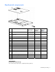
Mechanical components Item Description Original spare part number Modified spare part number Customer self repair (on page 5) 1 Access panel 361400-001 ‡ See requirement 409697-001 Yes 2 Plastics kit 361396-001 ‡ See requirement 409701-001 — a) Optical drive ejector assembly — — Yes b) PCI card guide * — — Yes c) Diskette blank * — — Yes d) Optical device blank * — — Yes Hardware kit 361397-001 — — a) Screws, 6-32X0.25, T-10 (4) * — — Yes b) Screw, 6-32X.
If your unit contains a part that is labelled with the Modified Spare number, the Modified Spare must be ordered as the replacement part in the EU. If your unit contains a part that is labelled with the Original Spare number, please order the Original Spare as the replacement part in the EU. In this case either the Original Spare or the Modified Spare may be shipped which will not affect performance or functionality of the unit.
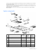
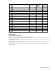
Description Original spare part number Modified spare part number Customer self repair (on page 5) b) Intel® 3.60-GHz Xeon™ 2-MB L2 cache * 381799-001 — Yes c) Intel® 3.80-GHz Xeon™ 2-MB L2 cache 800-MHz FSB * 381798-001 — Yes d) Intel® 3.00-GHz Xeon™ 2-MB L2 cache LV * 397864-001 — Yes e) Intel® 2.80-GHz Xeon™ 2-MB L2 cache * 403625-001 — Yes Batteries — — — a) 3.
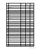
Item 16 Description Original spare part number Modified spare part number Customer self repair (on page 5) a) 36.4-GB 15,000-rpm 289241-001 — Yes b) 72.8-GB 10,000-rpm * 289042-001 — Yes c) 72.8-GB 15,000-rpm * 289243-001 — Yes d) 146.8-GB 10,000-rpm * 289044-001 — Yes SATA hot-plug hard drive — — — a) 80-GB 7.2,000-rpm * 353042-001 — Yes b) 160-GB 7.2,000-rpm * 353043-001 — Yes c) 250-GB 7.
Removal and replacement procedures In this section Required tools........................................................................................................................................ 10 Safety considerations.............................................................................................................................. 10 Preparation procedures...........................................................................................................................
Preventing electrostatic discharge To prevent damaging the system, be aware of the precautions you need to follow when setting up the system or handling parts. A discharge of static electricity from a finger or other conductor may damage system boards or other static-sensitive devices. This type of damage may reduce the life expectancy of the device. To prevent electrostatic damage: • Avoid hand contact by transporting and storing products in static-safe containers.
Power down the server WARNING: To reduce the risk of personal injury, electric shock, or damage to the equipment, remove the power cord to remove power from the server. The front panel Power On/Standby button does not completely shut off system power. Portions of the power supply and some internal circuitry remain active until AC power is removed. IMPORTANT: If installing a hot-plug device, it is not necessary to power down the server. 1. Back up the server data. 2.
a. Press the server rail-release latches and slide the server fully into rack. b. Secure the server by tightening the thumbscrews. 6. Reconnect the peripheral cables and power cords. Removing the server from the rack To remove the server from an HP, Compaq branded, telco, or third-party rack: 1. Power down the server (on page 12). 2. Disconnect all peripheral cables and power cords from the server rear panel. 3. Disconnect the cable management arm, if necessary.
To open the arm: To close the arm: Access panel WARNING: To reduce the risk of personal injury from hot surfaces, allow the drives and the internal system components to cool before touching them. CAUTION: Do not operate the server for long periods with the access panel open or removed. Operating the server in this manner results in improper airflow and improper cooling that can lead to thermal damage. 1. To remove the component: 2.
4. Lift up on the hood latch handle and remove the access panel. To replace the component, reverse the removal procedure. Hard drive blank CAUTION: To prevent improper cooling and thermal damage, do not operate the server unless all bays are populated with either a component or a blank. Remove one of the following: • Remove the SCSI hard drive blank. • Remove the SATA hard drive blank. To replace the blank, slide the blank into the bay until it locks into place.
Hard drive CAUTION: Always power down the server if the boot partition resides on the drive you are replacing or if you are replacing the only drive in the server. CAUTION: To prevent improper cooling and thermal damage, do not operate the server unless all bays are populated with either a component or a blank. 1. Determine the status of the hard drive from the hot-plug hard drive LEDs ("Hot-plug SCSI hard drive LEDs" on page 52). 2. Back up all server data on the hard drive. 3.
To replace the drive, slide the drive into the bay until the latch mechanism engages the server chassis, then close the latch handle to lock the drive in the server chassis. Diskette drive blank 1. Power down the server (on page 12). 2. Extend the server from the rack ("Extending the server from the rack" on page 12). 3. Remove one of the following from the left hard drive bay: • Hard drive blank (on page 15) • Hard drive (on page 16) 4. Use a T-10 Torx screwdriver to remove the locking screw.
5. Remove the diskette drive. To replace the component, reverse the removal procedure. Optical device blank IMPORTANT: The ejector button is recessed to prevent accidental ejection; it may be helpful to use a pen or similar shaped object to access the button. 1. Press the ejector button. 2. Remove the optical device blank. To replace the blank, slide the blank into the bay until it locks into place. Optical device 1. Power down the server (on page 12).
IMPORTANT: The ejector button is recessed to prevent accidental ejection; it may be helpful to use a pen or similar shaped object to access the button. 2. Press the ejector button. 3. Remove the optical device. To replace the drive, slide the drive into the bay until it clicks. Optical device ejector 1. Power down the server (on page 12). 2. Remove all hard drives ("Hard drive" on page 16) and the hard drive blank (on page 15). 3.
8. Remove the optical device ejector. To replace the component, reverse the removal procedure. Hot-plug AC power supply This procedure assumes that the server is configured with two power supplies. CAUTION: To prevent improper cooling and thermal damage, do not operate the server unless all bays are populated with either a component or a blank. 1. 2.
3. Press the power supply release lever, then pull the power supply from the server. To replace the component, reverse the removal procedure. Power supply fan assembly CAUTION: Do not operate the server for long periods with the access panel open or removed. Operating the server in this manner results in improper airflow and improper cooling that can lead to thermal damage. 1. Power down the server (on page 12). 2.
CAUTION: When replacing the component, be sure the power converter module is properly seated in the server chassis. To replace the component, reverse the removal procedure. Processor fan assembly CAUTION: Do not operate the server for long periods with the access panel open or removed. Operating the server in this manner results in improper airflow and improper cooling that can lead to thermal damage. To remove the component: 1.
9. Slide the board toward the front edge of the server, lift up, then slide the board toward the rear of the server to remove the component. To replace the component, reverse the removal procedure. SCSI backplane 1. Power down the server (on page 12). 2. Remove all hot-plug SCSI hard drives ("Hard drive" on page 16). 3. Extend or remove the server from the rack ("Extending the server from the rack" on page 12). 4. Remove the access panel ("Access panel" on page 14). 5.
SATA backplane 1. Power down the server (on page 12). 2. Remove all SATA hard drives ("Hard drive" on page 16). 3. Eject the optical device ("Optical device" on page 18). 4. Extend or remove the server from the rack ("Extending the server from the rack" on page 12). 5. Remove the access panel ("Access panel" on page 14). 6. Remove the optical device and diskette drive interface ("Optical device and diskette drive interface" on page 22). 7. Disconnect all cables connected to the SATA backplane.
c. Lift the front of the assembly slightly and unseat the riser boards from the PCI riser board connectors. To replace the component, reverse the removal procedure. PCI expansion slot definitions Slot Board Size Connector Interconnect PCI-X expansion slot 1 Half-length 133 MHz, 3.3 V 64-bit PCI-X expansion slot 2 Full-length 133 MHz, 3.
2. Remove any expansion board installed in the assembly. To replace the component, reverse the removal procedure. PCI riser board 1. Remove the PCI riser board assembly ("PCI riser board assembly" on page 24). 2. Remove any expansion board installed in the assembly ("PCI-X or PCI Express expansion board" on page 25). 3. Remove the applicable PCI riser boards from the assembly: IMPORTANT: When removing the two parts of the riser board, pay attention to the orientation of the slots on each side.
To replace the component, reverse the removal procedure. Power converter module 1. Power down the server (on page 12). 2. Remove all hot-plug power supplies ("Hot-plug AC power supply" on page 20). 3. Extend or remove the server from the rack ("Extending the server from the rack" on page 12). 4. Remove the access panel ("Access panel" on page 14). 5. Disconnect all internal power cables. 6. Remove the fan module ("Processor fan assembly" on page 22). 7.
Battery-Backed Write Cache Enabler The Battery-Backed Write Cache Enabler, also called the battery pack, works with the cache module to provide transportable data protection, increase overall controller performance, and maintain any cached data for up to 72 hours. The NiMH batteries in the battery pack are continuously recharged through a trickle-charging process whenever the system power is on. Under normal operating conditions, the battery pack lasts for 3 years before replacement is necessary.
8. Lift the battery module from the server. 9. Remove the battery from the module. To replace the component, reverse the removal procedure. Memory options You can expand server memory by installing PC2-3200 DDR2 SDRAM DIMMs. The system supports up to six ECC Registered DDR2 SDRAM DIMMs. NOTE: The Advanced Memory Protection option in RBSU provides additional memory protection beyond Advanced ECC. By default, the server is set to Advanced ECC Support.
DIMM installation guidelines You must observe the following guidelines when installing additional memory: • DIMMs installed in the server must be Registered DDR2 DRAM, 2.5 volts, 64 bits wide, and ECC. • DIMMs in slots 1A and 2A must match and must be installed as a pair. • DIMMs in slots 3B and 4B must match and must be installed as a pair. • DIMMs in slots 5C and 6C must match and must be installed as a pair. • All DIMMs installed must be the same speed.
Processor To remove a processor: 1. Power down the server (on page 12). 2. Extend the server from the rack, if applicable ("Extending the server from the rack" on page 12). 3. Remove the access panel ("Access panel" on page 14). 4. Rotate the baffle upward. 5. Release the processor retaining clips and processor locking lever. 6. Lift the heatsink and processor from the server.
1. Remove the protective cover from the processor. 2. Align the holes in the heatsink with the guiding pegs on the processor cage. CAUTION: To prevent possible server malfunction or damage to the equipment, be sure to align the processor pins with the corresponding holes in the socket.
3. Install the processor and close the processor locking lever and processor retaining clips. 4. Rotate the baffle into position 5. Install the access panel ("Extending the server from the rack" on page 12, "Access panel" on page 14). Battery If the server no longer automatically displays the correct date and time, you may need to replace the battery that provides power to the real-time clock. Under normal use, battery life is 5 to 10 years.
5. Remove the battery. IMPORTANT: Replacing the system board battery resets the system ROM to its default configuration. After replacing the battery, reconfigure the system through RBSU. To replace the component, reverse the removal procedure. For more information about battery replacement or proper disposal, contact an authorized reseller or an authorized service provider. System board 1. Power down the server (on page 12). 2.
10. Remove the system board. IMPORTANT: If replacing the system board or clearing NVRAM, you must re-enter the server serial number through RBSU ("Re-entering the server serial number and product ID" on page 35). To replace the component, reverse the removal procedure. Re-entering the server serial number and product ID After you replace the system board, you must re-enter the server serial number and the product ID. 1. During the server startup sequence, press the F9 key to access RBSU. 2.
Server cabling In this section Cabling overview................................................................................................................................... 36 Server cable routing ............................................................................................................................... 36 SATA cable routing ................................................................................................................................
SATA cable routing CAUTION: When routing cables, always be sure that the cables are not in a position where they can be pinched or crimped.
Diagnostic tools In this section SmartStart software ................................................................................................................................ 38 SmartStart Scripting Toolkit...................................................................................................................... 38 HP Instant Support Enterprise Edition ........................................................................................................
ProLiant BL, ML, and DL servers. The toolkit includes a modular set of utilities and important documentation that describes how to apply these new tools to build an automated server deployment process. Using SmartStart technology, the Scripting Toolkit provides a flexible way to create standard server configuration scripts. These scripts are used to automate many of the manual steps in the server configuration process.
For more information on RBSU, refer to the HP ROM-Based Setup Utility User Guide on the Documentation CD or the HP website (http://www.hp.com/servers/smartstart). ROMPaq utility Flash ROM enables you to upgrade the firmware (BIOS) with system or option ROMPaq utilities. To upgrade the BIOS, insert a ROMPaq diskette into the diskette drive and boot the system. The ROMPaq utility checks the system and provides a choice (if more than one exists) of available ROM revisions.
Integrated Lights-Out technology The iLO subsystem is a standard component of selected ProLiant servers that provides server health and remote server manageability. The iLO subsystem includes an intelligent microprocessor, secure memory, and a dedicated network interface. This design makes iLO independent of the host server and its operating system. The iLO subsystem provides remote access to any authorized network client, sends alerts, and provides other server management functions.
For more information or to download the utility, refer to the HP website (http://www.hp.com/servers/diags). USB support HP provides both standard USB support and legacy USB support. Standard support is provided by the operating system through the appropriate USB device drivers. HP provides support for USB devices before the operating system loads through legacy USB support, which is enabled by default in the system ROM. HP hardware supports USB version 1.1 or 2.0, depending on the version of the hardware.
Server component identification In this section Front panel components .......................................................................................................................... 43 Front panel LEDs and buttons ................................................................................................................... 44 Rear panel components...........................................................................................................................
Item Description 5 Hard drive bay 1 Front panel LEDs and buttons Item Description Status 1 Power On/Standby button and system power LED Green = System is on. Amber = System is shut down, but power is still applied. Off = Power cord is not attached, power supply failure has occurred, no power supplies are installed, facility power is not available, or the DC-to-DC converter is not installed. 2 UID button/LED Blue = Identification is activated. Flashing blue = System is being remotely managed.
Item Description Status 6 NIC 2 link/activity LED Green = Network link exists. Flashing green = Network link and activity exist. Off = No link to network exists. If power is off, the front panel LED is not active. View the LEDs on the RJ-45 connector for status by referring to the rear panel LEDs ("Rear panel LEDs and buttons" on page 46). Rear panel components Item Description 1 PCI-X expansion slot 1, 64-bit/133-MHz 3.
Rear panel LEDs and buttons Item Description Status 1 iLO activity Green = Activity exists. Flashing green = Activity exists. Off = No activity exists. 2 iLO link Green = Link exists. Off = No link exists. 3 10/100/1000 Green = Link exists. NIC 2 activity Flashing green = Activity exists. Off = No link exists. 4 5 6 10/100/1000 Green = Link exists. NIC 2 link Off = No link exists. 10/100/1000 Green = Link exists. NIC 1 link Off = No link exists. 10/100/1000 Green = Activity exists.
System board components Item Description Item Description 1 DIMM slots (1-6) 9 Power supply connector 2 NMI switch 10 Power supply signal connector 3 System maintenance switch (SW2) 11 Smart Array 6i memory module connector* 4 Processor 1 socket 12 Remote management connector 5 Processor 2 socket 13 SATA connectors (SATA model only) 6 Processor zone fan module connector 14 PCI riser board assembly connector (for slot 2 riser board) 7 SCSI backplane connector* 15 PCI riser boa
Position Default Function S5 Off Off = Power-on password is enabled. On = Power-on password is disabled. S6 Off Off = No function On = ROM treats the system configuration as invalid. S7, S8 Off, Off Debug LEDs NMI switch The NMI switch allows administrators to perform a memory dump before performing a hard reset. Crash dump analysis is an essential part of eliminating reliability problems, such as hangs or crashes in operating systems, device drivers, and applications.
Item LED Description Status 4 DIMM 3B failure Amber = DIMM has failed. Off = DIMM is operating normally 5 DIMM 2A failure Amber = DIMM has failed. Off = DIMM is operating normally. 6 DIMM 1A failure 7 Overtemperature Amber = DIMM has failed. Off = DIMM is operating normally Amber = System has reached cautionary or critical temperature level. Off = Temperature is OK. 8 Processor 1 failure .Amber = Processor has failed. Off = Processor is operating normally.
System LED and Color Internal Health LED Color Status Processor failure, socket X (Amber) Red One or more of the following conditions may exist: • Processor in socket X has failed. • Processor in socket X failed over to the offline spare. • Processor X is not installed in the socket. • Processor X is unsupported. • ROM detects a failed processor during POST. Amber Processor in socket X is in a pre-failure condition.
Internal USB connector The front internal USB connector is located in the processor zone fan module. For more information, refer to "Internal USB Functionality (on page 42).
Hot-plug SCSI hard drive LEDs Item LED description Status 1 Activity status On = Drive activity Flashing = High activity on the drive or drive is being configured as part of an array. Off = No drive activity 2 On = Drive is part of an array and is currently working. Online status Flashing = Drive is actively online. Off = Drive is offline.
Activity LED (1) Online LED Fault LED (2) (3) Interpretation On Off Do not remove the drive. Off The drive is being accessed, but (1) it is not configured as part of an array; (2) it is a replacement drive and rebuild has not yet started; or (3) it is spinning up during the POST sequence. Flashing Flashing Flashing Do not remove the drive. Removing a drive may cause data loss in non-fault-tolerant configurations.
Battery-Backed Write Cache Enabler LED statuses Server Status LED Status Battery Module Status Server is on and has normal run time Green = On Fast charging Green = Off Trickle charging Amber = On A short exists in the connection of one or more of the four button cells within the battery module Amber = Blinking An open exists in the circuit between the positive and negative terminals of the battery module Amber = Off Normal Server is on and is in the first 30 Green = On seconds after power up
Processor zone fan module LED Status Amber = One fan in this module has failed. Red = Multiple fans in this module have failed. Off = All fans in this module are operating normally. For power supply zone fan module LED information, refer to "System board LEDs (on page 48).
Specifications In this section Server specifications ............................................................................................................................... 56 Environmental specifications .................................................................................................................... 56 Hot-plug power supply calculations .......................................................................................................... 57 DDR2 SDRAM DIMM specifications....
Specification Value Maximum wet bulb temperature 28°C (82.4°F) Relative humidity (noncondensing)** Operating 10% to 90% Non-operating 5% to 95% * All temperature ratings shown are for sea level. An altitude derating of 1°C per 300 m (1.8°F per 1,000 ft) to 3048 m (10,000 ft) is applicable. No direct sunlight allowed. ** Storage maximum humidity of 95% is based on a maximum temperature of 45°C (113°F). Altitude maximum for storage corresponds to a pressure minimum of 70 KPa.
Specification Value Low 250 Kb/s Bytes/sector 512 Sectors per track (high/low) 18/9 Tracks per side (high/low) 80/80 Access times Track-to-track (high/low) 3 ms/6 ms Average (high/low) 169 ms/94 ms Setting time 15 ms Latency average 100 ms Cylinders (high/low) 80/80 Read/write heads 2 CD-ROM drive specifications Specification Value Disk formats CD-ROM (modes 1 and 2); mixed mode (audio and data combined); CD-DA; Photo CD (single/multiple-session), CD-XA ready; CDi ready Capacity 5
Specification Value Type Semiconductor laser GaAs Wave length 700 ± 25 nm Divergence angle 53.5° ± 1.5° Output power 0.14 mW Operating conditions Temperature 5°C to 45°C (41°F to 118°F) Humidity 5% to 90% DVD-ROM drive specifications Specification Value Disk formats DVD (single and double layer), DVD-5, DVD-9, DVD-10, DVD-R, CD-ROM Mode 1 & 2, CD-DA, CD-XA (Mode 2, Form 1 & 2), CD-I (Mode 2, Form 1 & 2), CD-I ready, CD-Bridge, CD-R, PhotoCD (single and multi-session) Capacity 4.
Specification Value Type Semiconductor laser GaAs Wave length 700 ± 25 nm Divergence angle 53.5° ± 1.5° Output power 0.14 mW Operating conditions Temperature 5°C to 45°C (41°F to 118°F) Humidity 5% to 90% Ultra320 SCSI hard drive specifications Item 36.4-GB Ultra320 SCSI drive 72.8-GB Ultra320 SCSI drive 72.8-GB Ultra320 SCSI drive 146.8-GB Ultra320 SCSI drive Capacity 36,419.6 MB 72,837.2 MB 72,837.2 MB 146,815.74 MB Height 1.0 in (One-third height) 1.0 in (One-third height) 1.
Acronyms and abbreviations ABEND abnormal end ACU Array Configuration Utility ASR Automatic Server Recovery BBWC battery-backed write cache DDR double data rate DU driver update EFS Extended Feature Supplement IEC International Electrotechnical Commission iLO Integrated Lights-Out IML Integrated Management Log IPL initial program load IRQ interrupt request Acronyms and abbreviations 61
MPS multi-processor specification NEMA National Electrical Manufacturers Association NFPA National Fire Protection Association NIC network interface controller NVRAM non-volatile memory ORCA Option ROM Configuration for Arrays PCI Express peripheral component interconnect express PCI-X peripheral component interconnect extended PDU power distribution unit POST Power-On Self Test PPM processor power module PSP ProLiant Support Pack PXE Preboot Execution Environment RBSU ROM-Based Setup Utility
RILOE II Remote Insight Lights-Out Edition II SATA serial ATA SCSI small computer system interface SDRAM synchronous dynamic RAM SIM Systems Insight Manager SIMM single inline memory module SPM system power module SSD support software diskette TMRA recommended ambient operating temperature UID unit identification USB universal serial bus VCA Version Control Agent VHDCI very high density cable interconnect WOL Wake-on LAN Acronyms and abbreviations 63
Index A AC power supply 20 access panel 14 air baffle 11 ASR (Automatic Server Recovery) 41, 61 Automatic Server Recovery (ASR) 41, 61 Autorun menu 38 B battery 28, 33, 47, 48 battery-backed write cache enabler 28 battery-backed write cache enabler LEDs 53, 54 BIOS upgrade 40 blanks 15, 17 blue screen event 48 buttons 43 C cable kits 7 cable management arm 13 cabling 36 CD ejector assembly 19 CD-ROM drive 18, 58 component identification 43, 44, 45, 46, 47, 48, 52 components 43 connectors 43 crash dump ana
K keyboard connector 45 L LEDs 43 LEDs, hard drive 52 M management tools 38 mechanical components 6 memory 29, 30 memory dump 48 memory slot LEDs 48 memory slots 47 mouse connector 45 N network connector LEDs 46 NIC connectors 45 NIC LEDs 43, 44 NMI switch 48 O Online ROM Flash Component Utility 40 online spare memory 29 online spare memory LED 48 operating system crash 48 optical device 18 Option ROM Configuration for Arrays (ORCA) 39 ORCA (Option ROM Configuration for Arrays) 39 overtemperature LED 48
T telco racks 11 temperature, overtemperature LED 48, 52 tools 10, 38 U UID LEDs 12, 43, 44, 45, 46, 48 USB connectors 45 USB support 42 utilities 38 utilities, deployment 38, 39 V VHDCI SCSI connector 45 video connector 45 Index 66