HP ProLiant DL360 Generation 4p Server (SAS Model) Maintenance and Service Guide July 2006 (Fourth Edition) Part Number 391002-004
© Copyright 2005, 2006 Hewlett-Packard Development Company, L.P. The information contained herein is subject to change without notice. The only warranties for HP products and services are set forth in the express warranty statements accompanying such products and services. Nothing herein should be construed as constituting an additional warranty. HP shall not be liable for technical or editorial errors or omissions contained herein. Microsoft, Windows, and Windows NT are U.S.
Contents Illustrated parts catalog ................................................................................................................. 5 Customer self repair................................................................................................................................... 5 Mechanical components............................................................................................................................. 6 System components .......................................
Integrated Management Log ..................................................................................................................... 35 System Online ROM flash component utility ................................................................................................ 35 Integrated Lights-Out technology................................................................................................................ 36 Automatic Server Recovery .................................................
Illustrated parts catalog In this section Customer self repair ................................................................................................................................. 5 Mechanical components ........................................................................................................................... 6 System components ..................................................................................................................................
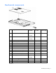
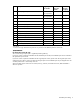
Mechanical components Item Description Original spare part number 1 Access panel 392012-001 ‡ 409697-001 See requirement Yes 2 Plastics kit 392016-001 ‡ 409701-001 See requirement — a) Optical drive ejector assembly — — Yes b) PCI card guide * — — Yes c) Diskette blank * — — Yes d) Optical device blank * — — Yes Hardware kit 361397-001 — — a) Screws, 6-32X0.25, T-10 (4) * — — Yes b) Screw, 6-32X0.187, T-15 (4) * — — Yes c) Screw, M3X0.
‡REQUIREMENT: For Customers in the EU only. The use of the Original Spare part is regulated by RoHS legislation§. If your unit contains a part that is labelled with the Modified Spare number, the Modified Spare must be ordered as the replacement part in the EU. If your unit contains a part that is labelled with the Original Spare number, please order the Original Spare as the replacement part in the EU.
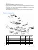
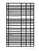
Item Description Original spare part number Modified spare part number Customer self repair (on page 5) 5 Processor/heatsink assembly — — — a) 3.00-GHz Intel® Xeon™ 2-MB L2 cache * 381801-001 — Yes b) 3.20-GHz Intel® Xeon™ 2-MB L2 cache * 382523-001 — Yes c) 3.40-GHz Intel® Xeon™ 2-MB L2 cache * 381800-001 — Yes d) 3.60-GHz Intel® Xeon™ 2-MB L2 cache * 381799-001 — Yes e) 3.80-GHz Intel® Xeon™ 2-MB L2 cache 800-MHz FSB * 381798-001 — Yes f) 3.
Item Description Original spare part number Modified spare part number Customer self repair (on page 5) c) 2-GB (single-rank) * 359243-001 ‡ See requirement 413386-001 Yes d) 2-GB (dual-rank) * 378021-001 ‡ See requirement 413387-001 Yes SAS hard drives — — — a) 36-GB 10,000-rpm * 376596-001 — Yes b) 72-GB 10,000-rpm * 376597-001 — Yes Hard drives 13 Miscellaneous 14 Cable, CD-ROM/diskette * 392015-001 — Yes 15 Cable, SAS * 392014-001 — Yes 16 Cable assembly, SAS, side c
Removal and replacement procedures In this section Required tools........................................................................................................................................ 10 Safety considerations.............................................................................................................................. 10 Preparation procedures...........................................................................................................................
To prevent electrostatic damage: • Avoid hand contact by transporting and storing products in static-safe containers. • Keep electrostatic-sensitive parts in their containers until they arrive at static-free workstations. • Place parts on a grounded surface before removing them from their containers. • Avoid touching pins, leads, or circuitry. • Always be properly grounded when touching a static-sensitive component or assembly.
Power On/Standby button does not completely shut off system power. Portions of the power supply and some internal circuitry remain active until AC power is removed. IMPORTANT: If installing a hot-plug device, it is not necessary to power down the server. 1. Back up the server data. 2. Shut down the operating system as directed by the operating system documentation. 3. If the server is installed in a rack, press the UID LED button on the front panel.
b. Secure the server by tightening the thumbscrews. 6. Reconnect the peripheral cables and power cords. Accessing the product rear panel NOTE: To access some components, you may need to remove the cable management arm. To open the arm: To close the arm: Removing the server from the rack To remove the server from an HP, Compaq branded, telco, or third-party rack: 1. Power down the server ("Powering down the server" on page 11). 2.
4. Loosen the thumbscrews that secure the server faceplate to the front of the rack. 5. Extend the server from the rack ("Extending the server from the rack" on page 12). 6. Disengage the server from the rack. For more information, refer to the documentation that ships with the rack mounting option. 7. Place the server on a sturdy, level surface.
Hard drive CAUTION: Always power down the server if the boot partition resides on the drive you are replacing or if you are replacing the only drive in the server. CAUTION: To prevent improper cooling and thermal damage, do not operate the server unless all bays are populated with either a component or a blank. To remove the component: 1. Determine the status of the hard drive from the hot-plug hard drive LEDs ("Identifying the status of a hard drive" on page 47). 2.
3. Remove the multi-bay blank. To replace the component, reverse the removal procedure. DVD/CD-ROM/diskette drive To remove the component: 1. Power down the server ("Powering down the server" on page 11). IMPORTANT: The ejector button is recessed to prevent accidental ejection; it may be helpful to use a pen or similar shaped object to access the button. 2. Press the ejector button. 3. Remove the multi-bay blank, diskette drive, or multi-bay device.
Multi-bay device ejector To remove the component: 1. Power down the server ("Powering down the server" on page 11). 2. Eject the multi-bay device or multi-bay device blank ("Multi-bay blank or device" on page 15). 3. Extend or remove the server from the rack ("Extending the server from the rack" on page 12). 4. Use a T-10 Torx screwdriver to remove the screws that secure the multi-bay device ejector to the server chassis. 5.
3. Press the power supply release lever, then pull the power supply from the server. To replace the component, reverse the removal procedure. Power supply fan assembly CAUTION: Do not operate the server for long periods with the access panel open or removed. Operating the server in this manner results in improper airflow and improper cooling that can lead to thermal damage. To remove the component: 1. Power down the server ("Powering down the server" on page 11). 2.
CAUTION: When replacing the component, be sure the power converter module is properly seated in the server chassis. To replace the component, reverse the removal procedure. Processor fan assembly CAUTION: Do not operate the server for long periods with the access panel open or removed. Operating the server in this manner results in improper airflow and improper cooling that can lead to thermal damage. To remove the component: 1.
9. Remove the multi-bay release latch screw with a T-15 Torx screwdriver. 10. Remove the multi-bay release latch. 11. Remove the two screws that fasten the multi-bay/SAS backplane to the chassis. 12. Remove the component from the server. To replace the component, reverse the removal procedure. PCI riser board assembly CAUTION: To prevent damage to the server or expansion boards, power down the server and remove all AC power cords before removing or installing the expansion boards.
c. Lift the front of the assembly slightly and unseat the riser boards from the PCI riser board connectors. To replace the component, reverse the removal procedure. PCI expansion slot definitions Slot* Board Size Connector Interconnect PCI-X expansion slot 1 Half-length 133 MHz, 3.3 V 64-bit PCI-X expansion slot 2 Full-length 133 MHz, 3.
5. Remove any expansion board installed in the assembly. To replace the component, reverse the removal procedure. PCI riser board To remove the component: 1. Power down the server ("Powering down the server" on page 11). 2. Extend the server from the rack, if applicable ("Extending the server from the rack" on page 12). 3. Remove the access panel ("Access panel" on page 14). 4. Remove the PCI riser board assembly ("PCI riser board assembly" on page 20). 5.
a. Remove the riser board with the slot for full-length expansion boards. b. Repeat the previous step for the riser board with the slot for half-length expansion boards, if needed. To replace the component, reverse the removal procedure. Power converter module To remove the component: 1. Power down the server ("Powering down the server" on page 11). 2. Remove all hot-plug power supplies ("Hot-plug AC power supply" on page 17). 3.
7. Slide the power converter module toward the back of the server, then lift the power converter module from the server. NOTE: Cables are removed for clarity. To replace the component, reverse the removal procedure. Memory options You can expand server memory by installing PC2-3200 DDR2 SDRAM DIMMs. The system supports up to six ECC Registered DDR2 SDRAM DIMMs. NOTE: The Advanced Memory Protection option in RBSU provides additional memory protection beyond Advanced ECC.
• All DIMMs installed must be the same speed. Do not install DIMM modules supporting different speeds. • Install DIMMs into both slots within a single bank. DIMMs must be installed in order. Upgrade memory by installing DIMM pairs into banks in sequential bank order, starting with bank B. Single- and dual-rank DIMMs PC2-3200 DIMMs can either be single- or dual-rank.
To replace a DIMM, align the DIMM with the slot and insert the DIMM firmly. When fully seated, the DIMM slot latches lock into place. Processor To remove a processor: 1. Power down the server ("Powering down the server" on page 11). 2. Extend the server from the rack, if applicable ("Extending the server from the rack" on page 12). 3. Remove the access panel ("Access panel" on page 14). 4. Rotate the baffle upward. 5. Release the processor retaining clips and processor locking lever. 6.
CAUTION: To prevent possible server malfunction and damage to the equipment, do not mix single- and dual-core processors or processors with different speeds or cache sizes. 1. Remove the protective cover from the processor. 2. Align the holes in the heatsink with the guiding pegs on the processor cage. CAUTION: To prevent possible server malfunction or damage to the equipment, be sure to align the processor pins with the corresponding holes in the socket.
3. Install the processor and close the processor locking lever and processor retaining clips. 4. Rotate the baffle into position. 5. Install the access panel ("Access panel" on page 14). Battery If the server no longer automatically displays the correct date and time, you may need to replace the battery that provides power to the real-time clock. Under normal use, battery life is 5 to 10 years.
5. Remove the battery. IMPORTANT: Replacing the system board battery resets the system ROM to its default configuration. After replacing the battery, reconfigure the system through RBSU. To replace the component, reverse the removal procedure. For more information about battery replacement or proper disposal, contact an authorized reseller or an authorized service provider. System board To remove the component: 1. Power down the server ("Powering down the server" on page 11). 2.
9. Remove the system board. IMPORTANT: If replacing the system board or clearing NVRAM, you must re-enter the server serial number through RBSU. To replace the component, reverse the removal procedure. Re-entering the server serial number and product ID After you replace the system board, you must re-enter the server serial number and the product ID. 1. During the server startup sequence, press the F9 key to access RBSU. 2. Select the Advanced Options menu. 3. Select Serial Number.
Server cabling In this section Cabling overview................................................................................................................................... 31 Server cable routing ............................................................................................................................... 31 Server cable routing for SAS HBA ............................................................................................................
Server cable routing for SAS HBA CAUTION: When routing cables, always be sure that the cables are not in a position where they can be pinched or crimped.
Diagnostic tools In this section SmartStart software ................................................................................................................................ 33 SmartStart Scripting Toolkit...................................................................................................................... 33 HP Instant Support Enterprise Edition ........................................................................................................
ProLiant BL, ML, and DL servers. The toolkit includes a modular set of utilities and important documentation that describes how to apply these new tools to build an automated server deployment process. Using SmartStart technology, the Scripting Toolkit provides a flexible way to create standard server configuration scripts. These scripts are used to automate many of the manual steps in the server configuration process.
For more information on RBSU, refer to the HP ROM-Based Setup Utility User Guide on the Documentation CD or the HP website (http://www.hp.com/servers/smartstart). ROMPaq utility Flash ROM enables you to upgrade the firmware (BIOS) with system or option ROMPaq utilities. To upgrade the BIOS, insert a ROMPaq diskette into the diskette drive and boot the system. The ROMPaq utility checks the system and provides a choice (if more than one exists) of available ROM revisions.
Integrated Lights-Out technology The iLO subsystem is a standard component of selected ProLiant servers that provides server health and remote server manageability. The iLO subsystem includes an intelligent microprocessor, secure memory, and a dedicated network interface. This design makes iLO independent of the host server and its operating system. The iLO subsystem provides remote access to any authorized network client, sends alerts, and provides other server management functions.
For more information or to download the utility, refer to the HP website (http://www.hp.com/servers/diags). USB support HP provides both standard USB support and legacy USB support. Standard support is provided by the operating system through the appropriate USB device drivers. HP provides support for USB devices before the operating system loads through legacy USB support, which is enabled by default in the system ROM. HP hardware supports USB version 1.1 or 2.0, depending on the version of the hardware.
Server component identification In this section Front panel LEDs and buttons ................................................................................................................... 38 Front panel components .......................................................................................................................... 39 Rear panel components...........................................................................................................................
Item Description Status 2 UID button/LED Blue = Identification is activated. Flashing blue = System is being remotely managed. Off = Identification is deactivated. 3 Internal health LED Green = System health is normal. Amber = System is degraded. To identify the component in a degraded state, refer to "System board LEDs (on page 43)." Red = System critical. To identify the component in a critical state, refer to "System board LEDs (on page 43)." Off = System health is normal (when in standby mode).
Item Description 1 Hard drive bay 1 2 Multi-bay (DVD/CD/Diskette) drive 3 Power On/Standby button and system power LED 4 Front USB port 5 Hard drive bay 4 6 Hard drive bay 3 7 Hard drive bay 2 Rear panel components Item Description 1* PCI-X expansion slot 1, 64-bit/133-MHz 3.3V (optional PCI Express slot 1, x8) 2* PCI-X expansion slot 2, 64-bit/133-MHz 3.
Rear panel LEDs and buttons Item Description Status 1 iLO activity Green = Activity exists. Flashing green = Activity exists. Off = No activity exists. 2 iLO link Green = Link exists. Off = No link exists. 3 10/100/1000 Green = Link exists. NIC 2 activity Flashing green = Activity exists. Off = No link exists. 4 5 6 10/100/1000 Green = Link exists. NIC 2 link Off = No link exists. 10/100/1000 Green = Link exists. NIC 1 link Off = No link exists. 10/100/1000 Green = Activity exists.
System board components Item Description 1 DIMM slots (1-6) 2 NMI switch 3 System maintenance switch (SW2) 4 Processor socket 1 5 Processor socket 2 6 Processor zone fan module connector 7 Optical device/multi-bay connector 8 Power supply connector 9 Power supply signal connector 10 Remote management connector 11 PCI riser board assembly connector (for slot 2 riser board) 12 PCI riser board assembly connector (for slot 1 riser board) 13 System battery System maintenance switch P
Position Default Function S5 Off Off = Power-on password is enabled. On = Power-on password is disabled. S6 Off Off = No function On = ROM treats the system configuration as invalid. S7, S8 Off, Off Debug LEDs NMI switch The NMI switch allows administrators to perform a memory dump before performing a hard reset. Crash dump analysis is an essential part of eliminating reliability problems, such as hangs or crashes in operating systems, device drivers, and applications.
Item LED description Status 4 DIMM 3B failure Amber = DIMM has failed. Off = DIMM is operating normally 5 DIMM 2A failure Amber = DIMM has failed. Off = DIMM is operating normally. 6 DIMM 1A failure 7 Overtemperature Amber = DIMM has failed. Off = DIMM is operating normally Amber = System has reached cautionary or critical temperature level. Off = Temperature is OK. 8 Processor 1 failure Amber = Processor has failed. Off = Processor is operating normally.
System LED and color Internal Health LED color Processor failure, socket X Red (amber) Status One or more of the following conditions may exist: • Processor in socket X has failed. • Processor in socket X failed over to the offline spare. • Processor X is not installed in the socket. • Processor X is unsupported. • ROM detects a failed processor during POST. Amber Processor in socket X is in a pre-failure condition. Processor failure, both sockets (amber) Red Processor types are mismatched.
Internal USB connector The front internal USB connector is located in the processor zone fan module. Item Description 1 USB connector 2 Front internal/external selector switch For more information, refer to "Internal USB functionality (on page 37).
Identifying the status of a hard drive When a drive is configured as a part of an array and connected to a powered-up controller, the condition of the drive can be determined from the illumination pattern of the hard drive status lights (LEDs).
1 - Fault/UID LED (amber/blue) 2 - Online/Activity LED (green) Interpretation Off Flashing The drive is active, and it is operating normally. Amber Off A critical fault condition has been identified for this drive, and the controller has placed it offline. Replace the drive as soon as possible. Flashing amber Flashing A predictive failure alert has been received for this drive. Replace the drive as soon as possible. Off Off The drive is offline, a spare, or not configured as part of an array.
Processor zone fan module LED Status Amber = One fan in this module has failed. Red = Multiple fans in this module have failed. Off = All fans in this module are operating normally. For power supply zone fan module LED information, refer to "System board LEDs (on page 43).
Specifications In this section Server specifications ............................................................................................................................... 50 Environmental specifications .................................................................................................................... 50 Hot-plug power supply calculations .......................................................................................................... 51 DDR2 SDRAM DIMM specifications....
Specification Value Maximum wet bulb temperature 28°C (82.4°F) Relative humidity (noncondensing)** Operating 10% to 90% Non-operating 5% to 95% * All temperature ratings shown are for sea level. An altitude derating of 1°C per 300 m (1.8°F per 1,000 ft) to 3048 m (10,000 ft) is applicable. No direct sunlight allowed. ** Storage maximum humidity of 95% is based on a maximum temperature of 45°C (113°F). Altitude maximum for storage corresponds to a pressure minimum of 70 KPa.
Specification Value Low 250 Kb/s Bytes/sector 512 Sectors per track (high/low) 18/9 Tracks per side (high/low) 80/80 Access times Track-to-track (high/low) 3 ms/6 ms Average (high/low) 169 ms/94 ms Setting time 15 ms Latency average 100 ms Cylinders (high/low) 80/80 Read/write heads 2 CD-ROM drive specifications Specification Value Disk formats CD-ROM (modes 1 and 2); mixed mode (audio and data combined); CD-DA; Photo CD (single/multiple-session), CD-XA ready; CDi ready Capacity 5
Specification Value Type Semiconductor laser GaAs Wave length 700 ± 25 nm Divergence angle 53.5° ± 1.5° Output power 0.14 mW Operating conditions Temperature 5°C to 45°C (41°F to 118°F) Humidity 5% to 90% DVD-ROM drive specifications Specification Value Disk formats DVD (single and double layer), DVD-5, DVD-9, DVD-10, DVD-R, CD-ROM Mode 1 & 2, CD-DA, CD-XA (Mode 2, Form 1 & 2), CD-I (Mode 2, Form 1 & 2), CD-I ready, CD-Bridge, CD-R, PhotoCD (single and multi-session) Capacity 4.
Specification Value Type Semiconductor laser GaAs Wave length 700 ± 25 nm Divergence angle 53.5° ± 1.5° Output power 0.14 mW Operating conditions Temperature 5°C to 45°C (41°F to 118°F) Humidity 5% to 90% SAS and SATA hard drive specifications Item 36-GB SAS drive 72-GB SAS drive 60-GB SATA drive Capacity 36,420 MB 73,408 MB 60,022 MB Height 15 mm 15 mm 9 mm Interface SAS SAS Serial ATA Transfer rate 3 GB/sec 3 GB/sec 1.
Acronyms and abbreviations ABEND abnormal end ASR Automatic Server Recovery DDR double data rate iLO Integrated Lights-Out IML Integrated Management Log NIC network interface controller NVRAM non-volatile memory ORCA Option ROM Configuration for Arrays PCI Express peripheral component interconnect express PCI-X peripheral component interconnect extended POST Power-On Self Test PPM processor power module Acronyms and abbreviations 55
RBSU ROM-Based Setup Utility SAS serial attached SCSI SDRAM synchronous dynamic RAM SIM Systems Insight Manager UID unit identification USB universal serial bus Acronyms and abbreviations 56
Index A access panel 14 air baffle 11 ASR (Automatic Server Recovery) 36, 55 Automatic Server Recovery (ASR) 36, 55 Autorun menu 33 B battery 42, 43 BIOS upgrade 35 blanks 14, 15 blue screen event 43 buttons 38 C cable management arm 13 cabling 31 CD-ROM drive 16, 52 component identification 38, 39, 40, 41, 42, 43 components 38 connectors 38 crash dump analysis 43 CSR (customer self repair) 5 customer self repair (CSR) 5 D DC power supply 42 diagnostic tools 33, 35, 36 diagnostics utility 36 DIMM slot LE
M management tools 33 mechanical components 6 memory 24 memory dump 43 memory slot LEDs 43 memory slots 42 mouse connector 40 remote support and analysis tools 34 removal and replacement procedures 10 required tools 10 resetting the system 43 riser interlock LED 43 RJ-45 network connector LEDs 41 ROM, updating 35 ROM-Based Setup Utility (RBSU) 34 ROMPaq utility 35 N S network connector LEDs 41 NIC connectors 40 NIC LEDs 38, 39 NMI switch 43 safety considerations 10 SAS device numbers 46 SATA connectors
V VHDCI SCSI connector 40 video connector 40 Index 59