HP Proliant DL360 G6 Carrier-Grade Server Read Before Install Carrier-Grade Instructions HP Part Number: COOPE-RRTF1 Published: September 2010 Edition: 1
© Copyright 2010 Hewlett-Packard Development Company, L.P. The information contained herein is subject to change without notice. The only warranties for HP products and services are set forth in the express warranty statements accompanying such products and services. Nothing herein should be construed as constituting an additional warranty. HP shall not be liable for technical or editorial errors or omissions contained herein. NEBS™ is a trademark of Telecordia Technologies Incorporated.
1 Converting to Carrier-grade The conversion to carrier-grade consists of the following action: • Changing the settings of the system maintenance switch Preventing Electrostatic Discharge To prevent damage to the system, you must take precautions when setting up the system or the handling of parts. A discharge of static electricity from a finger or other conductor might damage system boards or other static sensitive devices. This type of damage can reduce the life expectancy of the device.
2 Cabling Cable Information This section provides cabling information for installing the HP Proliant DL360 G6 Carrier-Grade Server. NEBS Chassis Ground This carrier-grade product is intended for use in both common bonding networks and isolated bonding networks. Network Cabling Intra-building connections of the HP Proliant DL-series Carrier-Grade Servers require the use of shielded cables grounded at both ends.
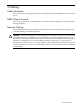
3 Power Supplies Specifications and Cable Information Table 3-1 Power Supplies Specifications Description Value HP 1200W PSU 48VDC Input Part Number 437573–B21 Input Voltage Range (DCV) 36–72 Frequency Range (Nominal) (Hz) Nominal Input Voltage (VDC) DC 36 48 72 1200 1200 1200 38 28 19 Maximum Rated Input Wattage Rating (Watts) 1380 1350 1365 Maximum Rated VA (Volt-Amp) 1380 1350 1365 Efficiency (%) of Maximum Rated Output Wattage 87 89 88 Power Factor n/a n/a n/a Leakage Cur
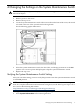
4 Changing the Settings on the System Maintenance Switch WARNING! To prevent personal injury from hazardous energy, remove watches, rings, or other metal objects. 1. 2. 3. 4. Power off the server. Remove power to the server. Remove the top cover. Locate the system maintenance switch. When viewed from the front of the server, the switch is located at the rear of the system board on the right side. See the following graphic illustration: 5. 6.
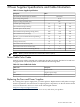
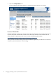
3. Select the Temperatures tab. If the temperature thresholds appear as shown below, the switch is set correctly. Incorrect Thresholds If the thresholds do not show up correctly, ensure the #10 position was set correctly. If incorrectly set, reset the system maintenance switch SW1 to the factory defaults as described in the HP Proliant DL360 G6 Maintenance and Service Guide at the following HP website: http://h20000.www2.hp.com/bizsupport/TechSupport/Home.
5 Installing the DL360 Server into a Seismic Rack For information on the installation of the DL360 Server using a commercial rack mount kit, see the following HP website: http://www.hp.com/support/manuals While not specifically designed for use in seismic rack solutions, the commercial kit was successfully evaluated without modification in the AH343A HP Seismic Rack to the NEBS Zone 4 criteria as part of the DL360 Server NEBS certification.