HP ProLiant DL360 G6 Server Maintenance and Service Guide Abstract This guide is for an experienced service technician. HP assumes you are qualified in the servicing of computer equipment and trained in recognizing hazards in products with hazardous energy levels and are familiar with weight and stability precautions for rack installations.
© Copyright 2009, 2013 Hewlett-Packard Development Company, L.P. The information contained herein is subject to change without notice. The only warranties for HP products and services are set forth in the express warranty statements accompanying such products and services. Nothing herein should be construed as constituting an additional warranty. HP shall not be liable for technical or editorial errors or omissions contained herein. Microsoft® and Windows® are U.S.
Contents Customer self repair ...................................................................................................................... 5 Parts only warranty service ......................................................................................................................... 5 Illustrated parts catalog ............................................................................................................... 15 Mechanical components..............................................
Troubleshooting resources ........................................................................................................................ 60 HP Insight Diagnostics .............................................................................................................................. 60 HP Insight Diagnostics survey functionality .................................................................................................. 60 Integrated Management Log .....................................
Customer self repair HP products are designed with many Customer Self Repair (CSR) parts to minimize repair time and allow for greater flexibility in performing defective parts replacement. If during the diagnosis period HP (or HP service providers or service partners) identifies that the repair can be accomplished by the use of a CSR part, HP will ship that part directly to you for replacement. There are two categories of CSR parts: • Mandatory—Parts for which customer self repair is mandatory.
Obligatoire - Pièces pour lesquelles la réparation par le client est obligatoire. Si vous demandez à HP de remplacer ces pièces, les coûts de déplacement et main d'œuvre du service vous seront facturés. Facultatif - Pièces pour lesquelles la réparation par le client est facultative. Ces pièces sont également conçues pour permettre au client d'effectuer lui-même la réparation.
In base alla disponibilità e alla località geografica, le parti CSR vengono spedite con consegna entro il giorno lavorativo seguente. La consegna nel giorno stesso o entro quattro ore è offerta con un supplemento di costo solo in alcune zone. In caso di necessità si può richiedere l'assistenza telefonica di un addetto del centro di supporto tecnico HP. Nel materiale fornito con una parte di ricambio CSR, HP specifica se il cliente deve restituire dei componenti.
defekte Teil nicht zurückschicken, kann HP Ihnen das Ersatzteil in Rechnung stellen. Im Falle von Customer Self Repair kommt HP für alle Kosten für die Lieferung und Rücksendung auf und bestimmt den Kurier-/Frachtdienst. Weitere Informationen über das HP Customer Self Repair Programm erhalten Sie von Ihrem Servicepartner vor Ort. Informationen über das CSR-Programm in Nordamerika finden Sie auf der HP Website unter (http://www.hp.com/go/selfrepair).
enviara el componente defectuoso requerido, HP podrá cobrarle por el de sustitución. En el caso de todas sustituciones que lleve a cabo el cliente, HP se hará cargo de todos los gastos de envío y devolución de componentes y escogerá la empresa de transporte que se utilice para dicho servicio. Para obtener más información acerca del programa de Reparaciones del propio cliente de HP, póngase en contacto con su proveedor de servicios local.
Neem contact op met een Service Partner voor meer informatie over het Customer Self Repair programma van HP. Informatie over Service Partners vindt u op de HP website (http://www.hp.com/go/selfrepair). Garantieservice "Parts Only" Het is mogelijk dat de HP garantie alleen de garantieservice "Parts Only" omvat. Volgens de bepalingen van de Parts Only garantieservice zal HP kosteloos vervangende onderdelen ter beschikking stellen.
No caso desse serviço, a substituição de peças CSR é obrigatória. Se desejar que a HP substitua essas peças, serão cobradas as despesas de transporte e mão-de-obra do serviço.
Customer self repair 12
Customer self repair 13
Customer self repair 14
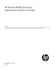
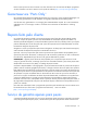
Illustrated parts catalog Mechanical components Item Description Spare part number Customer self repair (on page 5) 1 Access panel 532146-001 Mandatory1 2 Hardware and plastics kit 532392-001 Mandatory1 a) Air baffle — — b) Power supply blank — — c) Fan blank — — d) Dual bezel blank — — e) Hard drive bezel blank (2) — — 3 Hard drive blank* 392613-001 Mandatory1 4 Hard drive cage* 532391-001 Mandatory1 Rack mounting hardware Illustrated parts catalog 15
Item Description Spare part number Customer self repair (on page 5) 5 Rack mounting hardware kit* 533877-001 Mandatory1 6 Cable management arm* 360105-001 Mandatory1 *Not shown 1 Mandatory—Parts for which customer self repair is mandatory. If you request HP to replace these parts, you will be charged for the travel and labor costs of this service. 2 Optional—Parts for which customer self repair is optional. These parts are also designed for customer self repair.
Optional: Optioneel—Onderdelen waarvoor reparatie door de klant optioneel is. Ook deze onderdelen zijn ontworpen voor reparatie door de klant. Als u echter HP verzoekt deze onderdelen voor u te vervangen, kunnen daarvoor extra kosten in rekening worden gebracht, afhankelijk van het type garantieservice voor het product. 3 No: Nee—Sommige HP onderdelen zijn niet ontwikkeld voor reparatie door de klant.
System components Item Description Spare part number Customer self repair (on page 5) 7 Fan module 532149-001 Mandatory1 8 Hot-plug power supplies — — a) 460 W 511804-001 Mandatory1 b) 750 W* 511778-001 Mandatory1 c) 1200 W* 498152-001 Mandatory1 9 PCI riser board assembly (full height PCI-E x16 and half height x8) 493802-001 Mandatory1 10 Processor — — a) 1.86-GHz Intel Xeon processor E5502† 490075-001 Optional2 b) 2.
Item 11 Description Spare part number Customer self repair (on page 5) i) 2.67-GHz Intel Xeon processor X5550*† 490070-001 Optional2 j) 2.80-GHz Intel Xeon processor X5560*† 490069-001 Optional2 k) 2.93-GHz Intel Xeon processor X5570*† 506012-001 Optional2 l) 2.
Item Description Spare part number Customer self repair (on page 5) e) 146-GB, SAS, 10,000-rpm, 6G* 507283-001 Mandatory1 f) 146-GB, SAS, 15,000-rpm* 504334-001 Mandatory1 g) 300-GB, SAS, 10,000-rpm* 493083-001 Mandatory1 h) 300-GB, SAS, 10,000-rpm, 6G* 507284-001 Mandatory1 i) 120-GB, SATA, 5,400-rpm* 459322-001 Mandatory1 j) 250-GB, SATA, 5,400-rpm* 460426-001 Mandatory1 k) 500-GB, SATA, 7,200-rpm* 508035-001 Mandatory1 Options PCI riser board options — — a) PCI-X riser board,
No: Non—Certaines pièces HP ne sont pas conçues pour permettre au client d'effectuer lui-même la réparation. Pour que la garantie puisse s'appliquer, HP exige que le remplacement de la pièce soit effectué par un Mainteneur Agréé. Ces pièces sont identifiées par la mention “Non” dans le Catalogue illustré. 3 Mandatory: Obbligatorie—Parti che devono essere necessariamente riparate dal cliente.
Illustrated parts catalog 22
Removal and replacement procedures Required tools You need the following items for some procedures: • T-10/T-15 Torx screwdriver (on page 76) (provided inside the server) • HP Insight Diagnostics software ("HP Insight Diagnostics" on page 60) Preparation procedures To access some components and perform certain service procedures, you must perform one or more of the following procedures: • Extend the server from the rack (on page 24).
5. If the server is installed in a rack, locate the server by identifying the illuminated rear UID LED button. 6. Disconnect the power cords. The system is now without power. Extend the server from the rack NOTE: If the optional cable management arm option is installed, you can extend the server without powering down the server or disconnecting peripheral cables and power cords. These steps are only necessary with the standard cable management solution. 1. Power down the server (on page 23). 2.
• Avoid hand contact by transporting and storing products in static-safe containers. • Keep electrostatic-sensitive parts in their containers until they arrive at static-free workstations. • Place parts on a grounded surface before removing them from their containers. • Avoid touching pins, leads, or circuitry. • Always be properly grounded when touching a static-sensitive component or assembly.
WARNING: To reduce the risk of electric shock or damage to the equipment: • Do not disable the power cord grounding plug. The grounding plug is an important safety feature. • Plug the power cord into a grounded (earthed) electrical outlet that is easily accessible at all times. • Unplug the power cord from the power supply to disconnect power to the equipment. • Do not route the power cord where it can be walked on or pinched by items placed against it.
2. Remove the hard drive bezel blank. To replace the component, reverse the removal procedure. Dual bezel blank CAUTION: To prevent improper cooling and thermal damage, do not operate the server unless all bays are populated with either a component or a blank. Remove the component as indicated. To replace the component, reverse the removal procedure.
CAUTION: To prevent improper cooling and thermal damage, do not operate the server unless all bays are populated with either a component or a blank. Remove the component as indicated. To replace the component, slide the component into the bay until it clicks. SAS and SATA hard drive CAUTION: To prevent improper cooling and thermal damage, do not operate the server unless all bays are populated with either a component or a blank. To remove the component: 1.
Power supply blank Remove the component as indicated. To replace the component, reverse the removal procedure. Hot-plug power supply WARNING: To reduce the risk of electric shock, do not disassemble the power supply or attempt to repair it. Replace it only with the specified spare part. CAUTION: Do not attempt to remove and replace a power supply as a hot-plug procedure unless both bays are populated with power supplies.
5. Remove the hot-plug power supply. WARNING: To reduce the risk of electric shock or damage to the equipment, do not connect the power cord to the power supply until the power supply is installed. To replace the component: 1. Slide the hot-plug power supply into the power supply bay. 2. Connect the power cord to the power supply. 3. Install the cable management arm, if removed. 4. Route the power cord through the cable management arm or power cord anchor.
4. Remove the hard drive cage. To replace the component, reverse the removal procedure. DVD tray To remove the component: 1. Power down the server (on page 23). 2. Extend the server from the rack (on page 24). 3. Remove the access panel ("Access panel" on page 26). 4. Remove the BBWC battery pack, if installed ("BBWC battery pack" on page 35). 5. Remove the air baffle ("Air baffle" on page 36). 6.
7. Remove the DVD tray. 8. Remove the screw from the rear of the DVD tray. 9. Remove the DVD-ROM or DVD-RW drive from the DVD tray. To replace the component, reverse the removal procedure.
DVD-ROM or DVD-RW drive To remove the component: 1. Power down the server (on page 23). 2. Extend the server from the rack (on page 24). 3. Remove the access panel ("Access panel" on page 26). 4. Remove the BBWC battery pack, if installed ("BBWC battery pack" on page 35). 5. Remove the air baffle ("Air baffle" on page 36). 6. Disconnect the SATA DVD cable from the rear of the DVD tray and the system board ("DVD-ROM and DVD-RW drive cabling" on page 79). 7.
3. Remove the access panel ("Access panel" on page 26). 4. Remove the fan module. To replace the component: 1. Install the fan module. 2. Install the access panel ("Access panel" on page 26). 3. Slide the server into the rack. 4. Power up the server. Fan blank Install fan 2 only when processor 2 is installed. When only one processor is installed, always install the fan blank. To remove the component: 1. Power down the server (on page 23). 2. Extend the server from the rack (on page 24). 3.
4. Remove the fan blank. To replace the component, reverse the removal procedure. BBWC battery pack CAUTION: To prevent a server malfunction or damage to the equipment, do not add or remove the battery pack while an array capacity expansion, RAID level migration, or stripe size migration is in progress. To remove the component: 1. Power down the server (on page 23). 2. Extend the server from the rack (on page 24). 3. Remove the access panel ("Access panel" on page 26). 4. Remove the BBWC battery.
To replace the component, reverse the removal procedure. Air baffle To remove the component: 1. Power down the server (on page 23). 2. Extend the server from the rack (on page 24). 3. Remove the access panel ("Access panel" on page 26). 4. Remove the BBWC battery pack, if installed ("BBWC battery pack" on page 35). 5. Remove the air baffle. To replace the component, reverse the removal procedure.
c. 7. Lift the assembly to unseat the PCI riser boards, and then remove the assembly. Remove all expansion boards ("Expansion boards" on page 37). To replace the component, reverse the removal procedure. Expansion boards To remove the component: 1. Power down the server (on page 23). 2. Extend the server from the rack (on page 24). 3. Remove the access panel ("Access panel" on page 26). 4. Remove the BBWC battery pack, if installed ("BBWC battery pack" on page 35). 5.
PCIe riser board To remove the component: 1. Power down the server (on page 23). 2. Extend the server from the rack (on page 24). 3. Remove the access panel ("Access panel" on page 26). 4. Remove the BBWC battery pack, if installed ("BBWC battery pack" on page 35). 5. Remove the air baffle ("Air baffle" on page 36). 6. Remove the PCI riser board assembly ("PCI riser board assembly" on page 36). 7. Remove all expansion boards ("Expansion boards" on page 37). 8.
8. Remove the full-length PCI-X riser board from the riser board assembly. To replace the component, reverse the removal procedure. Cache module To remove the component: 1. Power down the server (on page 23). 2. Extend the server from the rack (on page 24). 3. Remove the access panel ("Access panel" on page 26). 4. Remove the BBWC battery pack, if installed ("BBWC battery pack" on page 35). 5. Remove the air baffle ("Air baffle" on page 36). 6.
Optional hard drive backplane assembly (top) To remove the component: 1. Power down the server (on page 23). 2. Extend the server from the rack (on page 24). 3. Remove the access panel ("Access panel" on page 26). 4. Remove the hard drives from hard drive bays 5, 6, 7, and 8 ("SAS and SATA hard drive" on page 28). 5. Remove the BBWC battery pack, if installed ("BBWC battery pack" on page 35). 6. Remove the air baffle ("Air baffle" on page 36). 7.
8. Remove the fan blank ("Fan blank" on page 34). 9. Disconnect the hard drive data cable and the hard drive power cable from the optional hard drive backplane and the system board ("Hard drive backplane cabling" on page 77). 10. Remove the optional hard drive backplane ("Optional hard drive backplane assembly (top)" on page 40). 11.
7. Remove the HP Systems Insight Display and LED assembly. To replace the component, reverse the removal procedure. DIMMs To remove the component: 1. Power down the server (on page 23). 2. Extend the server from the rack (on page 24). 3. Remove the access panel ("Access panel" on page 26). 4. Remove the BBWC battery pack, if installed ("BBWC battery pack" on page 35). 5. Remove the air baffle ("Air baffle" on page 36). 6. Remove the DIMM.
Heatsink To remove the component: 1. Power down the server (on page 23). 2. Extend the server from the rack (on page 24). 3. Remove the access panel ("Access panel" on page 26). 4. Remove the BBWC battery pack, if installed ("BBWC battery pack" on page 35). 5. Remove the air baffle ("Air baffle" on page 36). 6. Remove the heatsink. To replace the heatsink: 1. Use the alcohol swab to remove all the existing thermal grease from the processor. Allow the alcohol to evaporate before continuing. 2.
3. Install the heatsink. 4. Install the air baffle ("Air baffle" on page 36). 5. Install the BBWC battery pack, if removed ("BBWC battery pack" on page 35). 6. Install the access panel ("Access panel" on page 26). 7. Slide the server into the rack. Processor The server supports single- and dual-processor operation. Fan 2 is only required when processor 2 is installed in the server. When only one processor is installed, always install the fan blank.
IMPORTANT: If installing a processor with a faster speed, update the system ROM before installing the processor. To remove a processor: 1. Update the system ROM. Locate and download the latest ROM version from the HP website (http://www.hp.com/support). Follow the instructions on the website to update the system ROM. 2. Power down the server (on page 23). 3. Extend the server from the rack (on page 24). 4. Remove the access panel ("Access panel" on page 26). 5.
c. 10. Release the tabs, and then carefully lift the processor and tool straight up. Carefully rotate the tool, and then push in and release the tabs to secure the processor in the tool. CAUTION: To avoid damage to the processor, do not touch the bottom of the processor, especially the contact area.
To replace a processor: 1. Carefully insert the processor into the processor installation tool. Handle the processor by the edges only, and do not touch the bottom of the processor, especially the contact area.
2. Be sure the tool is oriented correctly. Align the processor installation tool with the socket, and then install the processor. THE PINS ON THE SYSTEM BOARD ARE VERY FRAGILE AND EASILY DAMAGED. CAUTION: THE PINS ON THE SYSTEM BOARD ARE VERY FRAGILE AND EASILY DAMAGED. To avoid damage to the system board: • Never install or remove a processor without using the processor installation tool. • Do not touch the processor socket contacts.
3. Press and hold the tabs on the processor installation tool to separate it from the processor, and then remove the tool. 4. Close the processor socket retaining bracket and the processor locking lever. CAUTION: Be sure to close the processor socket retaining bracket before closing the processor locking lever. The lever should close without resistance. Forcing the lever closed can damage the processor and socket, requiring system board replacement. 5.
6. Apply all the grease to the top of the processor in the following pattern to ensure even distribution. 7. Install the heatsink. 8. Install the air baffle ("Air baffle" on page 36). 9. Install the BBWC battery pack, if removed ("BBWC battery pack" on page 35). 10. Install the access panel ("Access panel" on page 26). 11. Slide the server into the rack. 12. Power up the server.
WARNING: The computer contains an internal lithium manganese dioxide, a vanadium pentoxide, or an alkaline battery pack. A risk of fire and burns exists if the battery pack is not properly handled. To reduce the risk of personal injury: • • • • Do not attempt to recharge the battery. Do not expose the battery to temperatures higher than 60°C (140°F). Do not disassemble, crush, puncture, short external contacts, or dispose of in fire or water. Replace only with the spare designated for this product.
3. Remove the access panel ("Access panel" on page 26). 4. Remove all hard drives ("SAS and SATA hard drive" on page 28). 5. Remove all power supplies ("Server warnings and cautions" on page 25). 6. Remove the BBWC battery pack, if installed ("BBWC battery pack" on page 35). 7. Remove the air baffle ("Air baffle" on page 36). CAUTION: To prevent damage to the server or expansion boards, power down the server and remove all AC power cords before removing or installing the PCI riser board assembly.
c. 19. Release the tabs, and then carefully lift the processor and tool straight up. Carefully rotate the tool, and then push in and release the tabs to secure the processor in the tool. CAUTION: To avoid damage to the processor, do not touch the bottom of the processor, especially the contact area.
20. Remove the failed system board. To replace the system board: 1. Align and install the spare system board in the server before installing the processor. CAUTION: Failure to completely open the processor locking lever prevents the processor from seating during installation, leading to hardware damage.
2. Open the processor locking lever and the processor socket retaining bracket. Do not remove the processor socket cover. IMPORTANT: Be sure the processor remains inside the processor installation tool. 3. If the processor has separated from the installation tool, carefully re-insert the processor in the tool. Handle the processor by the edges only, and do not touch the bottom of the processor, especially the contact area.
4. Align the processor installation tool with the socket, and then install the processor. THE PINS ON THE SYSTEM BOARD ARE VERY FRAGILE AND EASILY DAMAGED. CAUTION: THE PINS ON THE SYSTEM BOARD ARE VERY FRAGILE AND EASILY DAMAGED. To avoid damage to the system board: • Never install or remove a processor without using the processor installation tool. • Do not touch the processor socket contacts. • Do not tilt or slide the processor when lowering the processor into the socket.
5. Press the tabs on the processor installation tool to separate it from the processor, and then remove the tool. 6. Close the processor socket retaining bracket and the processor locking lever. The processor socket cover is automatically ejected. Remove the cover. CAUTION: Be sure to close the processor socket retaining bracket before closing the processor locking lever. The lever should close without resistance.
9. Apply all the grease to the top of the processor in the following pattern to ensure even distribution. 10. Install the heatsink ("Heatsink" on page 43). IMPORTANT: To ensure proper cooling, be sure the processor air baffle is installed at all times (if applicable). 11. Install all components removed from the failed system board. IMPORTANT: Install all components with the same configuration that was used on the failed system board. 12. Install the hard drives ("SAS and SATA hard drive" on page 28).
7. Enter the product ID and press the Enter key. 8. Press the Esc key to close the menu. 9. Press the Esc key to exit RBSU. Press the F10 key to confirm exiting RBSU. The server will automatically reboot. HP Trusted Platform Module The TPM is not a customer-removable part. CAUTION: Any attempt to remove an installed TPM from the system board breaks or disfigures the TPM security rivet.
Diagnostic tools Troubleshooting resources The HP ProLiant Servers Troubleshooting Guide provides procedures for resolving common problems and comprehensive courses of action for fault isolation and identification, error message interpretation, issue resolution, and software maintenance on ProLiant servers and server blades. This guide includes problem-specific flowcharts to help you navigate complex troubleshooting processes. To view the guide, select a language: • English (http://www.hp.
Survey functionality is installed with every SmartStart-assisted HP Insight Diagnostics installation, or it can be installed through the HP PSP. NOTE: The current version of SmartStart provides the memory spare part numbers for the server. To download the latest version, see the HP website (http://www.hp.com/support). Integrated Management Log The IML records hundreds of events and stores them in an easy-to-view form. The IML timestamps each event with 1-minute granularity.
• HP Insight Remote Support Standard: This software supports server and storage devices and is optimized for environments with 1–50 servers. Ideal for customers who can benefit from proactive notification but do not need proactive service delivery and integration with a management platform.
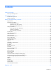
Component identification Front panel components Item Description 1 Hard drive bay 5 (optional)* 2 Hard drive bay 6 (optional)* 3 DVD tray/hard drive bays 7 and 8 (optional)* 4 HP Systems Insight Display 5 Front USB connector 6 Video connector 7 Hard drive bay 4 8 Hard drive bay 3 9 Hard drive bay 2 10 Hard drive bay 1 *An optional hard drive backplane is required when the server is configured with eight hard drives.
Front panel LEDs and buttons Item Description Status 1 UID LED/button Blue = Identification is activated. Flashing blue = System is being managed remotely. Off = Identification is deactivated. 2 Health LED Green = System health is normal. Amber = System health is degraded. To identify the component in a degraded state, see "HP Systems Insight Display and LEDs ("HP Systems Insight Display LEDs" on page 70)". Red = System health is critical.
Rear panel components Item Description 1 Slot 1 PCIe2 x8 (8, 4, 2, 1) 2 Slot 2 PCIe2 x16 (16, 8, 4, 2, 1), 75W +EXT 75W* 3 Power supply bay 1 (populated) 4 Power supply bay 2 5 iLO 2/NIC connector 6 Serial connector 7 Video connector 8 Mouse connector 9 Keyboard connector 10 NIC 2 connector 11 NIC 1 connector 12 USB connectors (2) *This expansion slot provides 75 W of power to an adapter, with an additional 75 W of power supplied by external power.
Rear panel LEDs and buttons Item Description Status 1 10/100/1000 NIC 1 link LED Green = Link exists. Off = No link exists. 2 10/100/1000 NIC 1 activity LED Green = Activity exists. Flashing green = Activity exists. Off = No activity exists. 3 10/100/1000 NIC 2 link LED Green = Link exists. Off = No link exists. 4 10/100/1000 NIC 2 activity LED Green = Activity exists. Flashing green = Activity exists. Off = No activity exists. 5 iLO 2 NIC activity LED Green = Activity exists.
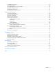
System board components Item Description 1 NMI jumper 2 System maintenance switch 3 10Gb sideband connector (MII) 4 SATA DVD-ROM drive connector 5 SAS cache module connector 6 Power button connector 7 Hard drive data connector 1 (drives 1-4) 8 Hard drive data connector 2 (drives 5-8) 9 Processor 1 DIMM slots (9) 10 Fan module 4 connector 11 Processor socket 1 (populated) 12 Fan module 3 connector 13 Fan module 2 connector 14 Processor socket 2 15 Fan module 1 connector 16 P
Item Description 24 PCI power connector 25 TPM connector 26 PCIe riser board connectors (2) System maintenance switch Position Default Function S1 Off Off = iLO 2 security is enabled. On = iLO 2 security is disabled. S2 Off Off = System configuration can be changed. On = System configuration is locked. S3 Off Reserved S4 Off Reserved S5 Off Off = Power-on password is enabled. On = Power-on password is disabled.
DIMM slots DIMM slots are numbered sequentially (1 through 9) for each processor. The supported AMP modes use the letter assignments for population guidelines. DIMM identification IMPORTANT: This server does not support mixing RDIMMs and UDIMMs. Attempting to mix these two types causes the server to halt during BIOS initialization. The memory subsystem may be populated with either RDIMMs or UDIMMs, but mixing the two types is not supported.
Item Description Definition 2 Rank 1R = Single-rank 2R = Dual-rank 4R = Quad-rank 3 Data width x4 = 4-bit x8 = 8-bit 4 Memory speed 10600 = 1333-MHz 8500 = 1066-MHz 5 DIMM type R = RDIMM (registered) E = UDIMM (unbuffered with ECC) For the latest supported memory information, see the QuickSpecs on the HP website (http://www.hp.com). HP Systems Insight Display LEDs The HP Systems Insight Display LEDs represent the system board layout.
To eject the HP Systems Insight Display: 1. Press and release the display. 2. Extend the display from the chassis. The display can be rotated up to 90 degrees. Systems Insight Display LED combinations When the health LED on the front panel illuminates either amber or red, the server is experiencing a health event. Combinations of illuminated Systems Insight Display LEDs, the system power LED, and the health LED indicate system status.
Systems Insight Display Health LED LED and color Processor (amber) Red System power LED Status Amber One or more of the following conditions may exist: • • • • Processor in socket X has failed. Processor X is not installed in the socket. Processor X is unsupported. ROM detects a failed processor during POST Processor (amber) Amber Green Processor in socket X is in a pre-failure condition. DIMM (amber) Red Green One or more DIMMs have failed.
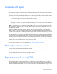
SAS and SATA device numbers • Four hard drive configuration • Eight hard drive configuration SAS and SATA hard drive LEDs Item Description 1 Fault/UID LED (amber/blue) Component identification 73
Item Description 2 Online LED (green) SAS and SATA hard drive LED combinations Online/activity LED (green) Fault/UID LED (amber/blue) Interpretation On, off, or flashing Alternating amber and blue The drive has failed, or a predictive failure alert has been received for this drive; it also has been selected by a management application. On, off, or flashing Steadily blue The drive is operating normally, and it has been selected by a management application.
Fan modules Install fan 2 only when processor 2 is installed. When only one processor is installed, always install the fan blank.
T-10/T-15 Torx screwdriver The server includes a T-10/T-15 Torx screwdriver that ships on the air baffle. Use the screwdriver to loosen screws or thumbscrews, as needed, during procedures.
Cabling Cabling overview This section provides guidelines that help you make informed decisions about cabling the server and hardware options to optimize performance. For information on cabling peripheral components, refer to the white paper on high-density deployment at the HP website (http://www.hp.com/products/servers/platforms). CAUTION: When routing cables, always be sure that the cables are not in a position where they can be pinched or crimped.
• Optional hard drive backplane BBWC battery pack cabling Cabling 78
DVD-ROM and DVD-RW drive cabling Power button and Systems Insight Display cabling Cabling 79
PCI power cabling Cabling 80
Specifications Environmental specifications Specification Value Temperature range* Operating 10°C to 35°C (50°F to 95°F) Shipping -40°C to 70°C (-40°F to 158°F) Maximum wet bulb temperature 28°C (82.4°F) Relative humidity (noncondensing)** Operating 10% to 90% Nonoperating 5% to 95% * All temperature ratings shown are for sea level. An altitude derating of 1°C per 300 m (1.8°F per 1,000 ft) to 3,048 m (10,000 ft) is applicable. No direct sunlight allowed.
Rated input current 5.5 A at 100 VAC 2.
Maximum peak power 800 W at 100V AC input 900 W at 120V AC input 1200 W at 200V to 240V AC input Hot-plug power supply calculations For hot-plug power supply specifications and calculators to determine electrical and heat loading for the server, see the HP Power Advisor website (http://www.hp.com/go/hppoweradvisor).
Acronyms and abbreviations ABEND abnormal end AMP Advanced Memory Protection ASR Automatic Server Recovery BBWC battery-backed write cache CSR Customer Self Repair iLO 2 Integrated Lights-Out 2 IML Integrated Management Log NMI nonmaskable interrupt NVRAM nonvolatile memory PCIe peripheral component interconnect express PCI-X peripheral component interconnect extended RBSU ROM-Based Setup Utility Acronyms and abbreviations 84
SAS serial attached SCSI SATA serial ATA SIM Systems Insight Manager UID unit identification USB universal serial bus Acronyms and abbreviations 85
Documentation feedback HP is committed to providing documentation that meets your needs. To help us improve the documentation, send any errors, suggestions, or comments to Documentation Feedback (mailto:docsfeedback@hp.com). Include the document title and part number, version number, or the URL when submitting your feedback.
Index A access panel 15, 26 additional information 60 air baffle 15, 23, 36 ASR (Automatic Server Recovery) 61 Automatic Server Recovery (ASR) 61 B battery 18, 50, 67 battery-backed write cache battery pack 35 battery-backed write cache cabling 78 battery-backed write cache enabler cabling 78 BBWC battery pack 35 buttons 63, 64, 66 C cables 18, 77 cabling 77 cabling, battery pack 78 cabling, BBWC 78 cache module 39 cache module connector 67 cautions 25 components 15, 63, 65 components, identification 15,
health driver 61 health LEDs 64, 73, 74 heatsink 18, 43 hot-plug power supply 18 HP Insight Diagnostics 23, 60 HP Insight Diagnostics survey functionality 60 HP Insight Remote Support software 61 HP Systems Insight Display 18, 41 I illustrated parts catalog 15 iLO 2 activity LED 66 iLO 2 link LED 66 IML (Integrated Management Log) 61 Insight Diagnostics 60 Integrated Management Log (IML) 61 internal health LED 73, 74 internal USB connector 67 K keyboard connector 65 L LED, health 73 LED, power on 64 LED,
SAS/SATA LED combinations 74 SATA drives 73 SATA DVD drive connector 67 SATA hard drive LEDs 73, 74 SD card slot 67 serial connector 65 server specifications 81 server warnings and cautions 25 specifications 81 specifications, environmental 81 specifications, power 81 specifications, server 81 static electricity 24 symbols on equipment 25 system battery 50, 67 system board battery 67 system board components 67 system board replacement 18, 51 system components 18, 63 system maintenance switch 67, 68 system p