HP ProLiant DL360 G6 Server User Guide Abstract This document describes installation, administration, and troubleshooting for this server. This document is for the person who installs, administers, and troubleshoots servers and storage systems. HP assumes you are qualified in the servicing of computer equipment and trained in recognizing hazards in products with hazardous energy levels.
© Copyright 2009, 2011 Hewlett-Packard Development Company, L.P. The information contained herein is subject to change without notice. The only warranties for HP products and services are set forth in the express warranty statements accompanying such products and services. Nothing herein should be construed as constituting an additional warranty. HP shall not be liable for technical or editorial errors or omissions contained herein. Microsoft®, Windows®, Windows NT® , and Windows Server® are U.S.
Contents Component identification ............................................................................................................... 7 Front panel components ................................................................................................................................ 7 Front panel LEDs and buttons ......................................................................................................................... 8 Rear panel components ...................................
Introduction ............................................................................................................................................... 33 Processor and fan module option ................................................................................................................. 33 Memory options ......................................................................................................................................... 38 Memory subsystem architecture .................
Diagnostic tools ......................................................................................................................................... 80 HP Insight Diagnostics ...................................................................................................................... 80 HP Insight Diagnostics survey functionality .......................................................................................... 80 Integrated Management Log .............................................
Acoustics statement for Germany (Geräuschemission) .................................................................................. 108 Electrostatic discharge ............................................................................................................... 109 Preventing electrostatic discharge .............................................................................................................. 109 Grounding methods to prevent electrostatic discharge ..............................
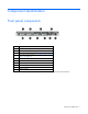
Component identification Front panel components Item Description 1 Hard drive bay 5 (optional)* 2 Hard drive bay 6 (optional)* 3 DVD tray/hard drive bays 7 and 8 (optional)* 4 HP Systems Insight Display ("Access the HP Systems Insight Display" on page 20) 5 Front USB connector 6 Video connector 7 Hard drive bay 4 8 Hard drive bay 3 9 Hard drive bay 2 10 Hard drive bay 1 *An optional hard drive backplane is required when the server is configured with eight hard drives.
Front panel LEDs and buttons Item Description Status 1 UID LED/button Blue = Identification is activated. Flashing blue = System is being managed remotely. Off = Identification is deactivated. 2 Health LED Green = System health is normal. Amber = System health is degraded. To identify the component in a degraded state, see "HP Systems Insight Display and LEDs ("HP Systems Insight Display LEDs" on page 13)". Red = System health is critical.
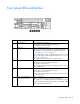
Rear panel components Item Description 1 Slot 1 PCIe2 x8 (8, 4, 2, 1) 2 Slot 2 PCIe2 x16 (16, 8, 4, 2, 1), 75W +EXT 75W* 3 Power supply bay 1 (populated) 4 Power supply bay 2 5 iLO 2/NIC connector 6 Serial connector 7 Video connector 8 Mouse connector 9 Keyboard connector 10 NIC 2 connector 11 NIC 1 connector 12 USB connectors (2) *This expansion slot provides 75 W of power to an adapter, with an additional 75 W of power supplied by external power.
Rear panel LEDs and buttons Item Description Status 1 10/100/1000 NIC 1 link LED Green = Link exists. Off = No link exists. 2 10/100/1000 NIC 1 activity LED Green = Activity exists. Flashing green = Activity exists. Off = No activity exists. 3 10/100/1000 NIC 2 link LED Green = Link exists. Off = No link exists. 4 10/100/1000 NIC 2 activity LED Green = Activity exists. Flashing green = Activity exists. Off = No activity exists. 5 iLO 2 NIC activity LED Green = Activity exists.
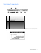
System board components Item Description 1 NMI jumper 2 System maintenance switch 3 10Gb sideband connector (MII) 4 SATA DVD-ROM drive connector 5 SAS cache module connector 6 Power button connector 7 Hard drive data connector 1 (drives 1-4) 8 Hard drive data connector 2 (drives 5-8) 9 Processor 1 DIMM slots (9) 10 Fan module 4 connector 11 Processor socket 1 (populated) 12 Fan module 3 connector 13 Fan module 2 connector 14 Processor socket 2 15 Fan module 1 connector 16 P
Item Description 24 PCI power connector 25 TPM connector 26 PCIe riser board connectors (2) DIMM slots DIMM slots are numbered sequentially (1 through 9) for each processor. The supported AMP modes use the letter assignments for population guidelines. System maintenance switch Position Default Function S1 Off Off = iLO 2 security is enabled. On = iLO 2 security is disabled. S2 Off Off = System configuration can be changed. On = System configuration is locked.
When the system maintenance switch position 6 is set to the On position, the system is prepared to erase all system configuration settings from both CMOS and NVRAM. CAUTION: Clearing CMOS and/or NVRAM deletes configuration information. Be sure to properly configure the server or data loss could occur. NMI jumper The NMI jumper allows administrators to perform a memory dump before performing a hard reset.
Item Description Status All other LEDs Amber = Failure Off = Normal For possible failure causes, see "Systems Insight Display LED combinations (on page 14)." Systems Insight Display LED combinations When the health LED on the front panel illuminates either amber or red, the server is experiencing a health event. Combinations of illuminated Systems Insight Display LEDs, the system power LED, and the health LED indicate system status.
Systems Insight Display Health LED LED and color System power LED Status Power cap (flashing amber) — Amber Power cap has been exceeded. Power cap (green) — Green Power is available. IMPORTANT: If more than one DIMM slot LED is illuminated, further troubleshooting is required. Test each bank of DIMMs by removing all other DIMMs. Isolate the failed DIMM by replacing each DIMM in a bank with a known working DIMM.
SAS and SATA hard drive LEDs Item Description 1 Fault/UID LED (amber/blue) 2 Online LED (green) SAS and SATA hard drive LED combinations Online/activity LED (green) Fault/UID LED (amber/blue) Interpretation On, off, or flashing Alternating amber and blue The drive has failed, or a predictive failure alert has been received for this drive; it also has been selected by a management application.
Online/activity LED (green) Fault/UID LED (amber/blue) Interpretation Off Steadily amber A critical fault condition has been identified for this drive, and the controller has placed it offline. Replace the drive as soon as possible. Off Amber, flashing regularly (1 Hz) A predictive failure alert has been received for this drive. Replace the drive as soon as possible. Off Off The drive is offline, a spare, or not configured as part of an array.
T-10/T-15 Torx screwdriver The server includes a T-10/T-15 Torx screwdriver that ships on the air baffle. Use the screwdriver to loosen screws or thumbscrews, as needed, during procedures.
Operations Power up the server To power up the server, press the Power On/Standby button. Power down the server WARNING: To reduce the risk of personal injury, electric shock, or damage to the equipment, remove the power cord to remove power from the server. The front panel Power On/Standby button does not completely shut off system power. Portions of the power supply and some internal circuitry remain active until AC power is removed.
5. After performing the installation or maintenance procedure, slide the server into the rack: a. Slide the server fully into the rack. b. Secure the server by tightening the thumbscrews. 6. Connect the peripheral cables and power cords. Access the HP Systems Insight Display To eject the HP Systems Insight Display: 1. Press and release the display. 2. Extend the display from the chassis. The display can be rotated up to 90 degrees.
Remove the access panel WARNING: To reduce the risk of personal injury from hot surfaces, allow the drives and the internal system components to cool before touching them. CAUTION: Do not operate the server for long periods with the access panel open or removed. Operating the server in this manner results in improper airflow and improper cooling that can lead to thermal damage. To remove the component: 1. Power down the server (on page 19). 2. Extend the server from the rack (on page 19). 3.
Remove the air baffle 1. Power down the server (on page 19). 2. Extend the server from the rack (on page 19). 3. Remove the access panel (on page 21). 4. Remove the BBWC battery pack, if installed ("Remove the BBWC battery pack" on page 21). 5. Remove the air baffle. Install the air baffle CAUTION: For proper cooling do not operate the server without the access panel, baffles, expansion slot covers, or blanks installed.
1. Install the air baffle. 2. Install the BBWC battery pack, if removed ("Installing the BBWC battery pack" on page 57). 3. Install the access panel (on page 21). 4. Slide the server into the rack. 5. Power up the server (on page 19). Remove the PCI riser board assembly CAUTION: To prevent damage to the server or expansion boards, power down the server and remove all AC power cords before removing or installing the PCI riser board assembly. 1. Power down the server (on page 19). 2.
c. Lift the assembly to unseat the PCI riser boards, and then remove the assembly. Install the PCI riser board assembly CAUTION: To prevent damage to the server or expansion boards, power down the server and remove all AC power cords before removing or installing the PCI riser board assembly. 1. Align the PCI riser boards with the corresponding connectors on the system board, and then install the assembly. 2. Tighten the four PCI riser board assembly thumbscrews. 3.
7. Power up the server (on page 19).
Setup Optional installation services Delivered by experienced, certified engineers, HP Care Pack services help you keep your servers up and running with support packages tailored specifically for HP ProLiant systems. HP Care Packs let you integrate both hardware and software support into a single package. A number of service level options are available to meet your needs.
Space and airflow requirements To allow for servicing and adequate airflow, observe the following space and airflow requirements when deciding where to install a rack: • Leave a minimum clearance of 63.5 cm (25 in) in front of the rack. • Leave a minimum clearance of 76.2 cm (30 in) behind the rack. • Leave a minimum clearance of 121.9 cm (48 in) from the back of the rack to the back of another rack or row of racks.
Power requirements Installation of this equipment must comply with local and regional electrical regulations governing the installation of information technology equipment by licensed electricians. This equipment is designed to operate in installations covered by NFPA 70, 1999 Edition (National Electric Code) and NFPA-75, 1992 (code for Protection of Electronic Computer/Data Processing Equipment).
WARNING: To reduce the risk of personal injury or damage to the equipment, be sure that: • • • • • The leveling jacks are extended to the floor. The full weight of the rack rests on the leveling jacks. The stabilizing feet are attached to the rack if it is a single-rack installation. The racks are coupled together in multiple-rack installations. Only one component is extended at a time. A rack may become unstable if more than one component is extended for any reason.
WARNING: This server is very heavy. To reduce the risk of personal injury or damage to the equipment: • Observe local occupational health and safety requirements and guidelines for manual material handling. • Get help to lift and stabilize the product during installation or removal, especially when the product is not fastened to the rails. When the server weighs more than 22.5 kg (50 lb), at least two people must lift the server into the rack together.
4. Use the strain relief clip from the server hardware kit to secure the power cord. 5. Connect the power cord to the AC source. Powering up and configuring the server To power up the server, press the Power On/Standby button. While the server boots, RBSU and the ORCA utility are automatically configured to prepare the server for operating system installation.
For information on using these installation paths, refer to the SmartStart installation poster in the HP ProLiant Essentials Foundation Pack, included with the server. Registering the server To register the server, refer to the HP Registration website (http://register.hp.com).
Hardware options installation Introduction If more than one option is being installed, read the installation instructions for all the hardware options and identify similar steps to streamline the installation process. WARNING: To reduce the risk of personal injury from hot surfaces, allow the drives and the internal system components to cool before touching them. CAUTION: To prevent damage to electrical components, properly ground the server before beginning any installation procedure.
7. Remove the fan blank. 8. Install the fan module. CAUTION: Failure to completely open the processor locking lever prevents the processor from seating during installation, leading to hardware damage.
9. Open the processor locking lever and the processor socket retaining bracket. Do not remove the processor socket cover. IMPORTANT: Be sure the processor remains inside the processor installation tool. 10. If the processor has separated from the installation tool, carefully re-insert the processor in the tool. Handle the processor by the edges only, and do not touch the bottom of the processor, especially the contact area.
11. Align the processor installation tool with the socket, and then install the processor. THE PINS ON THE SYSTEM BOARD ARE VERY FRAGILE AND EASILY DAMAGED. CAUTION: THE PINS ON THE SYSTEM BOARD ARE VERY FRAGILE AND EASILY DAMAGED. To avoid damage to the system board: • Never install or remove a processor without using the processor installation tool. • Do not touch the processor socket contacts. • Do not tilt or slide the processor when lowering the processor into the socket.
12. Press the tabs on the processor installation tool to separate it from the processor, and then remove the tool. 13. Close the processor socket retaining bracket and the processor locking lever. The processor socket cover is automatically ejected. Remove the cover. CAUTION: Be sure to close the processor socket retaining bracket before closing the processor locking lever. The lever should close without resistance.
14. Remove the thermal interface media protective cover. 15. Install the heatsink. 16. Install the air baffle (on page 22). 17. Install the BBWC battery pack, if removed ("Installing the BBWC battery pack" on page 57). 18. Install the access panel (on page 21). 19. Slide the server into the rack. 20. Power up the server (on page 19). Memory options IMPORTANT: This server does not support mixing RDIMMs and UDIMMs.
The memory subsystem in this server can support RDIMMs or UDIMMs. Both types are referred to as DIMMs when the information applies to both types. When specified as RDIMM or UDIMM, the information applies to that type only. All memory installed in the server must be the same type.
DIMM identification To determine DIMM characteristics, use the label attached to the DIMM and the following illustration and table. Item Description Definition 1 Size — 2 Rank 1R = Single-rank 2R = Dual-rank 4R = Quad-rank 3 Data width x4 = 4-bit x8 = 8-bit 4 Voltage rating L = Low voltage (1.
Advanced Memory Protection options are configured in RBSU. If the requested AMP mode is not supported by the installed DIMM configuration, the server boots in Advanced ECC mode. For more information, see "HP ROM-Based Setup Utility (on page 73)." For the latest memory configuration information, see the QuickSpecs on the HP website (http://www.hp.com). RDIMM maximum memory configurations The following table lists the maximum memory configuration possible with 8-GB RDIMMs.
General DIMM slot population guidelines Observe the following guidelines for all AMP modes: • Populate DIMM slots for a processor only if the processor is installed. • To maximize performance in multi-processor configurations, distribute the total memory capacity between all processors as evenly as possible. • Do not mix Unbuffered and Registered PC3 DIMMs. • Each channel supports up to two Unbuffered DIMMs.
• Always install DIMMs in channels 1 and 2 for each installed processor. • Do not install DIMMs in channel 3 for any processor. • DIMMs installed on channel 1 and channel 2 of an installed processor must be identical. • In multi-processor configurations, each processor must have a valid Mirrored Memory configuration. • In multi-processor configurations, each processor may have a different valid Mirrored Memory configuration.
• Observe the general DIMM slot population guidelines (on page 42). • Always install DIMMs in channels 1 and 2 for each installed processor. • Do not install DIMMs in channel 3 for any processor. • DIMM configuration on channel 1 and channel 2 of a processor must be identical. • In multi-processor configurations, each processor must have a valid Lockstep Memory configuration. • In multi-processor configurations, each processor may have a different valid Lockstep Memory configuration.
CAUTION: To avoid damage to the hard drives, memory, and other system components, the air baffle, drive blanks, and access panel must be installed when the server is powered up. 1. Power down the server (on page 19). 2. Extend the server from the rack (on page 19). 3. Remove the access panel (on page 21). 4. Remove the BBWC battery pack, if installed ("Remove the BBWC battery pack" on page 21). 5. Remove the air baffle (on page 22). 6. Open the DIMM slot latches. 7. Install the DIMM. 8.
Removing hard drive blanks CAUTION: To prevent improper cooling and thermal damage, do not operate the server unless all bays are populated with either a component or a blank. Remove the component as indicated. Removing hard drive bezel blanks CAUTION: To prevent improper cooling and thermal damage, do not operate the server unless all bays are populated with either a component or a blank. To remove the component: 1. Remove hard drives 1 and 2 ("Removing a hot-plug SAS hard drive" on page 47). 2.
Remove the component as indicated. Removing a hot-plug SAS hard drive CAUTION: For proper cooling do not operate the server without the access panel, baffles, expansion slot covers, or blanks installed. If the server supports hot-plug components, minimize the amount of time the access panel is open. 1. Determine the status of the hard drive from the hot-plug SAS hard drive LED combinations ("SAS and SATA hard drive LED combinations" on page 16). 2. Back up all server data on the hard drive. 3.
2. Prepare the hard drive. 3. Install the hard drive. 4. Determine the status of the hard drive from the hot-plug SAS hard drive LED combinations ("SAS and SATA hard drive LED combinations" on page 16). DVD-ROM and DVD-RW drive option This server supports the installation of a DVD-ROM drive or a DVD-RW drive. When an optical drive is installed, the server does not support the additional hard drive backplane. To install the component: 1. Power down the server (on page 19). 2.
5. Install the DVD-ROM drive in the DVD tray. 6. Secure the drive to the tray using the screw from this kit and the T-10/T-15 Torx screwdriver provided with the server. 7. Install the DVD tray using the screws from this kit and the T-10/T-15 Torx screwdriver provided with the server. 8. Remove the BBWC battery pack, if installed ("Remove the BBWC battery pack" on page 21). 9. Remove the air baffle (on page 22).
10. Remove fan modules 3 and 4. 11. Connect the cable to the rear of the drive and to the SATA DVD-ROM drive connector on the system board. 12. Route the cable along the edge of the system board.
13. Install fan modules 3 and 4. 14. Install the air baffle (on page 22). 15. Install the BBWC battery pack, if removed ("Installing the BBWC battery pack" on page 57). 16. Install the access panel (on page 21). 17. Slide the server into the rack. 18. Power up the server (on page 19). Hard drive blackplane option When the hard drive backplane option is installed, the server does not support the DVD-ROM or DVD-RW drive options. To install the component: 1. Power down the server (on page 19). 2.
7. Install the hard drive cage. 8. Remove the BBWC battery pack, if installed ("Remove the BBWC battery pack" on page 21). 9. Remove the air baffle (on page 22). 10. Remove the fan blank.
11. Remove all fan modules. 12. Connect the hard drive power cable and the hard drive data cable to the connectors on the hard drive backplane assembly.
13. Align and install the optional hard drive backplane assembly. 14. Connect the hard drive power cable and the hard drive data cable to the connectors on the system board.
15. Install all fan modules. 16. Install the fan blank. 17. Install the air baffle (on page 22). 18. Install the BBWC battery pack, if removed ("Installing the BBWC battery pack" on page 57). 19. Install hard drives or hard drive blanks into each bay. 20. Install the access panel (on page 21). 21. Slide the server into the rack. 22. Power up the server (on page 19). 23. Determine the status of the hard drive from the SAS and SATA hard drive LED combinations (on page 16).
The Battery-Backed Write Cache Enabler, also called the battery pack, works with the cache module to provide transportable data protection, increase overall controller performance, and maintain any cached data for up to 72 hours. The NiMH batteries in the battery pack are continuously recharged through a trickle-charging process whenever the system power is on. Under normal operating conditions, the battery pack lasts for 3 years before replacement is necessary.
5. Install the cache module in the SAS cache module connector on the system board. For connector locations, see "System board components (on page 11)." 6. Install the PCI riser board assembly (on page 24). 7. Install the access panel (on page 21). 8. Slide the server into the rack. 9. Power up the server (on page 19). Installing the BBWC battery pack 1. Power down the server (on page 19). 2. Extend the server from the rack (on page 19). 3. Remove the access panel (on page 21). 4.
7. Connect the BBWC cable to the cache module. 8. Install the PCI riser board assembly (on page 24). 9. Install the access panel (on page 21). 10. Slide the server into the rack. 11. Power up the server (on page 19). Expansion board options Installing an expansion board The server ships with PCIe riser boards and expansion slots. PCI-X expansion boards are supported with optional riser boards.
6. Install the expansion board into the slot until it seats firmly. 7. Install the PCI riser board assembly (on page 24). IMPORTANT: The server does not power up if the PCI riser board assembly is not seated properly. NOTE: The same procedures apply for installing an expansion board in PCI expansion slot 1. 8. Connect all internal or external cabling to the expansion boards. 9. Install the access panel (on page 21). 10. Slide the server into the rack. 11. Power up the server (on page 19).
6. Remove the full-length PCIe riser board from the riser board assembly. 7. Install the PCI-X riser board on the riser board assembly. IMPORTANT: If the expansion board ships with an extender bracket, remove it from the expansion board before inserting the board into the expansion slot of the PCI riser board assembly. 8. Install the expansion boards, if necessary. 9. Install the PCI riser board assembly (on page 24).
Before installing a high-power graphics adapter (150W) in the server, be sure that the power supplies support the installation of the adapter. Due the high power requirements for the adapter, a 750W power supply may be required. For more information, see the HP Enterprise Configurator website (http://h30099.www3.hp.com/configurator/). To install the component: 1. Power down the server (on page 19). 2. Extend the server from the rack (on page 19). 3. Remove the access panel (on page 21). 4.
10. Install the graphics adapter in slot 2 on the PCI riser board assembly. 11. Install the PCI riser board assembly (on page 24). 12. Connect the PCI power cable to the connector on the 150W graphics adapter and the system board. 13. Install the air baffle (on page 22). 14. Install the BBWC battery pack, if removed ("Installing the BBWC battery pack" on page 57). 15. Install the access panel (on page 21). 16. Slide the server into the rack. 17. Power up the server (on page 19).
HP NC522SFP Dual Port 10GbE Server Adapter option To install the component: 1. Power down the server (on page 19). 2. Extend the server from the rack (on page 19). 3. Remove the access panel (on page 21). 4. Remove the PCI riser board assembly (on page 23). 5. Remove expansion slot cover 1 from the PCI riser board assembly. 6. Install the adapter in slot 1 on the PCI riser board assembly. 7. Install the PCI riser board assembly (on page 24). 8. Install the access panel (on page 21). 9.
CAUTION: To prevent improper cooling and thermal damage, do not operate the server unless all bays are populated with either a component or a blank. To install the component: 1. Unfasten the cable management solution to access the power supply bays. 2. Remove the power supply blank. 3. Remove the protective cover from the connector pins on the power supply.
4. Install the redundant power supply into the bay until it clicks. 5. Connect the power cord to the power supply. 6. Use the strain relief clip from the server hardware kit to secure the power cord. 7. Route the power cord through the cable management solution. 8. Connect the power cord to the power source. 9. Be sure that the power supply LED is green. HP Trusted Platform Module option Use these instructions to install and enable a TPM on a supported server.
Enabling the TPM requires accessing the ROM-Based Setup Utility (RBSU) ("HP ROM-Based Setup Utility" on page 73). For more information about RBSU, see the HP website (http://www.hp.com/support/smartstart/documentation). TPM installation requires the use of drive encryption technology, such as the Microsoft® Windows® BitLocker™ Drive Encryption feature. For more information on BitLocker™, see the Microsoft website (http://www.microsoft.com). CAUTION: Always observe the guidelines in this document.
5. Install the TPM board. Press down on the connector to seat the board ("System board components" on page 11). 6. Install the TPM security rivet by pressing the rivet firmly into the system board. 7. Install the PCI riser board assembly (on page 24). 8. Install the access panel (on page 21). 9. Slide the server into the rack. 10. Power up the server (on page 19).
• Always store the recovery key/password in multiple locations. • Always store copies of the recovery key/password away from the server. • Do not save the recovery key/password on the encrypted hard drive. Enabling the Trusted Platform Module 1. When prompted during the start-up sequence, access RBSU by pressing the F9 key. 2. From the Main Menu, select Server Security. 3. From the Server Security Menu, select Trusted Platform Module. 4.
Cabling Cabling overview This section provides guidelines that help you make informed decisions about cabling the server and hardware options to optimize performance. For information on cabling peripheral components, refer to the white paper on high-density deployment at the HP website (http://www.hp.com/products/servers/platforms). CAUTION: When routing cables, always be sure that the cables are not in a position where they can be pinched or crimped.
• Optional hard drive backplane BBWC battery pack cabling Cabling 70
DVD-ROM and DVD-RW drive cabling Power button and Systems Insight Display cabling Cabling 71
PCI power cabling Cabling 72
Software and configuration utilities Configuration tools SmartStart software SmartStart is a collection of software that optimizes single-server setup, providing a simple and consistent way to deploy server configuration. SmartStart has been tested on many ProLiant server products, resulting in proven, reliable configurations.
• Displaying system information • Selecting the primary boot controller • Configuring memory options • Language selection For more information on RBSU, see the HP ROM-Based Setup Utility User Guide on the Documentation CD or the HP website (http://www.hp.com/support/smartstart/documentation). Using RBSU To use RBSU, use the following keys: • To access RBSU, press the F9 key during power-up when prompted. • To navigate the menu system, use the arrow keys.
By default, the auto-configuration process configures the system for the English language. To change any default settings in the auto-configuration process (such as the settings for language, operating system, and primary boot controller), execute RBSU by pressing the F9 key when prompted. After the settings are selected, exit RBSU and allow the server to reboot automatically. For more information on RBSU, see the HP ROM-Based Setup Utility User Guide on the Documentation CD or the HP website (http://www.
Configuring mirrored memory To configure mirrored memory: 1. Install the required DIMMs ("Installing a DIMM" on page 44). 2. Access RBSU by pressing the F9 key during power-up when the prompt is displayed. 3. Select System Options. 4. Select Advanced Memory Protection. 5. Select Mirrored Memory with Advanced ECC Support. 6. Press the Enter key. 7. Press the Esc key to exit the current menu or press the F10 key to exit RBSU.
• Mozilla Firefox 2.0 or later For Linux servers, see the README.TXT file for additional browser and support information. For more information, see the Configuring Arrays on HP Smart Array Controllers Reference Guide on the Documentation CD or the HP website (http://www.hp.com). Option ROM Configuration for Arrays Before installing an operating system, you can use the ORCA utility to create the first logical drive, assign RAID levels, and establish online spare configurations.
Management tools Automatic Server Recovery ASR is a feature that causes the system to restart when a catastrophic operating system error occurs, such as a blue screen, ABEND (does not apply to HP ProLiant DL980 Servers), or panic. A system fail-safe timer, the ASR timer, starts when the System Management driver, also known as the Health Driver, is loaded. When the operating system is functioning properly, the system periodically resets the timer.
Erase Utility CAUTION: Perform a backup before running the System Erase Utility. The utility sets the system to its original factory state, deletes the current hardware configuration information, including array setup and disk partitioning, and erases all connected hard drives completely. Refer to the instructions for using this utility. Run the Erase Utility if you must erase the system for the following reasons: • You want to install a new operating system on a server with an existing operating system.
Internal USB functionality An internal USB connector is available for use with USB drive keys only. This solution provides for use of a permanent boot drive from a USB drive key installed in the internal connector, avoiding issues of clearance on the front of the rack and physical access to secure data. For additional security, you can disable the external USB connectors through RBSU. Disabling the rear USB connectors in RBSU disables both rear USB ports.
NOTE: The current version of SmartStart provides the memory spare part numbers for the server. To download the latest version, see the HP website (http://www.hp.com/support). Integrated Management Log The IML records hundreds of events and stores them in an easy-to-view form. The IML timestamps each event with 1-minute granularity.
Keeping the system current Drivers IMPORTANT: Always perform a backup before installing or updating device drivers. The server includes new hardware that may not have driver support on all OS installation media. If you are installing a SmartStart-supported OS, use the SmartStart software (on page 73) and its Assisted Path feature to install the OS and latest driver support.
• Requires no agent for remote installations • Enables dependency checking, which ensures appropriate install order and dependency checking between components • Deploys software and firmware on Windows and Linux operating systems • Performs local or remote (one-to-many) online deployment • Deploys firmware and software together • Supports offline and online deployment • Deploys necessary component updates only • Downloads the latest components from Web • Enables direct update of BMC firmwar
Troubleshooting Troubleshooting resources The HP ProLiant Servers Troubleshooting Guide provides procedures for resolving common problems and comprehensive courses of action for fault isolation and identification, error message interpretation, issue resolution, and software maintenance on ProLiant servers and server blades. This guide includes problem-specific flowcharts to help you navigate complex troubleshooting processes. To view the guide, select a language: • English (http://www.hp.
Symbols on equipment The following symbols may be placed on equipment to indicate the presence of potentially hazardous conditions. This symbol indicates the presence of hazardous energy circuits or electric shock hazards. Refer all servicing to qualified personnel. WARNING: To reduce the risk of injury from electric shock hazards, do not open this enclosure. Refer all maintenance, upgrades, and servicing to qualified personnel. This symbol indicates the presence of electric shock hazards.
WARNING: To reduce the risk of electric shock or damage to the equipment: • Do not disable the power cord grounding plug. The grounding plug is an important safety feature. • Plug the power cord into a grounded (earthed) electrical outlet that is easily accessible at all times. • Unplug the power cord from the power supply to disconnect power to the equipment. • Do not route the power cord where it can be walked on or pinched by items placed against it.
2. Record any error messages displayed by the system. 3. Remove all diskettes, CD-ROMs, DVD-ROMs, and USB drive keys. 4. Power down the server and peripheral devices if you will be diagnosing the server offline. If possible, always perform an orderly shutdown: a. Exit any applications. b. Exit the operating system. c. Power down the server (on page 19). 5. Disconnect any peripheral devices not required for testing (any devices not necessary to power up the server).
When requested to break the server down to the minimum configuration, uninstall the following components, if installed: • All additional DIMMs Leave only the minimum required to boot the server—either one DIMM or a pair of DIMMs. For more information, see the memory guidelines in the server user guide. • All additional cooling fans, if applicable For the minimum fan configuration, see the server user guide.
Service notifications To view the latest service notifications, refer to the HP website (http://www.hp.com/go/bizsupport). Select the appropriate server model, and then click the Troubleshoot a Problem link on the product page. Server health LEDs Some servers have an internal health LED and an external health LED, while other servers have a single system health LED. The system health LED provides the same functionality as the two separate internal and external health LEDs.
General diagnosis flowchart The General diagnosis flowchart provides a generic approach to troubleshooting. If you are unsure of the problem, or if the other flowcharts do not fix the problem, use the following flowchart. Item See 1 "Symptom information (on page 86)" 2 "Loose connections (on page 88)" 3 "Service notifications (on page 89)" 4 The most recent version of a particular server or option firmware is available on the HP Support website (http://www.hp.com/support).
Item See 5 "General memory problems are occurring" in the HP ProLiant Servers Troubleshooting Guide located on the Documentation CD or see "Troubleshooting resources (on page 84)" 6 Server maintenance and service guide, located on the Documentation CD or the HP website (http://www.hp.
Server power-on problems flowchart Symptoms: • The server does not power on. • The system power LED is off or amber.
• The external health LED is red or amber. • The internal health LED is red or amber. NOTE: For the location of server LEDs and information on their statuses, refer to the server documentation.
Troubleshooting 94
POST problems flowchart Symptoms: • Server does not complete POST NOTE: The server has completed POST when the system attempts to access the boot device.
Item See 13 • • "Server information you need" in the HP ProLiant Servers Troubleshooting Guide located on the Documentation CD or see "Troubleshooting resources (on page 84)" "Operating system information you need" in the HP ProLiant Servers Troubleshooting Guide located on the Documentation CD or see "Troubleshooting resources (on page 84)" Troubleshooting 96
OS boot problems flowchart Symptoms: • Server does not boot a previously installed operating system • Server does not boot SmartStart Possible causes: • Corrupted operating system • Hard drive subsystem problem • Incorrect boot order setting in RBSU Item See 1 HP ROM-Based Setup Utility User Guide (http://www.hp.
Server fault indications flowchart Symptoms: • Server boots, but a fault event is reported by Insight Management Agents • Server boots, but the internal health LED, external health LED, or component health LED is red or amber NOTE: For the location of server LEDs and information on their statuses, refer to the server documentation.
Possible causes: • Improperly seated or faulty internal or external component • Unsupported component installed • Redundancy failure • System overtemperature condition Item See 1 • • "Integrated Management Log" or in the HP ProLiant Servers Troubleshooting Guide located on the Documentation CD or see "Troubleshooting resources (on page 84)" "Event list error messages" in the HP ProLiant Servers Troubleshooting Guide located on the Documentation CD or see "Troubleshooting resources (on page 84)"
POST error messages and beep codes For a complete listing of error messages, refer to the "POST error messages" in the HP ProLiant Servers Troubleshooting Guide located on the Documentation CD or on the HP website (http://www.hp.com/support).
WARNING: To avoid potential problems, ALWAYS read the warnings and cautionary information in the server documentation before removing, replacing, reseating, or modifying system components.
System battery If the server no longer automatically displays the correct date and time, you may need to replace the battery that provides power to the real-time clock. Under normal use, battery life is 5 to 10 years. WARNING: The computer contains an internal lithium manganese dioxide, a vanadium pentoxide, or an alkaline battery pack. A risk of fire and burns exists if the battery pack is not properly handled. To reduce the risk of personal injury: • • • • Do not attempt to recharge the battery.
Regulatory compliance notices Regulatory compliance identification numbers For the purpose of regulatory compliance certifications and identification, this product has been assigned a unique regulatory model number. The regulatory model number can be found on the product nameplate label, along with all required approval markings and information. When requesting compliance information for this product, always refer to this regulatory model number.
radio communications. However, there is no guarantee that interference will not occur in a particular installation. If this equipment does cause harmful interference to radio or television reception, which can be determined by turning the equipment off and on, the user is encouraged to try to correct the interference by one or more of the following measures: • Reorient or relocate the receiving antenna. • Increase the separation between the equipment and receiver.
This Class A digital apparatus meets all requirements of the Canadian Interference-Causing Equipment Regulations. Cet appareil numérique de la classe A respecte toutes les exigences du Règlement sur le matériel brouilleur du Canada. Class B equipment This Class B digital apparatus meets all requirements of the Canadian Interference-Causing Equipment Regulations. Cet appareil numérique de la classe B respecte toutes les exigences du Règlement sur le matériel brouilleur du Canada.
This symbol on the product or on its packaging indicates that this product must not be disposed of with your other household waste. Instead, it is your responsibility to dispose of your waste equipment by handing it over to a designated collection point for the recycling of waste electrical and electronic equipment.
Class B equipment Chinese notice Class A equipment Laser compliance This product may be provided with an optical storage device (that is, CD or DVD drive) and/or fiber optic transceiver. Each of these devices contains a laser that is classified as a Class 1 Laser Product in accordance with US FDA regulations and the IEC 60825-1. The product does not emit hazardous laser radiation. Each laser product complies with 21 CFR 1040.10 and 1040.11 except for deviations pursuant to Laser Notice No.
For more information about battery replacement or proper disposal, contact an authorized reseller or an authorized service provider. Taiwan battery recycling notice The Taiwan EPA requires dry battery manufacturing or importing firms in accordance with Article 15 of the Waste Disposal Act to indicate the recovery marks on the batteries used in sales, giveaway or promotion. Contact a qualified Taiwanese recycler for proper battery disposal.
Electrostatic discharge Preventing electrostatic discharge To prevent damaging the system, be aware of the precautions you need to follow when setting up the system or handling parts. A discharge of static electricity from a finger or other conductor may damage system boards or other static-sensitive devices. This type of damage may reduce the life expectancy of the device. To prevent electrostatic damage: • Avoid hand contact by transporting and storing products in static-safe containers.
Specifications Environmental specifications Specification Value Temperature range* Operating 10°C to 35°C (50°F to 95°F) Shipping -40°C to 70°C (-40°F to 158°F) Maximum wet bulb temperature 28°C (82.4°F) Relative humidity (noncondensing)** Operating 10% to 90% Non-operating 5% to 95% * All temperature ratings shown are for sea level. An altitude derating of 1°C per 300 m (1.8°F per 1,000 ft) to 3048 m (10,000 ft) is applicable. No direct sunlight allowed.
Rated input current 5.5 A at 100 VAC 2.
Maximum peak power 800 W at 100V AC input 900 W at 120V AC input 1200 W at 200V to 240V AC input CAUTION: This equipment is designed to permit the connection of the earthed conductor of the DC supply circuit to the earthing conductor at the equipment. See installation instructions. CAUTION: This equipment is designed to permit the connection of the earthed conductor of the DC supply circuit to the earthing conductor at the equipment.
Technical support Before you contact HP Be sure to have the following information available before you call HP: • Technical support registration number (if applicable) • Product serial number • Product model name and number • Product identification number • Applicable error messages • Add-on boards or hardware • Third-party hardware or software • Operating system type and revision level HP contact information For United States and worldwide contact information, see the Contact HP website (h
NOTE: Some HP parts are not designed for customer self repair. In order to satisfy the customer warranty, HP requires that an authorized service provider replace the part. These parts are identified as "No" in the Illustrated Parts Catalog. Based on availability and where geography permits, CSR parts will be shipped for next business day delivery. Same day or four-hour delivery may be offered at an additional charge where geography permits.
Riparazione da parte del cliente Per abbreviare i tempi di riparazione e garantire una maggiore flessibilità nella sostituzione di parti difettose, i prodotti HP sono realizzati con numerosi componenti che possono essere riparati direttamente dal cliente (CSR, Customer Self Repair). Se in fase di diagnostica HP (o un centro di servizi o di assistenza HP) identifica il guasto come riparabile mediante un ricambio CSR, HP lo spedirà direttamente al cliente per la sostituzione.
CSR-Teile werden abhängig von der Verfügbarkeit und vom Lieferziel am folgenden Geschäftstag geliefert. Für bestimmte Standorte ist eine Lieferung am selben Tag oder innerhalb von vier Stunden gegen einen Aufpreis verfügbar. Wenn Sie Hilfe benötigen, können Sie das HP technische Support Center anrufen und sich von einem Mitarbeiter per Telefon helfen lassen. Den Materialien, die mit einem CSR-Ersatzteil geliefert werden, können Sie entnehmen, ob das defekte Teil an HP zurückgeschickt werden muss.
Para obtener más información acerca del programa de Reparaciones del propio cliente de HP, póngase en contacto con su proveedor de servicios local. Si está interesado en el programa para Norteamérica, visite la página web de HP siguiente (http://www.hp.com/go/selfrepair). Customer Self Repair Veel onderdelen in HP producten zijn door de klant zelf te repareren, waardoor de reparatieduur tot een minimum beperkt kan blijven en de flexibiliteit in het vervangen van defecte onderdelen groter is.
Opcional – Peças cujo reparo feito pelo cliente é opcional. Essas peças também são projetadas para o reparo feito pelo cliente. No entanto, se desejar que a HP as substitua, pode haver ou não a cobrança de taxa adicional, dependendo do tipo de serviço de garantia destinado ao produto. OBSERVAÇÃO: Algumas peças da HP não são projetadas para o reparo feito pelo cliente. A fim de cumprir a garantia do cliente, a HP exige que um técnico autorizado substitua a peça.
Technical support 119
Technical support 120
Acronyms and abbreviations ABEND abnormal end AMP Advanced Memory Protection ASR Automatic Server Recovery BBWC battery-backed write cache CMOS complementary metal-oxide semiconductor CSA Canadian Standards Association CSR Customer Self Repair DDR double data rate DRAM dynamic random access memory IEC International Electrotechnical Commission iLO 2 Integrated Lights-Out 2 IML Integrated Management Log Acronyms and abbreviations 121
NFPA National Fire Protection Association NIC network interface controller NMI non-maskable interrupt NVRAM non-volatile memory ORCA Option ROM Configuration for Arrays PCI peripheral component interface PCI Express Peripheral Component Interconnect Express PCIe peripheral component interconnect express PCI-X peripheral component interconnect extended POST Power-On Self Test PSP ProLiant Support Pack PXE Preboot Execution Environment RBSU ROM-Based Setup Utility RDIMM Registered Dual In-line Me
RDP Rapid Deployment Pack SAS serial attached SCSI SATA serial ATA SFF small form-factor SIM Systems Insight Manager TMRA recommended ambient operating temperature TPM trusted platform module UDIMM Unregistered Dual In-Line Memory Module UID unit identification UPS uninterruptible power system USB universal serial bus VCA Version Control Agent Acronyms and abbreviations 123
Index 1 10Gb sideband connector 11 A access panel 21 ACU (Array Configuration Utility) 76 additional information 84 Advanced ECC memory 41, 42, 75 air baffle 22 airflow requirements 27 AMP (Advanced Memory Protection) 75 AMP modes 75 Array Configuration Utility (ACU) 76 ASR (Automatic Server Recovery) 78 authorized reseller 113 authorized technician 85 auto-configuration process 74 Automatic Server Recovery (ASR) 78 B Basic Input/Output System (BIOS) 75, 78, 90 battery 11, 21, 57, 107 battery pack, removi
Erase Utility 79 error messages 100 European Union notice 105 expansion boards 58 extending server from rack 19 external USB functionality 80 F fan connectors 11 fan module connector 11 FCC (Federal Communications Commission) notice 103, 104 features 7 Federal Communications Commission (FCC) notice 103, 104 firmware upgrade utility, troubleshooting 84 flowcharts 89, 90, 92, 95, 97, 98 front panel buttons 8 front panel components 7 front panel LEDs 8 G general diagnosis flowchart 90 graphics card cabling 7
memory, Advanced ECC 75 memory, mirrored 41, 42, 43, 75, 76 memory, online spare 75 memory, RAID 75 minimum hardware configuration 87 mirrored memory 41, 42, 75, 76 mouse connector 9 N NIC connectors 9 NMI switch 11 O online spare memory 75 operating systems 31, 82 optimum environment 26 Option ROM Configuration for Arrays (ORCA) 77 options installation 29, 33 ORCA (Option ROM Configuration for Arrays) 77 OS boot problems flowchart 97 overtemperature LED 13 P passwords 67 PCI expansion slots 19 PCI power
SAS drives 16 SATA DVD drive connector 11 scripted installation 73 SD card slot 11 serial connector 9 serial number 77 series number 103 server adapter option 63 server fault indications flowchart 98 server features and options 33 server options, installing 29, 33 service notifications 89 shipping carton contents 29 site requirements 27 Smart Update Manager 82 SmartStart autorun menu 73 SmartStart Scripting Toolkit 73 SmartStart, overview 73 space requirements 27 specifications, power 110 specifications, se