
User Manual

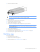
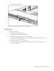


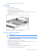

Table Of Contents
- HP ProLiant DL360 G7 Server Maintenance and Service Guide
- Notice
- Contents
- Customer self repair
- Illustrated parts catalog
- Removal and replacement procedures
- Required tools
- Preparation procedures
- Safety considerations
- Access panel
- Hard drive bezel blanks
- Dual bezel blank
- Hard drive blank
- SAS and SATA hard drive
- Power supply blank
- Hot-plug power supply
- Hard drive cage
- DVD tray
- DVD-ROM or DVD-RW drive
- Fan module
- Fan blank
- BBWC battery pack or FBWC capacitor pack
- Air baffle
- PCI riser board assembly
- Expansion boards
- PCIe riser board
- PCI-X riser board
- Cache module
- Optional hard drive backplane assembly (top)
- Standard hard drive backplane assembly (bottom)
- Systems Insight Display, LED, and power button assembly
- DIMMs
- Heatsink
- Processor
- System battery
- System board
- HP Trusted Platform Module
- Cabling
- Diagnostic tools
- Component identification
- Specifications
- Environmental specifications
- Server specifications
- Power supply specifications
- HP 460 W CS HE Power Supply (92%) specifications
- HP 460 W CS Platinum Power Supply (94%) specifications
- HP 750 W CS HE Power Supply (92%) specifications
- HP 750 W CS Platinum Power Supply (94%) specifications
- HP 1200 W CS HE Power Supply (90%) specifications
- HP 1200 W CS -48Vdc Power Supply specifications
- Hot-plug power supply calculations
- Acronyms and abbreviations
- Index
Removal and replacement procedures 38
To replace the component, reverse the removal procedure.
Air baffle
To remove the component:
1. Power down the server (on page 25).
2. Extend the server from the rack (on page 26).
3. Remove the access panel ("Access panel" on page 28).
4. If installed, remove the BBWC battery pack or the FBWC capacitor pack ("BBWC battery pack or
FBWC capacitor pack" on page 37).
5. Remove the air baffle.
To replace the component, reverse the removal procedure.
PCI riser board assembly
To remove the component:
CAUTION: To prevent damage to the server or expansion boards, power down the server
and remove all AC power cords before removing or installing the PCI riser board assembly.
1. Power down the server (on page 25).
2. Extend the server from the rack (on page 26).
3. Remove the access panel ("Access panel" on page 28).
4. If installed, remove the BBWC battery pack or the FBWC capacitor pack ("BBWC battery pack or
FBWC capacitor pack" on page 37).
5. Remove the air baffle ("Air baffle" on page 38).
6. Remove the PCI riser board assembly:
a. Disconnect external cables connected to any existing expansion boards.
b. Loosen the four PCI riser board assembly thumbscrews.