HP ProLiant DL360e Gen8 Server User Guide Abstract This document is for the person who installs, administers, and troubleshoots servers and storage systems. HP assumes you are qualified in the servicing of computer equipment and trained in recognizing hazards in products with hazardous energy levels.
© Copyright 2012 Hewlett-Packard Development Company, L.P. The information contained herein is subject to change without notice. The only warranties for HP products and services are set forth in the express warranty statements accompanying such products and services. Nothing herein should be construed as constituting an additional warranty. HP shall not be liable for technical or editorial errors or omissions contained herein. Microsoft® and Windows® are U.S. registered trademarks of Microsoft Corporation.
Contents Component identification ............................................................................................................... 7 Front panel components ............................................................................................................................. 7 Front panel LEDs and buttons ............................................................................................................ 8 Rear panel components ...................................................
Security bezel option ............................................................................................................................... 29 Front video adapter option ....................................................................................................................... 29 Drive options .......................................................................................................................................... 30 Drive installation guidelines .......................
Auto-configuration process .............................................................................................................. 83 Boot options ................................................................................................................................. 84 Configuring AMP modes ................................................................................................................ 84 Re-entering the server serial number and product ID ...................................
HP 460 W CS power supply (92% efficiency) ................................................................................. 101 HP 460 W CS HE power supply (94% efficiency) ............................................................................ 101 HP 750 W CS power supply (92% efficiency) ................................................................................. 101 HP 750 W CS HE power supply (94% efficiency) ............................................................................
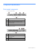
Component identification Front panel components • Four-bay LFF drive model Item Description 1 Optical drive (optional) 2 Serial number pull tab 3 Front video connector (front video adapter, part number 655915-B21 required) 4 USB connectors 5 LFF drives • Eight-bay SFF drive model Item Description 1 Optical drive (optional) 2 Front video connector (front video adapter, part number 655915-B21 required) 3 USB connectors 4 Serial number pull tab 5 SFF drives Component identification
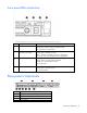
Front panel LEDs and buttons Item Description Status 1 UID LED/button Blue = Identification is activated. Flashing blue = System is being managed remotely. Off = Identification is deactivated. 2 Power On/Standby button and system power LED Green = System is on. Flashing green = Waiting for power. Amber = System is in standby, but power is still applied. Off = Power cord is not attached or power supply failed. 3 Health LED Green = System is on and system health is normal.
Item Description 5 NIC connectors (4 to 1) 6 Serial connector 7 Video connector 8 USB connectors 9 iLO connector Rear panel LEDs and buttons Item Description Status 1 NIC status LED Green = Activity exists Flashing green = Activity exists Off = No activity exists 2 NIC link LED Green = Link exists Off = No link exists 3 UID LED/button Blue = Activated Flashing blue = System being remotely managed Off = Deactivated 4 Power supply LED Green = Normal Off = One or more of the followin
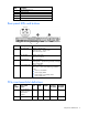
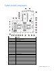
System board components Item Description 1 PCI riser connectors 2 Cache module connector 3 TPM connector 4 Mini-SAS connector 5 System battery 6 SATA drive connector 7 SATA optical/storage drive connector 8 Front panel connectors 9 Processor socket 1 10 GPU power connector 11 Fan connector 8 12 Fan connector 7 13 Fan connector 6 14 Fan connector 5 15 Fan connector 4 16 Internal USB connector 17 Fan connector 3 18 Fan connector 2 19 Fan connector 1 20 Processor 2 DIM
Item Description 21 Not applicable 22 Drive backplane power connector 23 Processor socket 2 24 Not applicable 25 Power supply connector 1 26 Drive sideband signal connector 27 Power supply connector 2 28 Processor 1 DIMM slots 29 SD card slot 30 NMI header 31 System maintenance switch DIMM slot locations DIMM slots are numbered sequentially (1 through 6) for each processor. The supported AMP modes use the letter assignments for population guidelines.
Switch Default Function 3, 4, 7, 8, 9, 10, 11, 12 — Reserved When the system maintenance switch position 6 is set to the On position, the system is prepared to erase all system configuration settings from both CMOS and NVRAM. CAUTION: Clearing CMOS and/or NVRAM deletes configuration information. Be sure to properly configure the server or data loss could occur. NMI header The NMI header enables administrators to perform a memory dump before performing a hard reset.
Drive LED definitions Item LED Status 1 Locate Solid blue The drive is being identified by a host application. Flashing blue The drive carrier firmware is being updated or requires an update. Rotating green Drive activity Off No drive activity Solid white Do not remove the drive. Removing the drive causes one or more of the logical drives to fail. Off Removing the drive does not cause a logical drive to fail. Solid green The drive is a member of one or more logical drives.
• Cache module installed on a storage controller • Cache module installed on the system board 1 - Amber 2 - Green 3 - Green Interpretation Off Off Off The cache module is not powered. Off Flashing 0.5 Hz Flashing 0.5 Hz The cache microcontroller is executing from within its boot loader and receiving new flash code from the host controller. Off Flashing 1 Hz Flashing 1 Hz The cache module is powering up, and the capacitor pack is charging.
1 - Amber 2 - Green 3 - Green Interpretation Flashing 2 Hz Flashing 2 Hz Off The capacitor pack is not attached. Flashing 2 Hz Flashing 2 Hz On The capacitor has been charging for 10 minutes, but has not reached sufficient charge to perform a full backup. On On Off The current backup is complete, but power fluctuations occurred during the backup. On On On The cache module microcontroller has failed.
Operations Power up the server 1. Connect each power cord to the server. 2. Connect each power cord to the power source. 3. Press the Power On/Standby button. The server exits standby mode and applies full power to the system. The system power LED changes from amber to green. Power down the server Before powering down the server for any upgrade or maintenance procedures, perform a backup of critical server data and programs.
IMPORTANT: The requirement of extending or removing the server from the rack when performing installation and maintenance procedures depends on the rail system used: • If using a ball-bearing rail system, you can perform most installations and maintenance by simply extending the server from the rack. • If using a friction rail system, to perform installations or maintenance that requires access panel removal, remove the server from the rack.
IMPORTANT: The requirement of extending or removing the server from the rack when performing installation and maintenance procedures depends on the rail system used: • If using a ball-bearing rail system, you can perform most installations and maintenance by simply extending the server from the rack. • If using a friction rail system, to perform installations or maintenance that requires access panel removal, remove the server from the rack.
a. Disconnect each power cord from the power source. b. Disconnect each power cord from the server. 3. 4. Do one of the following: o Extend the server from the rack (on page 16). o Remove the server from the rack (on page 17). Open the locking latch, slide the access panel to the rear of the chassis, and then remove the access panel. If the latch is locked, use a T-15 Torx screwdriver to unlock the latch. Install the access panel 1.
7. Lift the PCI riser cage to unseat the riser boards. Install the PCI riser cage CAUTION: To prevent damage to the server or expansion boards, power down the server, and disconnect all power cords before removing or installing the PCI riser cage. 1. Align the riser boards with the corresponding connectors on the system board, and then press down the PCI riser cage. 2. Push down the release tabs, and then rotate them 180° clockwise. 3. Install the access panel (on page 19). 4.
Setup Optional installation services Delivered by experienced, certified engineers, HP Care Pack services help you keep your servers up and running with support packages tailored specifically for HP ProLiant systems. HP Care Packs let you integrate both hardware and software support into a single package. A number of service level options are available to meet your needs.
Space and airflow requirements To allow for servicing and adequate airflow, observe the following space and airflow requirements when deciding where to install a rack: • Leave a minimum clearance of 63.5 cm (25 inches) in front of the rack. • Leave a minimum clearance of 76.2 cm (30 inches) behind the rack. • Leave a minimum clearance of 121.9 cm (48 inches) from the back of the rack to the back of another rack or row of racks.
Power requirements Installation of this equipment must comply with local and regional electrical regulations governing the installation of information technology equipment by licensed electricians. This equipment is designed to operate in installations covered by NFPA 70, 1999 Edition (National Electric Code) and NFPA-75, 1992 (code for Protection of Electronic Computer/Data Processing Equipment).
WARNING: To reduce the risk of electric shock or energy hazards: • This equipment must be installed by trained service personnel, as defined by the NEC and IEC 60950-1, Second Edition, the standard for Safety of Information Technology Equipment. • Connect the equipment to a reliably grounded SELV source. An SELV source is a secondary circuit that is designed so normal and single fault conditions do not cause the voltages to exceed a safe level (60 V direct current).
WARNING: This server is very heavy. To reduce the risk of personal injury or damage to the equipment: • Observe local occupational health and safety requirements and guidelines for manual material handling. • Get help to lift and stabilize the product during installation or removal, especially when the product is not fastened to the rails. HP recommends that a minimum of two people are required for all rack server installations.
WARNING: When installing a server in a telco rack, be sure that the rack frame is adequately secured at the top and bottom to the building structure. Identifying the contents of the server shipping carton Unpack the server shipping carton and locate the materials and documentation necessary for installing the server. All the rack mounting hardware necessary for installing the server into the rack is included with the rack or the server.
CAUTION: Always plan the rack installation so that the heaviest item is on the bottom of the rack. Install the heaviest item first, and continue to populate the rack from the bottom to the top. To install the server in an HP, Compaq-branded, Telco, or third party rack: 1. Install the server and cable management arm option into the rack. See the documentation that ships with the Quick Deploy Rail System. 2. Connect the peripheral devices to the server.
To operate properly, the server must have a supported operating system. For the latest information on operating system support, see the HP website (http://www.hp.com/go/supportos). To install an operating system on the server, use one of the following methods: • Intelligent Provisioning—The iLO Management Engine is a new feature on ProLiant servers that contains Intelligent Provisioning for embedded deployment, updating, and provisioning capabilities.
Hardware options installation Introduction If more than one option is being installed, read the installation instructions for all the hardware options and identify similar steps to streamline the installation process. WARNING: To reduce the risk of personal injury from hot surfaces, allow the drives and the internal system components to cool before touching them. CAUTION: To prevent damage to electrical components, properly ground the server before beginning any installation procedure.
2. Connect the front video adapter to the video device. To remove the front video adapter, squeeze the top and bottom together to release the locking mechanism. Drive options The embedded storage controller supports SATA drive installation. For SAS drive installation, install the storage controller card and Mini-SAS cable option kits. The storage controller card option supports both SATA and SAS drives.
• Populate drive bays, based on the drive numbering sequence. Start from the drive bay with the lowest device number ("Drive numbering" on page 12). • When drives are grouped together into the same drive array, they must be of the same capacity to provide the greatest storage space efficiency. Installing a hot-plug drive CAUTION: To prevent improper cooling and thermal damage, do not operate the server unless all bays are populated with either a component or a blank. To install the component: 1.
4. Determine the status of the drive from the drive LED definitions (on page 13). Drive cable options Two-port SATA cable option When this cable option is installed in the eight-bay drive cage, the server supports the six-drive SATA configuration. In this configuration, drive bays 1 through 6 are populated, while drive bays 7 and 8 contain drive blanks. To connect the cable option: 1. Power down the server (on page 16). 2. Remove all power: a. Disconnect each power cord from the power source. b.
d. Route the cable along the side of the system board towards the front chassis, and then connect the cable to the drive backplane. 8. Connect the rest of the drive cables required in this drive configuration. For more information, see "Storage cabling (on page 70)." 9. Install the PCI riser cage (on page 20). 10. Install the access panel (on page 19). 11. Install the server into the rack ("Installing the server into the rack" on page 26). 12. Install the drives ("Drive options" on page 30).
6. Connect the Mini-SAS cable to the storage controller. 7. Install the storage controller ("Installing a storage controller" on page 37). 8.
o 9. Four-bay LFF drive cage with Mini-SAS cable connected to the low-profile slot In the four-bay LFF drive cage configuration, HP recommends securing the excess length of the 890 mm Mini-SAS cable by using the cable clip that came with the kit: a. Use the two vertical dash marks in front of the fan cage to position the clip correctly, and then attach the cable clip. b. Secure the excess length of the 890 mm Mini-SAS cable in the cable clip. 10.
o Eight-bay SFF drive cage with Mini-SAS cables connected to the full-height slot o Eight-bay SFF drive cage with Mini-SAS cables connected to the low-profile slot 11. Connect the rest of the drive cables required in this drive configuration. For more information, see "Storage cabling (on page 70)." 12. Install the access panel (on page 19). 13. Install the server into the rack ("Installing the server into the rack" on page 26). 14. Install the drives ("Drive options" on page 30).
Controller options The server ships with an embedded Smart Array B120i controller. For more information about the controller and its features, see the HP Dynamic Smart Array RAID Controller User Guide on the HP website (http://www.hp.com/support/DSA_RAID_UG_en). To configure arrays, see the Configuring Arrays on HP Smart Array Controllers Reference Guide on the HP website (http://www.hp.com/support/CASAC_RG_en). Upgrade options exist for the integrated array controller.
a. Disconnect each power cord from the power source. b. Disconnect each power cord from the server. 3. Do one of the following: o Extend the server from the rack (on page 16). o Remove the server from the rack (on page 17). 4. Remove the access panel (on page 18). 5. Install the storage controller ("Expansion board options" on page 60). 6. Connect all necessary internal and external cabling to the storage controller.
6. Connect the capacitor pack cable to the cache module. 7. Do one of the following: o When using the embedded array controller, install the cache module on the system board, and then install the PCI riser cage ("Install the PCI riser cage" on page 20). o When using an integrated array controller, install the cache module on the storage controller, and then install the controller in the PCI riser cage ("Install the PCI riser cage" on page 20).
8. Route the capacitor pack cable towards the front chassis. For more information on capacitor pack cabling in different drive configurations, see "Storage cabling (on page 70)." 9. Install the capacitor pack: a. Insert the cable end of the capacitor pack in the holder. b. Press the opposite end of the capacitor pack in the holder. 10. Install the access panel (on page 19). 11. Install the server into the rack ("Installing the server into the rack" on page 26). 12. Power up the server (on page 16).
o Four-bay LFF drive model o Eight-bay SFF drive model 5. Remove the access panel (on page 18). 6. Remove the PCI riser cage (on page 19). 7.
a. Thread the optical drive cable through the optical drive bay. b. Connect the cable to the optical drive. 8.
o Eight-bay SFF drive model 9. If you are installing the optical drive in an SFF drive model, connect the optical drive cable to the optical drive. 10.
o Eight-bay SFF drive model 11. Install the PCI riser cage (on page 20). 12. Install the access panel (on page 19). 13. Install the server into the rack ("Installing the server into the rack" on page 26). 14. Power up the server (on page 16). Hot-plug fan module option To provide sufficient airflow to the system if a fan rotor fails, the server supports redundant fans. Fan population guidelines In a single-processor, nonredundant configuration, fans 5, 6, 7, and 8 cool the server.
In a redundant fan mode: • If one fan rotor fails, the system continues to operate without redundancy. This condition is indicated by a flashing amber Health LED. • If two fan rotors fail, the system shuts down.
o Remove the defective fan in a failed redundant fan configuration. 5. Install the fan module into the fan bay. 6. Install the access panel (on page 19). 7. Slide the server back into the rack. 8. If the fan installation was made to upgrade the server from a nonredundant to a redundant fan mode, reboot the server. Installing a hot-plug fan module if the server is installed in a friction rail system 1. Press the Power On/Standby button.
a. Disconnect each power cord from the power source. b. Disconnect each power cord from the server. 3. Remove the server from the rack (on page 17). 4. Remove the access panel (on page 18). 5. Do one of the following: o Remove the fan blank in a nonredundant configuration. o Remove the defective fan in a failed redundant configuration.
6. Install the fan module into the fan bay. CAUTION: To prevent improper cooling and thermal damage, do not operate the server unless all bays are populated with either a component or a blank. 7. Install the access panel (on page 19). 8. Install the server into the rack ("Installing the server into the rack" on page 26). 9. Connect each power cord to the server. 10. Connect each power cord to the power source. 11. Press the Power On/Standby button. The server powers down and enters standby mode.
• Single-rank and dual-rank PC3-10600 (DDR-1333) RDIMMs operating at up to 1333 MT/s • Single-rank and dual-rank PC3-12800 (DDR-1600) RDIMMs operating at up to 1600 MT/s • Quad-rank PC3L-10600 (DDR3L-1333) LRDIMMs operating at up to 1333 MT/s Depending on the processor model, the number of DIMMs installed, and whether LRDIMMs, UDIMMs, or RDIMMs are installed, the memory clock speed can be reduced to 1333 or 1066 MT/s. Clock speed can also be reduced when using low-voltage DIMMs.
DIMM identification To determine DIMM characteristics, use the label attached to the DIMM and the following illustration and table. Item Aspect Definition 1 Size — 2 Rank 1R = Single rank 2R = Dual rank 4R = Quad rank 3 Data width x4 = 4 bit x8 = 8 bit 4 Voltage rating L = Low voltage (1.35 V) U = Ultra low voltage (1.
Dual-rank DIMMs provide the greatest capacity with the existing memory technology. For example, if current DRAM technology supports 2-GB single-rank DIMMs, a dual-rank DIMM would be 4 GB. Memory subsystem architecture The memory subsystem in this server is divided into channels. Each processor supports three channels, and each channel supports two DIMM slots. Channel Population order Slot number 1 A D 1 2 2 B E 3 4 3 C F 5 6 DIMM slots in this server are identified by number and by letter.
Advanced ECC provides additional protection over Standard ECC because it is possible to correct certain memory errors that would otherwise be uncorrected and result in a server failure. Using HP Advanced Memory Error Detection technology, the server provides notification when a DIMM is degrading and has a higher probability of uncorrectable memory error. Online Spare memory Online Spare memory mode provides protection against degraded DIMMs by reducing the likelihood of uncorrected memory errors.
For detailed memory configuration rules and guidelines, use the Online DDR3 Memory Configuration Tool on the HP website (http://www.hp.com/go/ddr3memory-configurator). Advanced ECC population guidelines For Advanced ECC mode configurations, observe the following guidelines: • Observe the general DIMM slot population guidelines. • DIMMs may be installed individually.
• Each channel can have a different valid online spare configuration. • Each populated channel must have a spare rank: o A single dual-rank DIMM is not a valid configuration. o LRDIMMs are treated as dual-rank DIMMs. Population order For Online Spare memory mode configurations with a single processor or multiple processors, populate the DIMM slots sequentially in alphabetical order (A through D).
After installing the DIMMs, use RBSU ("HP ROM-Based Setup Utility" on page 82) to configure the memory protection mode. Processor option The server supports single-processor and dual-processor operations. WARNING: To reduce the risk of personal injury from hot surfaces, allow the drives and the internal system components to cool before touching them. CAUTION: To avoid damage to the processor and system board, only authorized personnel should attempt to replace or install the processor in this server.
5. Remove the heatsink blank. CAUTION: The pins on the processor socket are very fragile. Any damage to them may require replacing the system board. 6. Open each of the processor locking levers in the order indicated, and then open the processor retaining bracket.
7. Remove the clear processor socket cover. Retain the processor socket cover for future use. 8. Install the processor. Verify that the processor is fully seated in the processor retaining bracket by visually inspecting the processor installation guides on either side of the processor. THE PINS ON THE SYSTEM BOARD ARE VERY FRAGILE AND EASILY DAMAGED. CAUTION: THE PINS ON THE SYSTEM BOARD ARE VERY FRAGILE AND EASILY DAMAGED.
CAUTION: Do not press down on the processor. Pressing down on the processor may cause damage to the processor socket and the system board. Press only in the area indicated on the processor retaining bracket. 10. Press and hold the processor retaining bracket in place, and then close each processor locking lever. Press only in the area indicated on the processor retaining bracket. 11. Remove the thermal interface protective cover from the heatsink. 12. Install the heatsink: a.
c. 13. Finish the installation by completely tightening the screws in the same sequence. Locate the fan bays 1, 2, 3, and 4.
14. Remove the fan blanks, if necessary. 15. Install the additional fans included in the processor option kit. NOTE: A dual-processor configuration requires all eight fans. Some single-processor configurations might already have five fans populated. Store any unused fans as spares. 16. Install the access panel (on page 19). 17. Install the server into the rack ("Installing the server into the rack" on page 26). 18. Power up the server (on page 16).
CAUTION: To prevent damage to the server or expansion boards, power down the server, and disconnect all power cords before removing or installing the PCI riser cage. CAUTION: To prevent improper cooling and thermal damage, do not operate the server unless all expansion slots have either an expansion slot cover or an expansion board installed. To install the component: 1. Power down the server (on page 16). 2. Remove all power: a. Disconnect each power cord from the power source. b.
supply might be required. For more information, see the HP Enterprise Configurator website (http://h30099.www3.hp.com/configurator/). For more information on estimation of power consumption and proper selection of components, see the HP Power Advisor website (http://www.hp.com/go/hppoweradvisor). To connect the cable option: 1. Power down the server (on page 16). 2. Remove all power: a. Disconnect each power cord from the power source. b. Disconnect each power cord from the server. 3.
8. Install the graphics card retaining bracket. 9. Connect the graphics card power cable to the graphics card. 10. Install the PCI riser cage (on page 20).
11. Connect the other end of the graphics card power cable to the system board. 12. Install the access panel (on page 19). 13. Install the server into the rack ("Installing the server into the rack" on page 26). 14. Power up the server (on page 16). HP Trusted Platform Module option Use these instructions to install and enable a TPM on a supported server. This procedure includes three sections: 1. Installing the Trusted Platform Module board. 2. Retaining the recovery key/password (on page 66).
• Any attempt to remove an installed TPM from the system board breaks or disfigures the TPM security rivet. Upon locating a broken or disfigured rivet on an installed TPM, administrators should consider the system compromised and take appropriate measures to ensure the integrity of the system data. • When using BitLocker, always retain the recovery key/password. The recovery key/password is required to enter Recovery Mode after BitLocker detects a possible compromise of system integrity.
6. Install the TPM board. Press down on the connector to seat the board ("System board components" on page 10). 7. Install the TPM security rivet by pressing the rivet firmly into the system board. 8. Install the PCI riser cage (on page 20). 9. Install the access panel (on page 19). 10. Install the server into the rack ("Installing the server into the rack" on page 26). 11. Power up the server (on page 16).
• Always store the recovery key/password in multiple locations. • Always store copies of the recovery key/password away from the server. • Do not save the recovery key/password on the encrypted hard drive. Enabling the Trusted Platform Module 1. When prompted during the start-up sequence, access RBSU by pressing the F9 key. 2. From the Main Menu, select Server Security. 3. From the Server Security Menu, select Trusted Platform Module. 4.
To install the component: 1. Unfasten the cable management solution to access the power supply bays. 2. Remove the EMI shield from the power supply bay 2. 3. Remove the protective cover from the connector pins on the power supply. WARNING: To reduce the risk of electric shock or damage to the equipment, do not connect the power cord to the power supply until the power supply is installed.
4. Install the redundant power supply into the bay until it clicks. 5. Connect the power cord to the power supply. 6. Use the strain relief clip from the server hardware kit to secure the power cord. 7. Route the power cord through the cable management solution. 8. Connect the power cord to the power source. Be sure that the power supply LED is green.
Cabling Cabling overview This section provides guidelines that help you make informed decisions about cabling the server and hardware options to optimize performance. For information on cabling peripheral components, refer to the white paper on high-density deployment at the HP website (http://www.hp.com/products/servers/platforms). CAUTION: When routing cables, always be sure that the cables are not in a position where they can be pinched or crimped.
• Four-bay LFF drive cage connected to the SAS-enabled riser board Item Description 1 Power cable 2 Capacitor pack cabling 3 560 mm Mini-SAS cable • Four-bay LFF drive cage connected to a controller in the full-height expansion slot Item Description 1 Power cable 2 Capacitor pack cable 3 890 mm Mini-SAS cable Cabling 71
• Four-bay LFF drive cage connected to a controller in the low-profile expansion slot Item Description 1 Power cable 2 Capacitor pack cable 2 890 mm Mini-SAS cable Eight-bay SFF drive cabling • Six-drive SFF SATA configuration Item Description 1 Power cable 2 Capacitor pack cable 3 Two-port SATA cable 4 700 mm Mini-SAS cable Cabling 72
• Eight-bay SFF drive cage connected to the SAS-enabled riser board Item Description 1 Power cable 2 Capacitor pack cable 3 560 mm Mini-SAS cable 4 700 mm Mini-SAS cable • Eight-bay SFF drive cage connected to the P822 controller in the full-height expansion slot Item Description 1 Power cable 2 Capacitor pack cable 3 615 mm Mini-SAS cable 4 800 mm Mini-SAS cable Cabling 73
• Eight-bay SFF drive cage connected to the P420 controller in the full-height expansion slot Item Description 1 Power cable 2 Capacitor pack cable 3 560 mm Mini-SAS cable 4 700 mm Mini-SAS cable • Eight-bay SFF drive cage connected to the P420 controller in low-profile expansion slot Item Description 1 Power cable 2 Capacitor pack cable 3 615 mm Mini-SAS cable 4 800 mm Mini-SAS cable Cabling 74
Optical drive cabling • Optical drive cabling in the four-bay LFF drive cage • Optical drive cabling in the eight-bay SFF drive cage Cabling 75
GPU power cabling • Graphics card connection • System board connection Cabling 76
Software and configuration utilities Server mode The software and configuration utilities presented in this section operate in online mode, offline mode, or in both modes.
iLO enables and manages the Active Health System (on page 78) and also features Agentless Management. All key internal subsystems are monitored by iLO. SNMP alerts are sent directly by iLO regardless of the host operating system or even if no host operating system is installed. HP Insight Remote Support software (on page 81) is also available in HP iLO with no operating system software, drivers, or agents.
The data that is collected is managed according to the HP Data Privacy policy. For more information see the HP website (http://www.hp.com/go/privacy). The Active Health System log, in conjunction with the system monitoring provided by Agentless Management or SNMP Pass-thru, provides continuous monitoring of hardware and configuration changes, system status, and service alerts for various server components. The Agentless Management Service is available in the SPP, which is a disk image (.
HP Insight Diagnostics HP Insight Diagnostics is a proactive server management tool, available in both offline and online versions, that provides diagnostics and troubleshooting capabilities to assist IT administrators who verify server installations, troubleshoot problems, and perform repair validation. HP Insight Diagnostics Offline Edition performs various in-depth system and component testing while the OS is not running. To run this utility, boot the server using Intelligent Provisioning (on page 79).
HP Insight Remote Support software HP strongly recommends that you install HP Insight Remote Support software to complete the installation or upgrade of your product and to enable enhanced delivery of your HP Warranty, HP Care Pack Service, or HP contractual support agreement.
HP Service Pack for ProLiant SPP is a release set that contains a comprehensive collection of firmware and system software components, all tested together as a single solution stack for HP ProLiant servers, their options, BladeSystem enclosures, and limited HP external storage. SPP has several key features for updating HP ProLiant servers.
• Configuring memory options • Language selection For more information on RBSU, see the HP ROM-Based Setup Utility User Guide on the Documentation CD or the HP website (http://www.hp.com/support/rbsu). Using RBSU To use RBSU, use the following keys: • To access RBSU, press the F9 key during power-up when prompted. • To navigate the menu system, use the arrow keys. • To make selections, press the Enter key. • To access Help for a highlighted configuration option, press the F1 key.
Boot options Near the end of the boot process, the boot options screen is displayed. This screen is visible for several seconds before the system attempts to boot from a supported boot device. During this time, you can do the following: • Access RBSU by pressing the F9 key. • Access Intelligent Provisioning Maintenance Menu by pressing the F10 key. • Access the boot menu by pressing the F11 key. • Force a PXE Network boot by pressing the F12 key.
Utilities and features Array Configuration Utility ACU is a utility with the following features: • Runs as a local application or remote service accessed through the HP System Management Homepage • Supports online array capacity expansion, logical drive extension, assignment of online spares, and RAID or stripe size migration • Suggests the optimum configuration for an unconfigured system • For supported controllers, provides access to licensed features, including: o Moving and deleting individual
Option ROM Configuration for Arrays Before installing an operating system, you can use the ORCA utility to create the first logical drive, assign RAID levels, and establish online spare configurations.
Legacy USB support provides USB functionality in environments where USB support is not available normally. Specifically, HP provides legacy USB functionality for the following: • POST • RBSU • Diagnostics • DOS • Operating environments which do not provide native USB support Redundant ROM support The server enables you to upgrade or configure the ROM safely with redundant ROM support. The server has a single ROM that acts as two separate ROM images.
Software and firmware Software and firmware should be updated before using the server for the first time, unless any installed software or components require an older version. For system software and firmware updates, download the SPP ("HP Service Pack for ProLiant" on page 82) from the HP website (http://www.hp.com/go/spp). Version control The VCRM and VCA are web-enabled Insight Management Agents tools that HP SIM uses to schedule software update tasks to the entire enterprise.
Troubleshooting Troubleshooting resources The HP ProLiant Gen8 Troubleshooting Guide, Volume I: Troubleshooting provides procedures for resolving common problems and comprehensive courses of action for fault isolation and identification, issue resolution, and software maintenance on ProLiant servers and server blades. To view the guide, select a language: • English (http://www.hp.com/support/ProLiant_TSG_v1_en) • French (http://www.hp.com/support/ProLiant_TSG_v1_fr) • Spanish (http://www.hp.
System battery replacement If the server no longer automatically displays the correct date and time, you might have to replace the battery that provides power to the real-time clock. Under normal use, battery life is 5 to 10 years. WARNING: The computer contains an internal lithium manganese dioxide, a vanadium pentoxide, or an alkaline battery pack. A risk of fire and burns exists if the battery pack is not properly handled.
IMPORTANT: Replacing the system board battery resets the system ROM to its default configuration. After replacing the battery, reconfigure the system through RBSU. To replace the component, reverse the removal procedure. For more information about battery replacement or proper disposal, contact an authorized reseller or an authorized service provider.
Regulatory compliance notices Regulatory compliance identification numbers For the purpose of regulatory compliance certifications and identification, this product has been assigned a unique regulatory model number. The regulatory model number can be found on the product nameplate label, along with all required approval markings and information. When requesting compliance information for this product, always refer to this regulatory model number.
radio communications. However, there is no guarantee that interference will not occur in a particular installation. If this equipment does cause harmful interference to radio or television reception, which can be determined by turning the equipment off and on, the user is encouraged to try to correct the interference by one or more of the following measures: • Reorient or relocate the receiving antenna. • Increase the separation between the equipment and receiver.
This Class A digital apparatus meets all requirements of the Canadian Interference-Causing Equipment Regulations. Cet appareil numérique de la classe A respecte toutes les exigences du Règlement sur le matériel brouilleur du Canada. Class B equipment This Class B digital apparatus meets all requirements of the Canadian Interference-Causing Equipment Regulations. Cet appareil numérique de la classe B respecte toutes les exigences du Règlement sur le matériel brouilleur du Canada.
This symbol on the product or on its packaging indicates that this product must not be disposed of with your other household waste. Instead, it is your responsibility to dispose of your waste equipment by handing it over to a designated collection point for the recycling of waste electrical and electronic equipment.
Korean notice Class A equipment Class B equipment Chinese notice Class A equipment Vietnam compliance marking notice This marking is for applicable products only.
Laser compliance This product may be provided with an optical storage device (that is, CD or DVD drive) and/or fiber optic transceiver. Each of these devices contains a laser that is classified as a Class 1 Laser Product in accordance with US FDA regulations and the IEC 60825-1. The product does not emit hazardous laser radiation. Each laser product complies with 21 CFR 1040.10 and 1040.11 except for deviations pursuant to Laser Notice No. 50, dated June 24, 2007; and with IEC 60825-1:2007.
Power cord statement for Japan Acoustics statement for Germany (Geräuschemission) Schalldruckpegel LpA < 70 dB(A) Zuschauerpositionen (bystander positions), Normaler Betrieb (normal operation) Nach ISO 7779:1999 (Typprüfung) Regulatory compliance notices 98
Electrostatic discharge Preventing electrostatic discharge To prevent damaging the system, be aware of the precautions you need to follow when setting up the system or handling parts. A discharge of static electricity from a finger or other conductor may damage system boards or other static-sensitive devices. This type of damage may reduce the life expectancy of the device. To prevent electrostatic damage: • Avoid hand contact by transporting and storing products in static-safe containers.
Specifications Environmental specifications Specification Value Temperature range* Operating 10°C to 35°C (50°F to 95°F) Nonoperating -30°C to 60°C (-22°F to 140°F) Relative humidity (noncondensing) Operating, maximum wet bulb 10% to 90% temperature of 28°C (82.4°F) Nonoperating, maximum wet 5% to 95% bulb temperature of 38.7°C (101.7°F) * All temperature ratings shown are for sea level. An altitude derating of 1°C per 304.8 m (1.8°F per 1,000 ft) to 3048 m (10,000 ft) is applicable.
HP 460 W CS power supply (92% efficiency) Specification Value Input requirements — Rated input voltage 100 V AC–240 V AC Rated input frequency 50 Hz or 60 Hz Rated input current 6 A–3 A Rated input power 526 W at 100 V AC input 505 W at 200 V AC input Btus per hour 1794 at 100 V AC input 1725 at 200 V AC input Power supply output — Rated steady-state power 460 W at 100 V to 120 V AC input 460 W at 200 V to 240 V AC input Maximum peak power 460 W at 100 V to 120 V AC input 460 W at 200 V t
Rated input current 9 A–4.
Rated input power (Btus per hour) 2780 at -36 V DC input 2740 at -48 V DC input, nominal input 2720 at -72 V DC input Power supply output — Rated steady-state power (W) 750 W Maximum peak power (W) 750 W CAUTION: This equipment is designed to permit the connection of the earthed conductor of the DC supply circuit to the earthing conductor at the equipment.
input Maximum peak power 800 W at 100 V AC input 900 W at 120 V AC input 1200 W at 200 V to 240 V AC input Hot-plug power supply calculations For hot-plug power supply specifications and calculators to determine electrical and heat loading for the server, refer to the HP Enterprise Configurator website (http://h30099.www3.hp.com/configurator/).
Support and other resources Before you contact HP Be sure to have the following information available before you call HP: • Active Health System log Download and have available an Active Health System log for 3 days before the failure was detected. For more information, see the HP iLO 4 User Guide or HP Intelligent Provisioning User Guide on the HP website (http://www.hp.com/go/ilo/docs).
providers or service partners) identifies that the repair can be accomplished by the use of a CSR part, HP will ship that part directly to you for replacement. There are two categories of CSR parts: • Mandatory—Parts for which customer self repair is mandatory. If you request HP to replace these parts, you will be charged for the travel and labor costs of this service. • Optional—Parts for which customer self repair is optional. These parts are also designed for customer self repair.
Pour plus d'informations sur le programme CSR de HP, contactez votre Mainteneur Agrée local. Pour plus d'informations sur ce programme en Amérique du Nord, consultez le site Web HP (http://www.hp.com/go/selfrepair). Riparazione da parte del cliente Per abbreviare i tempi di riparazione e garantire una maggiore flessibilità nella sostituzione di parti difettose, i prodotti HP sono realizzati con numerosi componenti che possono essere riparati direttamente dal cliente (CSR, Customer Self Repair).
HINWEIS: Einige Teile sind nicht für Customer Self Repair ausgelegt. Um den Garantieanspruch des Kunden zu erfüllen, muss das Teil von einem HP Servicepartner ersetzt werden. Im illustrierten Teilekatalog sind diese Teile mit „No“ bzw. „Nein“ gekennzeichnet. CSR-Teile werden abhängig von der Verfügbarkeit und vom Lieferziel am folgenden Geschäftstag geliefert. Für bestimmte Standorte ist eine Lieferung am selben Tag oder innerhalb von vier Stunden gegen einen Aufpreis verfügbar.
sustituciones que lleve a cabo el cliente, HP se hará cargo de todos los gastos de envío y devolución de componentes y escogerá la empresa de transporte que se utilice para dicho servicio. Para obtener más información acerca del programa de Reparaciones del propio cliente de HP, póngase en contacto con su proveedor de servicios local. Si está interesado en el programa para Norteamérica, visite la página web de HP siguiente (http://www.hp.com/go/selfrepair).
Opcional – Peças cujo reparo feito pelo cliente é opcional. Essas peças também são projetadas para o reparo feito pelo cliente. No entanto, se desejar que a HP as substitua, pode haver ou não a cobrança de taxa adicional, dependendo do tipo de serviço de garantia destinado ao produto. OBSERVAÇÃO: Algumas peças da HP não são projetadas para o reparo feito pelo cliente. A fim de cumprir a garantia do cliente, a HP exige que um técnico autorizado substitua a peça.
Support and other resources 111
Support and other resources 112
Acronyms and abbreviations ABEND abnormal end ACU Array Configuration Utility AMP Advanced Memory Protection ASR Automatic Server Recovery BMC baseboard management controller BSMI Bureau of Standards, Metrology and Inspection CE Conformité Européenne (European Conformity) CS HE HP Common Slot High-Efficiency (power supply) CSA Canadian Standards Association CSR Customer Self Repair DDDC Double Device Data Correction DDR double data rate Acronyms and abbreviations 113
DPC DIMMs per channel EMI electromagnetic interference FBWC flash-backed write cache FCC Federal Communications Commission GPU graphics processing unit HP SIM HP Systems Insight Manager HP SUM HP Smart Update Manager IEC International Electrotechnical Commission iLO Integrated Lights-Out IML Integrated Management Log ISO International Organization for Standardization LFF large form factor LRDIMM load reduced dual in-line memory module LV low voltage (DIMM voltage) Acronyms and abbreviations 11
NMI nonmaskable interrupt NVRAM nonvolatile memory ORCA Option ROM Configuration for Arrays PCIe peripheral component interconnect express PDU power distribution unit POST Power-On Self Test PXE preboot execution environment RBSU ROM-Based Setup Utility RDIMM registered dual in-line memory module RDP Rapid Deployment Pack RF radio frequency RFI radio frequency interference SAS serial attached SCSI SATA serial ATA Acronyms and abbreviations 115
SD Secure Digital SDDC Single Device Data Correction SELV separated extra low voltage SFF small form factor SPP HP Service Pack for ProLiant STD standard (DIMM voltage) TMRA recommended ambient operating temperature TPM Trusted Platform Module UDIMM unregistered dual in-line memory module UID unit identification USB universal serial bus VCA Version Control Agent VCRM Version Control Repository Manager Acronyms and abbreviations 116
Documentation feedback HP is committed to providing documentation that meets your needs. To help us improve the documentation, send any errors, suggestions, or comments to Documentation Feedback (mailto:docsfeedback@hp.com). Include the document title and part number, version number, or the URL when submitting your feedback.
Index A AC power supply 101, 102, 103 access panel 18, 19 acoustics statement for Germany 98 ACU (Array Configuration Utility) 77, 85 Advanced ECC memory 53, 84 airflow requirements 21, 22 AMP (Advanced Memory Protection) 84 AMP modes 84 Array Configuration Utility (ACU) 85 ASR (Automatic Server Recovery) 86 authorized reseller 105 auto-configuration process 83 Automatic Server Recovery (ASR) 86 B Basic Input/Output System (BIOS) 77, 86 battery 90, 97 BIOS (Basic Input/Output System) 77, 86 BIOS upgrade 77
front video adapter 29 L G laser devices 97 LEDs 7, 13 LEDs, hard drive 13 LEDs, troubleshooting 89 LFF drive cage 70 lockstep memory 52, 53 graphics card cabling 61 grounding methods 99 grounding requirements 23 H hard drive LEDs 13 hard drives, determining status of 13 hard drives, installing 29, 30 hardware options 26, 29 hardware options installation 29 health driver 86 help resources 105 hot-plug drive, installing 31 hot-plug fans 44, 45, 46 hot-plug power supply calculations 104 HP contact inform
power requirements 104 power supplies 101, 102, 103, 104 power supply 104 power supply output 104 power supply specifications 101, 102, 103, 104 powering down 16 powering up 16, 83 preparation procedures 16 problem diagnosis 89 processors 55 R rack installation 21 rack resources 21 rack warnings 25 RBSU (ROM-Based Setup Utility) 77, 82, 83, 84 RBSU configuration 83 rear panel buttons 9 rear panel components 8 rear panel LEDs 9 recommended ambient operating temperature (TMRA) 22 recovery key 66 redundant po
W warnings 25 website, HP 105 Index 121