
HP ProLiant DL360p Gen8 Server Maintenance and Service Guide
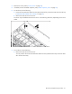
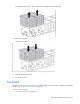
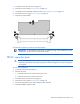
Table Of Contents
- HP ProLiant DL360p Gen8 Server Maintenance and Service Guide
- Abstract
- Notice
- Contents
- Customer self repair
- Illustrated parts catalog
- Removal and replacement procedures
- Required tools
- Preparation procedures
- Safety considerations
- Access panel
- Drive blank
- Hot-plug drive
- Power supply blank
- AC power supply
- 48V DC power supply option
- Drive cage assembly
- DVD-ROM or DVD-RW drive
- Fan module
- Fan blank
- Flash-backed write cache procedures
- Front video adapter
- FlexibleLOM
- Rack bezel
- Air baffle
- PCI riser cage
- Expansion boards
- PCIe riser board
- DIMMs
- Heatsink
- Processor
- System battery
- System board
- HP Trusted Platform Module
- Cabling
- Diagnostic tools
- Component identification
- Specifications
- Environmental specifications
- Server specifications
- Power supply specifications
- HP 460W Common Slot Gold Hot Plug Power Supply (92% efficiency)
- HP 460W Common Slot Platinum Plus Hot Plug Power Supply (94% efficiency)
- HP 500W Common Slot 277VAC Hot Plug Power Supply (94% efficiency)
- HP 750W Common Slot 277VAC Hot Plug Power Supply (94% efficiency)
- HP 750W Common Slot Titanium Hot Plug Power Supply (96% efficiency)
- HP 750W Common Slot Gold Hot Plug Power Supply (92% efficiency)
- HP 750W Common Slot Platinum Plus Hot Plug Power Supply (94% efficiency)
- HP 750W Common Slot -48VDC Hot Plug Power Supply (94% efficiency)
- HP 1200W Common Slot Platinum Plus Hot Plug Power Supply (94% efficiency)
- Hot-plug power supply calculations
- Acronyms and abbreviations
- Documentation feedback
- Index
Removal and replacement procedures 46
The server may look different than the one shown in the following illustration, depending on the server
model.
To replace the component, reverse the removal procedure.
Recovering data from the flash-backed write cache
If the server fails, use the following procedure to recover data temporarily stored in the FBWC.
CAUTION: Before starting this procedure, read the information about protecting against
electrostatic discharge ("Preventing electrostatic discharge" on page 28).
1. Perform one of the following:
o Set up a recovery server using an identical server model. Do not install any internal drives or FBWC
in this server. (HP recommends this option.)
o Find a server that has enough empty drive bays to accommodate all the drives from the failed server
and that meets all the other requirements for drive and array migration.
2. Power down the failed server ("Power down the server" on page 25).
3. Transfer the drives from the failed server to the recovery server.
4. Perform one of the following:
o If the array controller has failed, remove the cache module and capacitor pack from the failed array
controller, and install the cache module and capacitor pack on an identical array controller model
in the recovery server.
o If the server has failed, remove the controller, cache module, and capacitor pack from the failed
server, and install the controller, cache module, and capacitor pack in the recovery server.
5. Power up the recovery server. If there was data in the cache at the time of the controller or server failure,
a 1792 POST message appears, stating that valid data was flushed from the cache. This data is now
stored on the drives in the recovery server. You can now transfer the drives (and controller, if one is
used) to another server.
If the drives are migrated to different drive positions or there are volumes present in the recovery server,
a 1724 POST message appears, stating that logical drive configuration has been updated
automatically.