
HP ProLiant DL360p Gen8 Server Maintenance and Service Guide
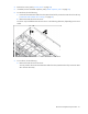
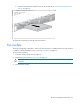
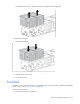
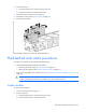
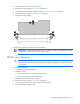
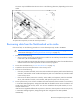
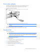
Table Of Contents
- HP ProLiant DL360p Gen8 Server Maintenance and Service Guide
- Abstract
- Notice
- Contents
- Customer self repair
- Illustrated parts catalog
- Removal and replacement procedures
- Required tools
- Preparation procedures
- Safety considerations
- Access panel
- Drive blank
- Hot-plug drive
- Power supply blank
- AC power supply
- 48V DC power supply option
- Drive cage assembly
- DVD-ROM or DVD-RW drive
- Fan module
- Fan blank
- Flash-backed write cache procedures
- Front video adapter
- FlexibleLOM
- Rack bezel
- Air baffle
- PCI riser cage
- Expansion boards
- PCIe riser board
- DIMMs
- Heatsink
- Processor
- System battery
- System board
- HP Trusted Platform Module
- Cabling
- Diagnostic tools
- Component identification
- Specifications
- Environmental specifications
- Server specifications
- Power supply specifications
- HP 460W Common Slot Gold Hot Plug Power Supply (92% efficiency)
- HP 460W Common Slot Platinum Plus Hot Plug Power Supply (94% efficiency)
- HP 500W Common Slot 277VAC Hot Plug Power Supply (94% efficiency)
- HP 750W Common Slot 277VAC Hot Plug Power Supply (94% efficiency)
- HP 750W Common Slot Titanium Hot Plug Power Supply (96% efficiency)
- HP 750W Common Slot Gold Hot Plug Power Supply (92% efficiency)
- HP 750W Common Slot Platinum Plus Hot Plug Power Supply (94% efficiency)
- HP 750W Common Slot -48VDC Hot Plug Power Supply (94% efficiency)
- HP 1200W Common Slot Platinum Plus Hot Plug Power Supply (94% efficiency)
- Hot-plug power supply calculations
- Acronyms and abbreviations
- Documentation feedback
- Index
Removal and replacement procedures 45
3.
Extend the server from the rack (on page 26).
4. Remove the access panel ("Access panel" on page 30).
5. If installed, remove the FBWC capacitor pack ("FBWC capacitor pack" on page 45).
6. Remove the PCI riser cage ("PCI riser cage" on page 50).
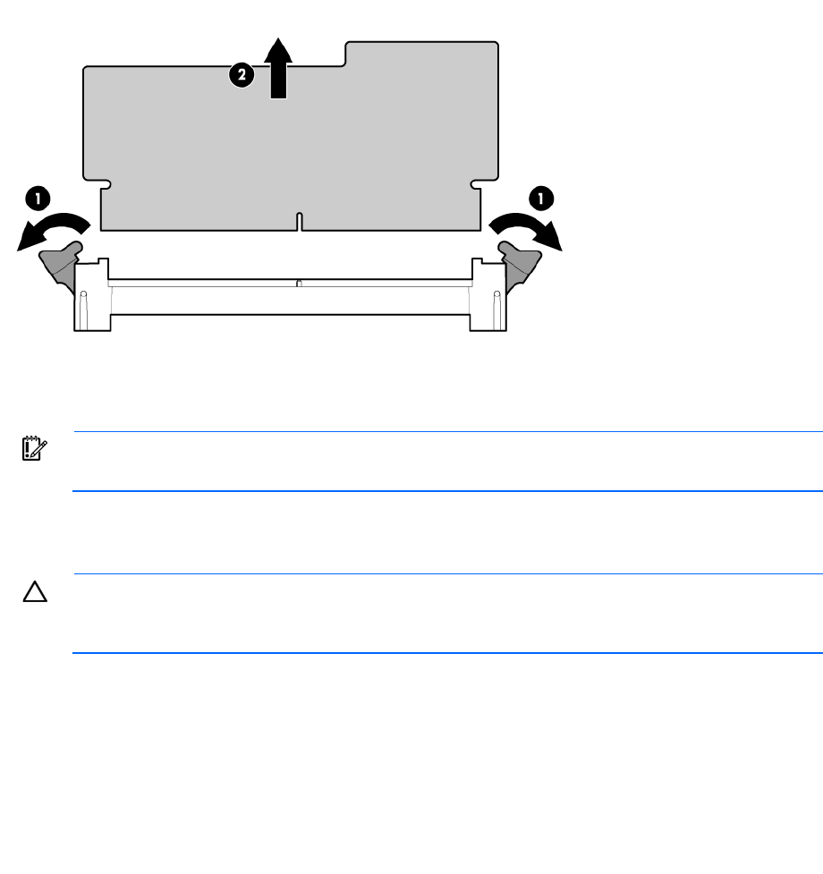
7. Remove the cache module.
To replace the component, reverse the removal procedure.
IMPORTANT: A cache module is required for a 10 SFF drive cage. Drives installed in a 10 SFF
configuration do not function without a cache module.
FBWC capacitor pack
CAUTION: To prevent a server malfunction or damage to the equipment, do not add or remove
the battery pack while an array capacity expansion, RAID level migration, or stripe size migration
is in progress.
To remove the component:
1. Power down the server (on page 25).
2. Remove all power:
a. Disconnect each power cord from the power source.
b. Disconnect each power cord from the server.
3. Extend the server from the rack (on page 26).
4. Remove the access panel ("Access panel" on page 30).
5. Disconnect the cable from the cache module or PCIe controller.
6. Remove the FBWC capacitor pack.