
HP ProLiant DL360p Gen8 Server Maintenance and Service Guide
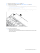
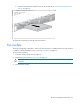
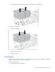
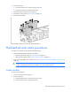
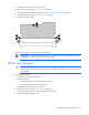
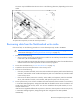
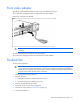
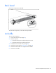
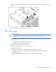
Table Of Contents
- HP ProLiant DL360p Gen8 Server Maintenance and Service Guide
- Abstract
- Notice
- Contents
- Customer self repair
- Illustrated parts catalog
- Removal and replacement procedures
- Required tools
- Preparation procedures
- Safety considerations
- Access panel
- Drive blank
- Hot-plug drive
- Power supply blank
- AC power supply
- 48V DC power supply option
- Drive cage assembly
- DVD-ROM or DVD-RW drive
- Fan module
- Fan blank
- Flash-backed write cache procedures
- Front video adapter
- FlexibleLOM
- Rack bezel
- Air baffle
- PCI riser cage
- Expansion boards
- PCIe riser board
- DIMMs
- Heatsink
- Processor
- System battery
- System board
- HP Trusted Platform Module
- Cabling
- Diagnostic tools
- Component identification
- Specifications
- Environmental specifications
- Server specifications
- Power supply specifications
- HP 460W Common Slot Gold Hot Plug Power Supply (92% efficiency)
- HP 460W Common Slot Platinum Plus Hot Plug Power Supply (94% efficiency)
- HP 500W Common Slot 277VAC Hot Plug Power Supply (94% efficiency)
- HP 750W Common Slot 277VAC Hot Plug Power Supply (94% efficiency)
- HP 750W Common Slot Titanium Hot Plug Power Supply (96% efficiency)
- HP 750W Common Slot Gold Hot Plug Power Supply (92% efficiency)
- HP 750W Common Slot Platinum Plus Hot Plug Power Supply (94% efficiency)
- HP 750W Common Slot -48VDC Hot Plug Power Supply (94% efficiency)
- HP 1200W Common Slot Platinum Plus Hot Plug Power Supply (94% efficiency)
- Hot-plug power supply calculations
- Acronyms and abbreviations
- Documentation feedback
- Index
Removal and replacement procedures 50
The server may look different than the one shown in the following illustration, depending on the server
model.
To replace the component, reverse the removal procedure.
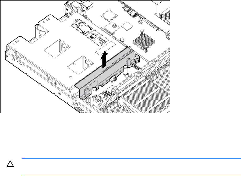
PCI riser cage
To remove the component:
CAUTION: To prevent damage to the server or expansion boards, power down the server and
remove all AC power cords before removing or installing the PCI riser cage.
1. Power down the server (on page 25).
2. Remove all power:
a. Disconnect each power cord from the power source.
b. Disconnect each power cord from the server.
3. Extend the server from the rack (on page 26).
4. Remove the access panel ("Access panel" on page 30).
5. Remove the PCI riser cage:
a. Disconnect external cables connected to any existing expansion boards.
b. Disengage the two PCI riser cage thumbscrews. Lift the tab, rotate 180 degrees, and the
thumbscrew pops up.
c. Lift the assembly to unseat the PCI riser boards, and then remove the cage.