
HP ProLiant DL360p Gen8 Server Maintenance and Service Guide
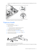
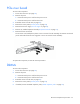
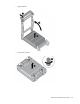
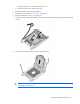
Table Of Contents
- HP ProLiant DL360p Gen8 Server Maintenance and Service Guide
- Abstract
- Notice
- Contents
- Customer self repair
- Illustrated parts catalog
- Removal and replacement procedures
- Required tools
- Preparation procedures
- Safety considerations
- Access panel
- Drive blank
- Hot-plug drive
- Power supply blank
- AC power supply
- 48V DC power supply option
- Drive cage assembly
- DVD-ROM or DVD-RW drive
- Fan module
- Fan blank
- Flash-backed write cache procedures
- Front video adapter
- FlexibleLOM
- Rack bezel
- Air baffle
- PCI riser cage
- Expansion boards
- PCIe riser board
- DIMMs
- Heatsink
- Processor
- System battery
- System board
- HP Trusted Platform Module
- Cabling
- Diagnostic tools
- Component identification
- Specifications
- Environmental specifications
- Server specifications
- Power supply specifications
- HP 460W Common Slot Gold Hot Plug Power Supply (92% efficiency)
- HP 460W Common Slot Platinum Plus Hot Plug Power Supply (94% efficiency)
- HP 500W Common Slot 277VAC Hot Plug Power Supply (94% efficiency)
- HP 750W Common Slot 277VAC Hot Plug Power Supply (94% efficiency)
- HP 750W Common Slot Titanium Hot Plug Power Supply (96% efficiency)
- HP 750W Common Slot Gold Hot Plug Power Supply (92% efficiency)
- HP 750W Common Slot Platinum Plus Hot Plug Power Supply (94% efficiency)
- HP 750W Common Slot -48VDC Hot Plug Power Supply (94% efficiency)
- HP 1200W Common Slot Platinum Plus Hot Plug Power Supply (94% efficiency)
- Hot-plug power supply calculations
- Acronyms and abbreviations
- Documentation feedback
- Index

Removal and replacement procedures 58
To replace the component:
1. Install the processor. Verify that the processor is fully seated in the processor retaining bracket by
visually inspecting the processor installation guides on either side of the processor. THE PINS ON THE
SYSTEM BOARD ARE VERY FRAGILE AND EASILY DAMAGED.
CAUTION: THE PINS ON THE SYSTEM BOARD ARE VERY FRAGILE AND EASILY DAMAGED. To
avoid damage to the system board, do not touch the processor or the processor socket contacts.
2. Close the processor retaining bracket. When the processor is installed properly inside the processor
retaining bracket, the processor retaining bracket clears the flange on the front of the socket.
CAUTION: Do not press down on the processor. Pressing down on the processor may cause
damage to the processor socket and the system board. Press only in the area indicated on the
processor retaining bracket.