
HP ProLiant DL360p Gen8 Server Maintenance and Service Guide
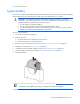
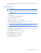
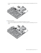
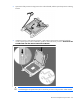
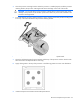
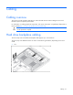
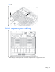
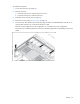
Table Of Contents
- HP ProLiant DL360p Gen8 Server Maintenance and Service Guide
- Abstract
- Notice
- Contents
- Customer self repair
- Illustrated parts catalog
- Removal and replacement procedures
- Required tools
- Preparation procedures
- Safety considerations
- Access panel
- Drive blank
- Hot-plug drive
- Power supply blank
- AC power supply
- 48V DC power supply option
- Drive cage assembly
- DVD-ROM or DVD-RW drive
- Fan module
- Fan blank
- Flash-backed write cache procedures
- Front video adapter
- FlexibleLOM
- Rack bezel
- Air baffle
- PCI riser cage
- Expansion boards
- PCIe riser board
- DIMMs
- Heatsink
- Processor
- System battery
- System board
- HP Trusted Platform Module
- Cabling
- Diagnostic tools
- Component identification
- Specifications
- Environmental specifications
- Server specifications
- Power supply specifications
- HP 460W Common Slot Gold Hot Plug Power Supply (92% efficiency)
- HP 460W Common Slot Platinum Plus Hot Plug Power Supply (94% efficiency)
- HP 500W Common Slot 277VAC Hot Plug Power Supply (94% efficiency)
- HP 750W Common Slot 277VAC Hot Plug Power Supply (94% efficiency)
- HP 750W Common Slot Titanium Hot Plug Power Supply (96% efficiency)
- HP 750W Common Slot Gold Hot Plug Power Supply (92% efficiency)
- HP 750W Common Slot Platinum Plus Hot Plug Power Supply (94% efficiency)
- HP 750W Common Slot -48VDC Hot Plug Power Supply (94% efficiency)
- HP 1200W Common Slot Platinum Plus Hot Plug Power Supply (94% efficiency)
- Hot-plug power supply calculations
- Acronyms and abbreviations
- Documentation feedback
- Index
Removal and replacement procedures 62
For more information about battery replacement or proper disposal, contact an authorized reseller or an
authorized service provider.
System board
To remove the component:
IMPORTANT: Be sure you are using the correct spare part. The HP ProLiant DL360p Gen8 Server
ships with one of two different system boards that each use specific processors and heatsinks. To
identify the proper system board spare part number, see the white label on the system board that
shipped with the server.
1. Power down the server (on page 25).
2. Remove all power:
a. Disconnect each power cord from the power source.
b. Disconnect each power cord from the server.
3. Remove the server from the rack.
4. Remove the access panel ("Access panel" on page 30).
5. Remove all power supplies ("AC power supply" on page 32).
6. If installed, remove the FBWC capacitor pack ("FBWC capacitor pack" on page 45).
7. Remove the air baffle ("Air baffle" on page 49).
CAUTION: To prevent damage to the server or expansion boards, power down the server and
remove all AC power cords before removing or installing the PCI riser cage.
8. Remove the PCI riser cage ("PCI riser cage" on page 50).
9. Remove the fans ("Fan module" on page 42).
10. Disconnect all cables connected to the system board ("System board components" on page 81). For
more information, see "Cabling (on page 67)."
11. Remove the cache module ("Cache module" on page 44).
12. Remove the FlexibleLOM ("FlexibleLOM" on page 47).
13. Remove all DIMMs ("DIMMs" on page 52).
14. Remove the heatsink ("Heatsink" on page 53).
15. Remove the processor ("Processor" on page 56).
16. Remove the failed system board.