
HP ProLiant DL360p Gen8 Server Maintenance and Service Guide
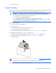
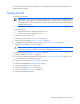
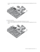
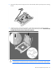
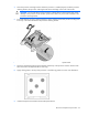
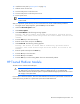
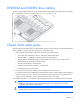
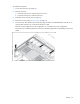
Table Of Contents
- HP ProLiant DL360p Gen8 Server Maintenance and Service Guide
- Abstract
- Notice
- Contents
- Customer self repair
- Illustrated parts catalog
- Removal and replacement procedures
- Required tools
- Preparation procedures
- Safety considerations
- Access panel
- Drive blank
- Hot-plug drive
- Power supply blank
- AC power supply
- 48V DC power supply option
- Drive cage assembly
- DVD-ROM or DVD-RW drive
- Fan module
- Fan blank
- Flash-backed write cache procedures
- Front video adapter
- FlexibleLOM
- Rack bezel
- Air baffle
- PCI riser cage
- Expansion boards
- PCIe riser board
- DIMMs
- Heatsink
- Processor
- System battery
- System board
- HP Trusted Platform Module
- Cabling
- Diagnostic tools
- Component identification
- Specifications
- Environmental specifications
- Server specifications
- Power supply specifications
- HP 460W Common Slot Gold Hot Plug Power Supply (92% efficiency)
- HP 460W Common Slot Platinum Plus Hot Plug Power Supply (94% efficiency)
- HP 500W Common Slot 277VAC Hot Plug Power Supply (94% efficiency)
- HP 750W Common Slot 277VAC Hot Plug Power Supply (94% efficiency)
- HP 750W Common Slot Titanium Hot Plug Power Supply (96% efficiency)
- HP 750W Common Slot Gold Hot Plug Power Supply (92% efficiency)
- HP 750W Common Slot Platinum Plus Hot Plug Power Supply (94% efficiency)
- HP 750W Common Slot -48VDC Hot Plug Power Supply (94% efficiency)
- HP 1200W Common Slot Platinum Plus Hot Plug Power Supply (94% efficiency)
- Hot-plug power supply calculations
- Acronyms and abbreviations
- Documentation feedback
- Index

Removal and replacement procedures 65
4.
Close the processor retaining bracket. When the processor is installed properly inside the processor
retaining bracket, the processor retaining bracket clears the flange on the front of the socket.
CAUTION: Do not press down on the processor. Pressing down on the processor may cause
damage to the processor socket and the system board. Press only in the area indicated on the
processor retaining bracket.
5. Press and hold the processor retaining bracket in place, and then close each processor locking lever.
Press only in the area indicated on the processor retaining bracket.
6. Install the processor socket cover onto the processor socket of the failed system board.
7. Clean the old thermal grease from the heatsink and the top of the processor with the alcohol swab.
Allow the alcohol to evaporate before continuing.
8. Apply all the grease to the top of the processor in the following pattern to ensure even distribution.
9. Install all components removed from the failed system board.