
HP ProLiant DL360p Gen8 Server Maintenance and Service Guide
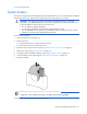
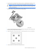
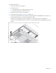
Table Of Contents
- HP ProLiant DL360p Gen8 Server Maintenance and Service Guide
- Abstract
- Notice
- Contents
- Customer self repair
- Illustrated parts catalog
- Removal and replacement procedures
- Required tools
- Preparation procedures
- Safety considerations
- Access panel
- Drive blank
- Hot-plug drive
- Power supply blank
- AC power supply
- 48V DC power supply option
- Drive cage assembly
- DVD-ROM or DVD-RW drive
- Fan module
- Fan blank
- Flash-backed write cache procedures
- Front video adapter
- FlexibleLOM
- Rack bezel
- Air baffle
- PCI riser cage
- Expansion boards
- PCIe riser board
- DIMMs
- Heatsink
- Processor
- System battery
- System board
- HP Trusted Platform Module
- Cabling
- Diagnostic tools
- Component identification
- Specifications
- Environmental specifications
- Server specifications
- Power supply specifications
- HP 460W Common Slot Gold Hot Plug Power Supply (92% efficiency)
- HP 460W Common Slot Platinum Plus Hot Plug Power Supply (94% efficiency)
- HP 500W Common Slot 277VAC Hot Plug Power Supply (94% efficiency)
- HP 750W Common Slot 277VAC Hot Plug Power Supply (94% efficiency)
- HP 750W Common Slot Titanium Hot Plug Power Supply (96% efficiency)
- HP 750W Common Slot Gold Hot Plug Power Supply (92% efficiency)
- HP 750W Common Slot Platinum Plus Hot Plug Power Supply (94% efficiency)
- HP 750W Common Slot -48VDC Hot Plug Power Supply (94% efficiency)
- HP 1200W Common Slot Platinum Plus Hot Plug Power Supply (94% efficiency)
- Hot-plug power supply calculations
- Acronyms and abbreviations
- Documentation feedback
- Index
Removal and replacement procedures 66
10. Install the access panel ("Access panel" on page 30).
11. Slide the server into the rack.
12. Connect each power cord to the server.
13. Connect each power cord to the power source.
14. Power up the server.
IMPORTANT: Install all components with the same configuration that was used on the failed
system board.
After you replace the system board, you must re-enter the server serial number and the product ID.
1. During the server startup sequence, press the F9 key to access RBSU.
2. Select the Advanced Options menu.
3. Select Service Options.
4. Select Serial Number. The following warning appears:
Warning: The serial number should ONLY be modified by qualified service
personnel. This value should always match the serial number located on the
chassis.
5. Press the Enter key to clear the warning.
6. Enter the serial number and press the Enter key.
7. Select Product ID. The following warning appears:
Warning: The Product ID should ONLY be modified by qualified service
personnel. This value should always match the Product ID located on the
chassis.
8. Enter the product ID and press the Enter key.
9. Press the Esc key to close the menu.
10. Press the Esc key to exit RBSU.
11. Press the F10 key to confirm exiting RBSU. The server automatically reboots.
HP Trusted Platform Module
The TPM is not a customer-removable part.
CAUTION:
Any attempt to remove an installed TPM from the system board breaks or disfigures
the TPM security rivet. Upon locating a broken or disfigured rivet on an installed TPM,
administrators should consider the system compromised and take appropriate measures to ensure
the integrity of the system data.
If you suspect a TPM board failure, leave the TPM installed and remove the system board. Contact an HP
authorized service provider for a replacement system board and TPM board.