
HP ProLiant DL360p Gen8 Server Maintenance and Service Guide
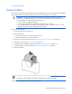
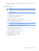
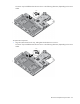
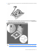
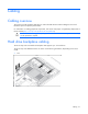
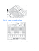
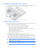
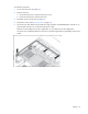
Table Of Contents
- HP ProLiant DL360p Gen8 Server Maintenance and Service Guide
- Abstract
- Notice
- Contents
- Customer self repair
- Illustrated parts catalog
- Removal and replacement procedures
- Required tools
- Preparation procedures
- Safety considerations
- Access panel
- Drive blank
- Hot-plug drive
- Power supply blank
- AC power supply
- 48V DC power supply option
- Drive cage assembly
- DVD-ROM or DVD-RW drive
- Fan module
- Fan blank
- Flash-backed write cache procedures
- Front video adapter
- FlexibleLOM
- Rack bezel
- Air baffle
- PCI riser cage
- Expansion boards
- PCIe riser board
- DIMMs
- Heatsink
- Processor
- System battery
- System board
- HP Trusted Platform Module
- Cabling
- Diagnostic tools
- Component identification
- Specifications
- Environmental specifications
- Server specifications
- Power supply specifications
- HP 460W Common Slot Gold Hot Plug Power Supply (92% efficiency)
- HP 460W Common Slot Platinum Plus Hot Plug Power Supply (94% efficiency)
- HP 500W Common Slot 277VAC Hot Plug Power Supply (94% efficiency)
- HP 750W Common Slot 277VAC Hot Plug Power Supply (94% efficiency)
- HP 750W Common Slot Titanium Hot Plug Power Supply (96% efficiency)
- HP 750W Common Slot Gold Hot Plug Power Supply (92% efficiency)
- HP 750W Common Slot Platinum Plus Hot Plug Power Supply (94% efficiency)
- HP 750W Common Slot -48VDC Hot Plug Power Supply (94% efficiency)
- HP 1200W Common Slot Platinum Plus Hot Plug Power Supply (94% efficiency)
- Hot-plug power supply calculations
- Acronyms and abbreviations
- Documentation feedback
- Index
Cabling 69
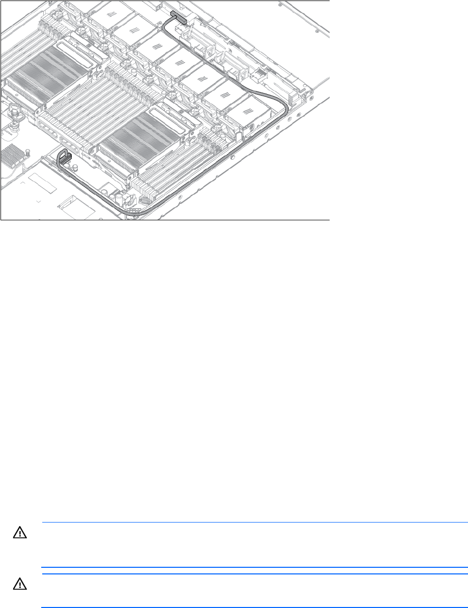
DVD-ROM and DVD-RW drive cabling
The server may look different than the one shown in the following illustration, depending on the server model.
Chipset SATA cable option
With the chipset SATA cable option, the chipset SATA controller can be used with a single SATA hard drive
that is installed in one hard drive bay of the SFF or LFF hard drive cage.
• When using the chipset SATA configuration, the following conditions apply:
o The 10 SFF drive configuration does not support the chipset SATA option.
o Only drive bay 1 is enabled. The remaining drive bays are disabled.
o The optical bay is disabled because the chipset SATA controller port on the system board is
redirected from the optical bay to the drive cage.
o Hard drive status LEDs are not supported.
o Hard drive thermal status monitoring is not supported.
o Hot-plug operation is not supported.
• Because only one drive bay is enabled, all remaining drives can be removed.
For proper thermal cooling, install blanks in all bays that do not have a drive installed. Order a sufficient
number of 6.35-cm (2.5-in) or 8.89-cm (3.5-in) hard drive blank option kits from an HP authorized
reseller. For more information, see the server maintenance and service guide.
The standard SATA driver is included with supported operating systems. No additional driver is required.
WARNING: Eliminate the risk of electric shock by removing all AC power from the system before
installing or replacing any non-hot-plug hardware option. Disconnect all power cords to
completely remove power from the server.
WARNING: To reduce the risk of personal injury from hot surfaces, allow the drives and the
internal system components to cool before touching them.