
HP ProLiant DL360p Gen8 Server Maintenance and Service Guide
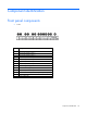
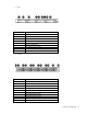
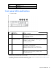
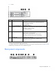
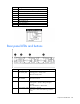
Table Of Contents
- HP ProLiant DL360p Gen8 Server Maintenance and Service Guide
- Abstract
- Notice
- Contents
- Customer self repair
- Illustrated parts catalog
- Removal and replacement procedures
- Required tools
- Preparation procedures
- Safety considerations
- Access panel
- Drive blank
- Hot-plug drive
- Power supply blank
- AC power supply
- 48V DC power supply option
- Drive cage assembly
- DVD-ROM or DVD-RW drive
- Fan module
- Fan blank
- Flash-backed write cache procedures
- Front video adapter
- FlexibleLOM
- Rack bezel
- Air baffle
- PCI riser cage
- Expansion boards
- PCIe riser board
- DIMMs
- Heatsink
- Processor
- System battery
- System board
- HP Trusted Platform Module
- Cabling
- Diagnostic tools
- Component identification
- Specifications
- Environmental specifications
- Server specifications
- Power supply specifications
- HP 460W Common Slot Gold Hot Plug Power Supply (92% efficiency)
- HP 460W Common Slot Platinum Plus Hot Plug Power Supply (94% efficiency)
- HP 500W Common Slot 277VAC Hot Plug Power Supply (94% efficiency)
- HP 750W Common Slot 277VAC Hot Plug Power Supply (94% efficiency)
- HP 750W Common Slot Titanium Hot Plug Power Supply (96% efficiency)
- HP 750W Common Slot Gold Hot Plug Power Supply (92% efficiency)
- HP 750W Common Slot Platinum Plus Hot Plug Power Supply (94% efficiency)
- HP 750W Common Slot -48VDC Hot Plug Power Supply (94% efficiency)
- HP 1200W Common Slot Platinum Plus Hot Plug Power Supply (94% efficiency)
- Hot-plug power supply calculations
- Acronyms and abbreviations
- Documentation feedback
- Index
Component identification 78
Item Description
11
Systems Insight Display
12
USB connector
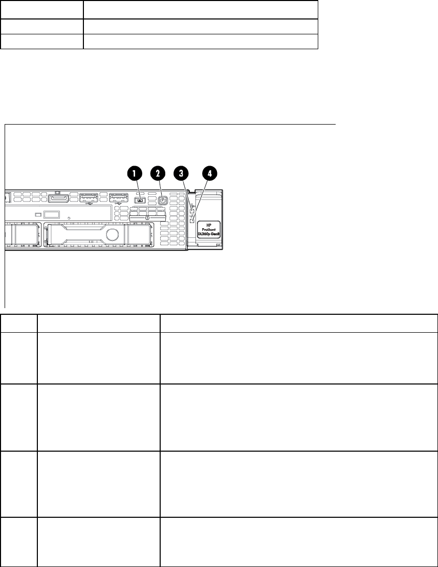
Front panel LEDs and buttons
• 8 SFF or 4 LFF
Item Description Status
1
UID button/LED Solid blue = Activated
Flashing blue (1 Hz/cycle per sec) = Remote management or
firmware upgrade in progress
Off = Deactivated
2
Power On/Standby button
and system power LED
Solid green = System on
Flashing green (1 Hz/cycle per sec) = Performing power on sequence
Solid amber = System in standby
Off = No power present*
3
Health LED Solid green = Normal
Flashing amber = System degraded
Flashing red (1 Hz/cycle per sec) = System critical
Fast-flashing red (4 Hz/cycles per sec) = Power fault**
4
NIC status LED Solid green = Link to network
Flashing green (1 Hz/cycle per sec) = Network active
Off = No network activity
*Facility power is not present, power cord is not attached, no power supplies are installed, power supply failure has
occurred, or the power button cable is disconnected.
**To identify components in a degraded or critical state, see the Systems Insight Display LEDs (on page 84), check
iLO/BIOS logs, and reference the server troubleshooting guide.