
HP ProLiant DL360p Gen8 Server Maintenance and Service Guide
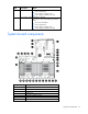
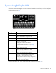
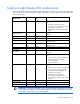
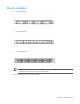

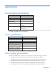
Table Of Contents
- HP ProLiant DL360p Gen8 Server Maintenance and Service Guide
- Abstract
- Notice
- Contents
- Customer self repair
- Illustrated parts catalog
- Removal and replacement procedures
- Required tools
- Preparation procedures
- Safety considerations
- Access panel
- Drive blank
- Hot-plug drive
- Power supply blank
- AC power supply
- 48V DC power supply option
- Drive cage assembly
- DVD-ROM or DVD-RW drive
- Fan module
- Fan blank
- Flash-backed write cache procedures
- Front video adapter
- FlexibleLOM
- Rack bezel
- Air baffle
- PCI riser cage
- Expansion boards
- PCIe riser board
- DIMMs
- Heatsink
- Processor
- System battery
- System board
- HP Trusted Platform Module
- Cabling
- Diagnostic tools
- Component identification
- Specifications
- Environmental specifications
- Server specifications
- Power supply specifications
- HP 460W Common Slot Gold Hot Plug Power Supply (92% efficiency)
- HP 460W Common Slot Platinum Plus Hot Plug Power Supply (94% efficiency)
- HP 500W Common Slot 277VAC Hot Plug Power Supply (94% efficiency)
- HP 750W Common Slot 277VAC Hot Plug Power Supply (94% efficiency)
- HP 750W Common Slot Titanium Hot Plug Power Supply (96% efficiency)
- HP 750W Common Slot Gold Hot Plug Power Supply (92% efficiency)
- HP 750W Common Slot Platinum Plus Hot Plug Power Supply (94% efficiency)
- HP 750W Common Slot -48VDC Hot Plug Power Supply (94% efficiency)
- HP 1200W Common Slot Platinum Plus Hot Plug Power Supply (94% efficiency)
- Hot-plug power supply calculations
- Acronyms and abbreviations
- Documentation feedback
- Index

Component identification 82
Item Description
8
SAS connector B (Drives 5–8)
9
SAS connector A (drives 1–4)
10
NMI jumper
11
System maintenance switch
12
Processor 1
13
Fan module 8 connector
14
Processor 1 DIMM slots
15
Fan module 7 connector
16
Fan module 6 connector
17
Fan module 5 connector
18
Processor 1 DIMM slots
19
Fan module 4 connector
20
Processor 2 DIMM slots
21
Fan module 3 connector
22
Fan module 2 connector
23
Fan module 1 connector
24
Processor 2 DIMM slots
25
Processor 2
26
Drive backplane power connector
27
Internal USB connector
28
Power supply connector 1
29
SD card slot
30
Power supply connector 2
31
Optical SATA connector
DIMM slots
DIMM slots are numbered sequentially (1 through 12) for each processor. The supported AMP modes use the
letter assignments for population guidelines.