
HP ProLiant DL360p Gen8 Server Maintenance and Service Guide
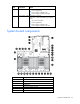
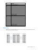
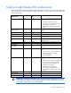

Table Of Contents
- HP ProLiant DL360p Gen8 Server Maintenance and Service Guide
- Abstract
- Notice
- Contents
- Customer self repair
- Illustrated parts catalog
- Removal and replacement procedures
- Required tools
- Preparation procedures
- Safety considerations
- Access panel
- Drive blank
- Hot-plug drive
- Power supply blank
- AC power supply
- 48V DC power supply option
- Drive cage assembly
- DVD-ROM or DVD-RW drive
- Fan module
- Fan blank
- Flash-backed write cache procedures
- Front video adapter
- FlexibleLOM
- Rack bezel
- Air baffle
- PCI riser cage
- Expansion boards
- PCIe riser board
- DIMMs
- Heatsink
- Processor
- System battery
- System board
- HP Trusted Platform Module
- Cabling
- Diagnostic tools
- Component identification
- Specifications
- Environmental specifications
- Server specifications
- Power supply specifications
- HP 460W Common Slot Gold Hot Plug Power Supply (92% efficiency)
- HP 460W Common Slot Platinum Plus Hot Plug Power Supply (94% efficiency)
- HP 500W Common Slot 277VAC Hot Plug Power Supply (94% efficiency)
- HP 750W Common Slot 277VAC Hot Plug Power Supply (94% efficiency)
- HP 750W Common Slot Titanium Hot Plug Power Supply (96% efficiency)
- HP 750W Common Slot Gold Hot Plug Power Supply (92% efficiency)
- HP 750W Common Slot Platinum Plus Hot Plug Power Supply (94% efficiency)
- HP 750W Common Slot -48VDC Hot Plug Power Supply (94% efficiency)
- HP 1200W Common Slot Platinum Plus Hot Plug Power Supply (94% efficiency)
- Hot-plug power supply calculations
- Acronyms and abbreviations
- Documentation feedback
- Index
Component identification 83
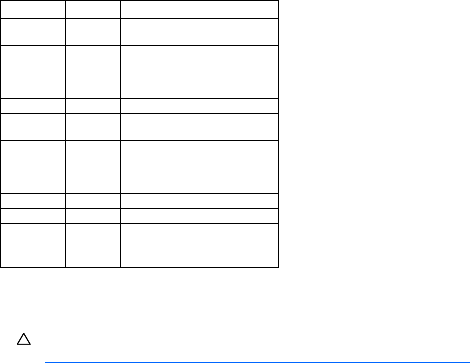
System maintenance switch
Position Default Function
S1
Off Off = HP iLO security is enabled.
On = HP iLO security is disabled.
S2
Off Off = System configuration can be
changed.
On = System configuration is locked.
S3
Off Reserved
S4
Off Reserved
S5
Off Off = Power-on password is enabled.
On = Power-on password is disabled.
S6
Off Off = No function
On = ROM reads system configuration
as invalid.
S7
— Reserved
S8
— Reserved
S9
— Reserved
S10
— Reserved
S11
— Reserved
S12
— Reserved
To access the redundant ROM, set S1, S5, and S6 to on.
When the system maintenance switch position 6 is set to the On position, the system is prepared to erase all
system configuration settings from both CMOS and NVRAM.
CAUTION: Clearing CMOS and/or NVRAM deletes configuration information. Be sure to
properly configure the server or data loss could occur.
NMI jumper
The NMI jumper allows administrators to perform a memory dump before performing a hard reset. Crash
dump analysis is an essential part of eliminating reliability problems, such as hangs or crashes in OSs, device
drivers, and applications. Many crashes can freeze a system, requiring you to do a hard reset. Resetting the
system erases any information that would support root cause analysis.
Systems running Microsoft® Windows® experience a blue-screen trap when the OS crashes. When this
happens, Microsoft® recommends that system administrators perform an NMI event by temporarily shorting
the NMI header with a jumper. The NMI event enables a hung system to become responsive again.