HP ProLiant DL365 Server User Guide Second Edition (October 2006) Part Number 418292-002
© Copyright 2006 Hewlett-Packard Development Company, L.P. The information contained herein is subject to change without notice. The only warranties for HP products and services are set forth in the express warranty statements accompanying such products and services. Nothing herein should be construed as constituting an additional warranty. HP shall not be liable for technical or editorial errors or omissions contained herein. Microsoft, Windows, and Windows NT are U.S.
Contents Component identification ............................................................................................................... 7 Front panel components ............................................................................................................................. 7 Front panel LEDs and buttons ...................................................................................................................... 8 Rear panel components.........................................
Removing hard drive blanks............................................................................................................ 39 Removing hard drive bezel blanks ................................................................................................... 39 Removing a hot-plug SAS or SATA hard drive ................................................................................... 40 Installing a hot-plug SAS or SATA hard drive ...............................................................
Open Services Event Manager ........................................................................................................ 74 Keeping the system current ....................................................................................................................... 74 Drivers ......................................................................................................................................... 74 Resource Paqs................................................................
Server specifications .............................................................................................................................. 100 Technical support...................................................................................................................... 102 Related documents ................................................................................................................................ 102 HP contact information ............................................
Component identification In this section Front panel components ............................................................................................................................ 7 Front panel LEDs and buttons ..................................................................................................................... 8 Rear panel components.............................................................................................................................
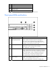
Item Description 8 Hard drive bay 3 9 Hard drive bay 2 10 Hard drive bay 1 11 Serial pull tab *An optional controller is required when the server is configured with six hard drives. Front panel LEDs and buttons Item Description Status 1 Power On/Standby button and system power LED Green = System is on. Amber = System is shut down, but power is still applied.
Item Description Status 5 NIC 1 link/activity LED Green = Network link exists. Flashing green = Network link and activity exist. Off = No link to network exists. If power is off, the front panel LED is not active. View the LEDs on the RJ-45 connector for status by referring to the rear panel LEDs ("Rear panel LEDs and buttons" on page 10). 6 NIC 2 link/activity LED Green = Network link exists. Flashing green = Network link and activity exist. Off = No link to network exists.
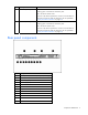
Item Description 13 iLO 2 NIC connector Rear panel LEDs and buttons Item Description Status 1 iLO 2 NIC activity LED Green = Activity exists. Flashing green = Activity exists. Off = No activity exists. 2 3 iLO 2 NIC link LED Green = Link exists. 10/100/1000 Green = Activity exists. NIC 1 activity LED Flashing green = Activity exists. Off = No link exists. Off = No activity exists. 4 5 10/100/1000 Green = Link exists. NIC 1 link LED Off = No link exists.
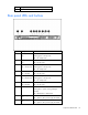
System board components Item Description 1 System battery 2 NMI jumper 3 System maintenance switch (SW1) 4 Internal USB connector 5 Multibay connector 6 Power switch connector 7 DIMM slots (1-4) 8 Fan module 3 connectors 9 Fan module 2 connectors 10 DIMM slots (5-8) 11 Fan module 1 connectors 12 SFF hard drive backplane power connector 13 Integrated Smart Array controller connector 14 Power supply connector 1 15 Power supply connector 2 16 Processor socket 2 17 Processor
System maintenance switch Position Default Function S1 Off Off = iLO 2 security is enabled. On = iLO 2 security is disabled. S2 Off Off = System configuration can be modified. On = System configuration is locked and cannot be modified. S3 Off Reserved S4 Off Reserved S5 Off Off = Power-on password is enabled. On = Power-on password is disabled. S6 Off Off = Normal On = ROM treats system configuration as invalid.
To view the LEDs, access the HP Systems Insight Display (on page 18). LED Status Off Normal Amber Failure For additional information about these LEDs, see "HP Systems Insight Display LEDs and internal health LED combinations (on page 13)." NOTE: The HP Systems Insight Display LEDs represent the system board layout.
HP Systems Insight Display LED and color Internal health LED color Status DIMM failure, slot X (amber) Red One or more of the following conditions may exist: Amber • DIMM in slot X has failed. • DIMM in slot X is an unsupported type, and no valid memory exists in another bank. One or more of the following conditions may exist: • DIMM in slot X has reached single-bit correctable error threshold. • DIMM in slot X is in a pre-failure condition.
Six hard drive configuration • SAS and SATA hard drive LEDs Item Description 1 Fault/UID LED (amber/blue) 2 Online LED (green) SAS and SATA hard drive LED combinations Online/activity LED Fault/UID LED (green) (amber/blue) Interpretation On, off, or flashing Alternating amber and blue The drive has failed, or a predictive failure alert has been received for this drive; it also has been selected by a management application.
Online/activity LED Fault/UID LED (green) (amber/blue) Interpretation On, off, or flashing Steadily blue The drive is operating normally, and it has been selected by a management application. On Amber, flashing regularly (1 Hz) A predictive failure alert has been received for this drive. Replace the drive as soon as possible. On Off The drive is online, but it is not active currently. Flashing regularly (1 Hz) Amber, flashing regularly (1 Hz) Do not remove the drive.
Item Description 1 Fan module 1 2 Fan module 2 3 Fan module 3 Component identification 17
Operations In this section Power up the server ................................................................................................................................ 18 Power down the server............................................................................................................................ 18 Access the HP Systems Insight Display ...................................................................................................... 18 Extend the server from the rack ........
2. Extend the display from the chassis. The display can be rotated up to 90 degrees. Extend the server from the rack NOTE: If the optional cable management arm option is installed, you can extend the server without powering down the server or disconnecting peripheral cables and power cords. These steps are only necessary with the standard cable management solution. 1. Power down the server (on page 18). 2. Disconnect all peripheral cables and power cords. 3. Loosen the front panel thumbscrews. 4.
WARNING: To reduce the risk of personal injury, be careful when pressing the server rail-release latches and sliding the server into the rack. The sliding rails could pinch your fingers. 5. After performing the installation or maintenance procedure, slide the server into the rack: a. Slide the server fully into the rack. b. Secure the server by tightening the thumbscrews. 6. Connect the peripheral cables and power cords.
4. Remove the air baffle. To install the component, reverse the removal procedure. Remove the PCI riser board assembly CAUTION: To prevent damage to the server or expansion boards, power down the server and remove all AC power cords before removing or installing the PCI riser board assembly. 1. Power down the server (on page 18). 2. Extend or remove the server from the rack ("Extend the server from the rack" on page 19). 3. Remove the access panel (on page 20). 4.
To replace the component, reverse the removal procedure. Install the PCI riser board assembly CAUTION: To prevent damage to the server or expansion boards, power down the server and remove all AC power cords before removing or installing the PCI riser board assembly. 1. Align the PCI riser boards with the corresponding connectors on the system board and install the assembly. 2. Tighten the four PCI riser board assembly thumbscrews. Remove and install a fan module The server has three fan modules.
5. Remove a fan module. To install a fan module, reverse the removal procedures. IMPORTANT: After installing the fan module, firmly press the top of the module connectors to ensure the connectors are seated properly.
Setup In this section Optional installation services ................................................................................................................... 24 Rack planning resources ......................................................................................................................... 25 Optimum environment............................................................................................................................. 25 Rack warnings .............................
Rack planning resources The rack resource kit ships with all HP branded or Compaq branded 9000, 10000, and H9 series racks. For more information on the content of each resource, refer to the rack resource kit documentation. If you intend to deploy and configure multiple servers in a single rack, refer to the white paper on highdensity deployment at the HP website (http://www.hp.com/products/servers/platforms).
Temperature requirements To ensure continued safe and reliable equipment operation, install or position the system in a wellventilated, climate-controlled environment. The maximum recommended ambient operating temperature (TMRA) for most server products is 35°C (95°F). The temperature in the room where the rack is located must not exceed 35°C (95°F).
circuit or includes a nondetachable cord that is wired to an industrial-style plug. NEMA locking-style plugs or those complying with IEC 60309 are considered suitable for this purpose. Using common power outlet strips for the server is not recommended. Rack warnings WARNING: To reduce the risk of personal injury or damage to the equipment, be sure that: • The leveling jacks are extended to the floor. • The full weight of the rack rests on the leveling jacks.
Installing the server into the rack To install the server into a rack with square, round, or threaded holes, refer to the instructions that ship with the rack hardware kit. If you are installing the server into a telco rack, order the appropriate option kit at the RackSolutions.com website (http://www.racksolutions.com/hp). Follow the server-specific instructions on the website to install the rack brackets. Use the following information when connecting peripheral cables and power cords to the server.
Item Description 6 NIC 1 connector 7 Keyboard connector 8 Mouse connector 9 Video connector 10 Serial connector 11 USB connector 12 USB connector 13 iLO 2 NIC connector 3. Use the strain relief clip from the server hardware kit to secure the power cord. Powering up and configuring the server To power up the server, press the Power On/Standby button. While the server boots, RBSU and the ORCA utility are automatically configured to prepare the server for operating system installation.
• SmartStart assisted installation—Insert the SmartStart CD into the CD-ROM drive and reboot the server. • Manual installation—Insert the operating system CD into the CD-ROM drive and reboot the server. This process may require you to obtain additional drivers from the HP website (http://www.hp.com/support). Follow the on-screen instructions to begin the installation process.
Hardware options installation In this section Introduction ........................................................................................................................................... 31 Processor option..................................................................................................................................... 31 Memory options .....................................................................................................................................
CAUTION: To help avoid damage to the processor and system board, do not install the processor without using the processor installation tool. CAUTION: To prevent possible server malfunction, do not mix processors of different speeds or cache sizes. Refer to the label on the processor heatsink for a description of the processor. CAUTION: Removal of the processor or heatsink renders the thermal layer between the processor and heatsink useless.
6. Rotate the latch and open the retaining bracket. IMPORTANT: Be sure the processor remains inside the processor installation tool. 7. If the processor has separated from the installation tool, carefully re-insert the processor in the tool. 8. Align the processor installation tool with the socket and install the processor.
CAUTION: The processor is designed to fit one way into the socket. Use the alignment guides on the processor and socket to properly align the processor with the socket. 9. Press down firmly until the processor installation tool clicks and separates from the processor, and then remove the processor installation tool.
10. Close the processor retaining bracket and the processor retaining latch. 11. Open the heatsink retaining latches.
12. Remove the heatsink protective cover. 13. Install the heatsink. 14. Install the air baffle ("Remove and install the air baffle" on page 20). 15. Install the access panel (on page 20). 16. Slide the server into the rack. 17. Power up the server (on page 18). Memory options This server contains eight DIMM slots. You can expand server memory by installing PC2-5300 Registered DDR2 DIMMs. The server supports up to 32 GB of memory using eight 4-GB DIMMs (4 DIMMs per processor).
Memory configurations The memory subsystem for this server is divided into two branches. Each memory branch is essentially a separate memory controller. The DIMMs map to the two branches as indicated in the following table: DIMM slot DIMM slot DIMM 1A DIMM 5C DIMM 2A DIMM 6C DIMM 3B DIMM 7D DIMM 4B DIMM 8D If the server contains more than 4 GB of memory, consult the operating system documentation about accessing the full amount of installed memory.
5. Install the DIMM. 6. Install the access panel (on page 20). Hot-plug SAS and SATA hard drive options When adding hard drives to the server, observe the following general guidelines: • The system automatically sets all device numbers. • If only one hard drive is used, install it in the bay with the lowest device number ("SAS and SATA device numbers" on page 14). • Hard drives must be SFF types.
Removing hard drive blanks CAUTION: To prevent improper cooling and thermal damage, do not operate the server unless all bays are populated with either a component or a blank. Removing hard drive bezel blanks CAUTION: To prevent improper cooling and thermal damage, do not operate the server unless all bays are populated with either a component or a blank. To remove the component: 1. Remove hard drives 1 and 2 ("Removing a hot-plug SAS or SATA hard drive" on page 40). 2.
Removing a hot-plug SAS or SATA hard drive CAUTION: To prevent improper cooling and thermal damage, do not operate the server unless all bays are populated with either a component or a blank. Installing a hot-plug SAS or SATA hard drive 1. 2. Remove one of the following: • Hard drive blank ("Removing hard drive blanks" on page 39) • Hot-plug hard drive ("Removing a hot-plug SAS or SATA hard drive" on page 40) Prepare the hard drive.
3. Install the hot-plug hard drive. 4. Determine the status of the hot-plug hard drive by observing the drive LEDs ("SAS and SATA hard drive LED combinations" on page 15). 5. Resume normal server operations. Multibay device options Several multibay devices can be installed in the server. For a list of supported multibay devices, refer to the QuickSpecs on the HP website (http://www.hp.com/support). To install the component: 1. Power down the server (on page 18).
CAUTION: To prevent improper cooling and thermal damage, do not operate the server unless all bays are populated with either a component or a blank. IMPORTANT: After removing a blank, save it for future use. 3. Install the multibay device fully into the bay until it clicks. Redundant hot-plug power supply option CAUTION: To prevent improper cooling and thermal damage, do not operate the server unless all bays are populated with either a component or a blank. To install the component: 1.
2. Remove the power supply blank. 3. Remove the protective cover from the connector pins on the power supply. WARNING: To reduce the risk of electric shock or damage to the equipment, do not connect the power cord to the power supply until the power supply is installed.
4. Install the redundant power supply into the bay until it clicks. 5. Connect the power cord to the power supply. 6. Use the strain relief clip from the server hardware kit to secure the power cord. 7. Route the power cord through the cable management solution. 8. Connect the power cord to the power source. 9. Be sure that the power supply LED is green ("Rear panel LEDs and buttons" on page 10). 10.
To install the component: 1. Power down the server (on page 18). 2. Extend the server from the rack (on page 19). 3. Remove the access panel (on page 20). 4. Remove the air baffle ("Remove and install the air baffle" on page 20). 5. Remove the PCI riser board assembly (on page 21). 6. Remove the expansion slot cover from the PCI riser board assembly.
6. Remove the expansion board from the slot, if installed. 7. Remove the full-length PCI Express riser board from the riser board assembly.
8. Install the PCI-X riser board on the riser board assembly. 9. Install a PCI-X expansion board ("Installing an expansion board" on page 44). 10. Install the PCI riser board assembly. 11. Install the air baffle ("Remove and install the air baffle" on page 20). 12. Install the access panel (on page 20). 13. Slide the server into the rack. 14. Power up the server (on page 18). HP Smart Array controller options The server supports two integrated Smart Array controllers.
• Using a PCI SAS or SATA array controller to support six hard drives (on page 58) • Using a PCI array controller and the HP Smart Array P400i Controller to support six hard drives (on page 60) The Battery-Backed Write Cache Enabler, also called the battery pack, works with the cache module to provide transportable data protection, increase overall controller performance, and maintain any cached data for up to 72 hours.
6. Disconnect the backplane power cable from the system board. 7. Turn the quarter-turn fasteners and lift the integrated array controller away from the system board. Installing an integrated HP Smart Array E200i Controller or an HP Smart Array P400i Controller 1. Install the integrated array controller.
2. Turn the quarter-turn fasteners clockwise. Upgrading an HP Smart Array E200i Controller cache module and battery pack Use this procedure to upgrade the standard memory module to an optional memory module with a battery pack. 1. Power down the server (on page 18). 2. Extend the server from the rack (on page 19). 3. Remove the access panel (on page 20). 4. Remove the air baffle ("Remove and install the air baffle" on page 20). 5. Disconnect the hard drive backplane power cable. 6.
7. Install the optional cache module. 8. Remove fan module 1 and 2 ("Remove and install a fan module" on page 22). 9. Remove the HP Smart Array E200i Controller battery tray.
10. Install the HP Smart Array E200i Controller battery pack onto the HP Smart Array E200i Controller battery tray. 11. Install the HP Smart Array E200i Controller battery tray. 12. Route and connect the battery pack power cable to the HP Smart Array E200i Controller.
CAUTION: When routing cables, use the cable trough between fan modules 1 and 2. Be sure the cables do not interfere with fan module installation. Be sure to route the cables around the access panel mounting pin bracket so as not to interfere with access panel installation. 13. Connect the hard drive backplane power cable to the system board. 14. Install the fan module ("Remove and install a fan module" on page 22). 15. Install the air baffle ("Remove and install the air baffle" on page 20). 16.
7. Remove the existing cache module. 8. Install the optional cache module. 9. Install the HP Smart Array P400i Controller ("Installing an integrated HP Smart Array E200i Controller or an HP Smart Array P400i Controller" on page 49). 10. Connect and route the data cables from the HP Smart Array P400i Controller to the hard drive backplane. 11. Connect the hard drive backplane power cable to the system board.
CAUTION: When routing cables, use the cable trough between fan modules 1 and 2. Be sure the cables do not interfere with fan module installation. Be sure to route the cables around the access panel mounting pin bracket so as not to interfere with access panel installation. 12. Remove the HP Smart Array E200i Controller battery tray and retain it for future use. 13. Connect the power cable from the option kit to the HP Smart Array P400i Controller battery pack.
14. Install the HP Smart Array P400i Controller battery pack onto the HP Smart Array P400i Controller battery tray. 15. Install the HP Smart Array P400i Controller battery tray.
16. Connect and route the battery pack power cable to the HP Smart Array P400i Controller cache module. 17. Install fan modules 1 and 2 ("Remove and install a fan module" on page 22). 18. Install the air baffle ("Remove and install the air baffle" on page 20). 19. Install the access panel (on page 20). 20. Slide the server into the rack. 21. Power up the server (on page 18).
CAUTION: When routing cables, always be sure that the cables are not in a position where they can be pinched or crimped. 7. Install fan modules 1 and 2 ("Remove and install a fan module" on page 22). 8. Install the air baffle ("Remove and install the air baffle" on page 20). 9. Install the access panel (on page 20). 10. Slide the server into the rack. 11. Power up the server (on page 18). Using a PCI SAS or SATA array controller to support six hard drives 1. Power down the server (on page 18). 2.
7. Disconnect the hard drive backplane power cable from the system board. 8. Turn the quarter-turn fasteners counter-clockwise and lift the integrated array controller away from the system board. 9. Connect the hard drive backplane power cable to the system board. 10. Install and route the cables from the PCI SAS or SATA array controller to the SAS hard drive backplane. CAUTION: When routing cables, use the cable trough between fan modules 1 and 2.
14. Slide the server into the rack. 15. Power up the server (on page 18). Using a PCI array controller and the HP Smart Array P400i Controller to support six hard drives 1. Power down the server (on page 18). 2. Extend the server from the rack (on page 19). 3. Remove the access panel (on page 20). 4. Remove the air baffle ("Remove and install the air baffle" on page 20). 5. Remove fan modules 1 and 2 ("Remove and install a fan module" on page 22). 6.
Cabling In this section Cabling overview................................................................................................................................... 61 Array controller cabling .......................................................................................................................... 61 Multibay backplane cabling ....................................................................................................................
HP Smart Array E200i Controller cabling CAUTION: When routing cables, use the cable trough between fan modules 1 and 2. Be sure the cables do not interfere with fan module installation. Be sure to route the cables around the DIMM connectors so as not to interfere with DIMM installation. HP Smart Array P400i Controller cabling CAUTION: When routing cables, use the cable trough between fan modules 1 and 2. Be sure the cables do not interfere with fan module installation.
PCI Smart Array controller cabling CAUTION: When routing cables, use the cable trough between fan modules 1 and 2. Be sure the cables do not interfere with fan module installation. Be sure to route the cables around the DIMM connectors so as not to interfere with DIMM installation. IMPORTANT: When using a PCI array controller, be sure to remove the integrated array controller.
• HP Smart Array P400i Controller battery pack cabling Multibay backplane cabling Cabling 64
Configuration and utilities In this section Configuration tools ................................................................................................................................. 65 Management tools.................................................................................................................................. 69 Diagnostic tools .....................................................................................................................................
For more information, and to download the SmartStart Scripting Toolkit, refer to the HP website (http://www.hp.com/servers/sstoolkit). Configuration Replication Utility ConRep is shipped in the SmartStart Scripting Toolkit and is a program that works with RBSU to replicate hardware configuration on ProLiant servers. This utility is run during State 0, Run Hardware Configuration Utility, when doing a scripted server deployment.
Drives installed Drives used RAID level 1 1 RAID 0 2 2 RAID 1 3, 4, 5, or 6 3, 4, 5, or 6 RAID 5 More than 6 0 None To change any ORCA default settings and override the auto-configuration process, press the F8 key when prompted. By default, the auto-configuration process configures the system for the English language.
Option ROM Configuration for Arrays Before installing an operating system, you can use the ORCA utility to create the first logical drive, assign RAID levels, and establish online spare configurations.
Management tools Automatic Server Recovery ASR is a feature that causes the system to restart when a catastrophic operating system error occurs, such as a blue screen, ABEND, or panic. A system fail-safe timer, the ASR timer, starts when the System Management driver, also known as the Health Driver, is loaded. When the operating system is functioning properly, the system periodically resets the timer. However, when the operating system fails, the timer expires and restarts the server.
• Access advanced troubleshooting features through the iLO 2 interface. • Diagnose iLO 2 using HP SIM through a web browser and SNMP alerting. For more information about iLO 2 features, refer to the iLO 2 documentation on the Documentation CD or on the HP website (http://www.hp.com/servers/lights-out). Erase Utility CAUTION: Perform a backup before running the System Erase Utility.
Safety and security benefits When you flash the system ROM, ROMPaq writes over the backup ROM and saves the current ROM as a backup, enabling you to switch easily to the alternate ROM version if the new ROM becomes corrupted for any reason. This feature protects the existing ROM version, even if you experience a power failure while flashing the ROM. Access to redundant ROM settings To access the redundant ROM through RBSU: 1.
For more information on ProLiant USB support, refer to the HP website (http://www.compaq.com/products/servers/platforms/usb-support.html). Changing the USB version support The factory default setting for this server is USB version 1.1. After the OS has loaded, this setting can be changed to USB version 2.0 using the following steps: 1. Access RBSU by pressing F9 during power up. 2. Select System Options. 3. Select USB External Port Capability. 4. Press Enter to display USB 1.1 and USB 2.
HP Insight Diagnostics HP Insight Diagnostics is a proactive server management tool, available in both offline and online versions, that provides diagnostics and troubleshooting capabilities to assist IT administrators who verify server installations, troubleshoot problems, and perform repair validation. HP Insight Diagnostics Offline Edition performs various in-depth system and component testing while the OS is not running. To run this utility, launch the SmartStart CD.
Web-Based Enterprise Service WEBES enables administrators to manage hardware events proactively, either locally or online. The service provides real-time multiple event analysis, crash analysis, and notification, locally through SMTP and remotely through ISEE for OpenVMS, Tru64, and Microsoft® Windows® operating system binary error logs. For more information, refer to the HP website (http://h18000.www1.hp.com/support/svctools/).
System Online ROM flash component utility The Online ROM Flash Component Utility enables system administrators to efficiently upgrade system or controller ROM images across a wide range of servers and array controllers. This tool has the following features: • Works offline and online • Supports Microsoft® Windows NT®, Windows® 2000, Windows Server™ 2003, Novell Netware, and Linux operating systems IMPORTANT: This utility supports operating systems that may not be supported by the server.
Troubleshooting In this section Troubleshooting resources ....................................................................................................................... 76 Pre-diagnostic steps ................................................................................................................................ 76 Loose connections .................................................................................................................................. 79 Service notifications.....
Important safety information Before servicing this product, read the Important Safety Information document provided with the server. Symbols on equipment The following symbols may be placed on equipment to indicate the presence of potentially hazardous conditions. This symbol indicates the presence of hazardous energy circuits or electric shock hazards. Refer all servicing to qualified personnel. WARNING: To reduce the risk of injury from electric shock hazards, do not open this enclosure.
WARNING: To reduce the risk of personal injury or damage to the equipment, be sure that: • The leveling feet are extended to the floor. • The full weight of the rack rests on the leveling feet. • The stabilizing feet are attached to the rack if it is a single-rack installation. • The racks are coupled together in multiple-rack installations. • Only one component is extended at a time. A rack may become unstable if more than one component is extended for any reason.
Prepare the server for diagnosis 1. Be sure the server is in the proper operating environment with adequate power, air conditioning, and humidity control. Refer to the server documentation for required environmental conditions. 2. Record any error messages displayed by the system. 3. Remove all diskettes and CDs from the media drives. 4. Power down the server and peripheral devices if you will be diagnosing the server offline. Always perform an orderly shutdown, if possible. This means you must: a.
Troubleshooting flowcharts To effectively troubleshoot a problem, HP recommends that you start with the first flowchart in this section, "Start diagnosis flowchart (on page 80)," and follow the appropriate diagnostic path. If the other flowcharts do not provide a troubleshooting solution, follow the diagnostic steps in "General diagnosis flowchart (on page 81).
General diagnosis flowchart The General diagnosis flowchart provides a generic approach to troubleshooting. If you are unsure of the problem, or if the other flowcharts do not fix the problem, use the following flowchart.
Item Refer to 4 The most recent version of a particular server or option firmware is available on the following websites: • HP Support website (http://www.hp.com/support) • HP ROM-BIOS/Firmware Updates website (http://h18023.www1.hp.com/support/files/server/us/romflash.ht ml) 5 "General memory problems are occurring" in the HP ProLiant Servers Troubleshooting Guide located on the Documentation CD or on the HP website (http://www.hp.
Server power-on problems flowchart Symptoms: • The server does not power on. • The system power LED is off or amber. • The external health LED is red or amber.
• The internal health LED is red or amber. NOTE: For the location of server LEDs and information on their statuses, refer to the server documentation.
Troubleshooting 85
POST problems flowchart Symptoms: • Server does not complete POST NOTE: The server has completed POST when the system attempts to access the boot device.
OS boot problems flowchart Symptoms: • Server does not boot a previously installed operating system • Server does not boot SmartStart Possible causes: • Corrupted operating system • Hard drive subsystem problem • Incorrect boot order setting in RBSU Troubleshooting 87
Item Refer to 1 HP ROM-Based Setup Utility User Guide (http://www.hp.com/servers/smartstart) 2 "POST problems flowchart (on page 86)" 3 • "Hard drive problems" in the HP ProLiant Servers Troubleshooting Guide located on the Documentation CD or on the HP website (http://www.hp.com/support) • Controller documentation 4 "HP Insight Diagnostics (on page 73)" or in the HP ProLiant Servers Troubleshooting Guide located on the Documentation CD or on the HP website (http://www.hp.
Server fault indications flowchart Symptoms: • Server boots, but a fault event is reported by Insight Management Agents (on page 70) • Server boots, but the internal health LED, external health LED, or component health LED is red or amber NOTE: For the location of server LEDs and information on their statuses, refer to the server documentation.
Possible causes: • Improperly seated or faulty internal or external component • Unsupported component installed • Redundancy failure • System overtemperature condition Item Refer to 1 "Management agents (on page 70)" or in the HP ProLiant Servers Troubleshooting Guide located on the Documentation CD or on the HP website (http://www.hp.
POST error messages and beep codes For a complete listing of error messages, refer to the "POST error messages" in the HP ProLiant Servers Troubleshooting Guide located on the Documentation CD or on the HP website (http://www.hp.com/support). WARNING: To avoid potential problems, ALWAYS read the warnings and cautionary information in the server documentation before removing, replacing, reseating, or modifying system components.
Battery replacement If the server no longer automatically displays the correct date and time, you may need to replace the battery that provides power to the real-time clock. Under normal use, battery life is 5 to 10 years. WARNING: The computer contains an internal lithium manganese dioxide, a vanadium pentoxide, or an alkaline battery pack. A risk of fire and burns exists if the battery pack is not properly handled. To reduce the risk of personal injury: • Do not attempt to recharge the battery.
Regulatory compliance notices In this section Regulatory compliance identification numbers ........................................................................................... 93 Federal Communications Commission notice ............................................................................................. 93 Declaration of conformity for products marked with the FCC logo, United States only..................................... 94 Modifications...................................................
Class A equipment This equipment has been tested and found to comply with the limits for a Class A digital device, pursuant to Part 15 of the FCC Rules. These limits are designed to provide reasonable protection against harmful interference when the equipment is operated in a commercial environment. This equipment generates, uses, and can radiate radio frequency energy and, if not installed and used in accordance with the instructions, may cause harmful interference to radio communications.
Modifications The FCC requires the user to be notified that any changes or modifications made to this device that are not expressly approved by Hewlett-Packard Company may void the user’s authority to operate the equipment. Cables Connections to this device must be made with shielded cables with metallic RFI/EMI connector hoods in order to maintain compliance with FCC Rules and Regulations.
Disposal of waste equipment by users in private households in the European Union This symbol on the product or on its packaging indicates that this product must not be disposed of with your other household waste. Instead, it is your responsibility to dispose of your waste equipment by handing it over to a designated collection point for the recycling of waste electrical and electronic equipment.
Korean notice Class A equipment Class B equipment Laser compliance This product may be provided with an optical storage device (that is, CD or DVD drive) and/or fiber optic transceiver. Each of these devices contains a laser that is classified as a Class 1 Laser Product in accordance with US FDA regulations and the IEC 60825-1. The product does not emit hazardous laser radiation. Each laser product complies with 21 CFR 1040.10 and 1040.11 except for deviations pursuant to Laser Notice No.
• • • Do not attempt to recharge the battery. Do not expose the battery to temperatures higher than 60°C (140°F). Do not disassemble, crush, puncture, short external contacts, or dispose of in fire or water. Batteries, battery packs, and accumulators should not be disposed of together with the general household waste. To forward them to recycling or proper disposal, please use the public collection system or return them to HP, an authorized HP Partner, or their agents.
Electrostatic discharge In this section Preventing electrostatic discharge............................................................................................................. 99 Grounding methods to prevent electrostatic discharge ................................................................................ 99 Preventing electrostatic discharge To prevent damaging the system, be aware of the precautions you need to follow when setting up the system or handling parts.
Specifications In this section Environmental specifications .................................................................................................................. 100 Server specifications .............................................................................................................................
Specification Value Rated input power 852 W BTUs per hour 2910 (at 120 VAC); 2870 (at 240 VAC) Power supply output Rated steady-state power 700 W Specifications 101
Technical support In this section Related documents ............................................................................................................................... 102 HP contact information.......................................................................................................................... 102 Customer Self Repair ............................................................................................................................
Based on availability and where geography permits, CSR parts will be shipped for next business day delivery. Same day or four-hour delivery may be offered at an additional charge where geography permits. If assistance is required, you can call the HP Technical Support Center and a technician will help you over the telephone. HP specifies in the materials shipped with a replacement CSR part whether a defective part must be returned to HP.
assistenza HP) identifica il guasto come riparabile mediante un ricambio CSR, HP lo spedirà direttamente al cliente per la sostituzione. Vi sono due categorie di parti CSR: • Obbligatorie – Parti che devono essere necessariamente riparate dal cliente. Se il cliente ne affida la riparazione ad HP, deve sostenere le spese di spedizione e di manodopera per il servizio. • Opzionali – Parti la cui riparazione da parte del cliente è facoltativa. Si tratta comunque di componenti progettati per questo scopo.
stellen. Im Falle von Customer Self Repair kommt HP für alle Kosten für die Lieferung und Rücksendung auf und bestimmt den Kurier-/Frachtdienst. Weitere Informationen über das HP Customer Self Repair Programm erhalten Sie von Ihrem Servicepartner vor Ort. Informationen über das CSR-Programm in Nordamerika finden Sie auf der HP Website unter (http://www.hp.com/go/selfrepair).
• Verplicht: Onderdelen waarvoor reparatie door de klant verplicht is. Als u HP verzoekt deze onderdelen voor u te vervangen, worden u voor deze service reiskosten en arbeidsloon in rekening gebracht. • Optioneel: Onderdelen waarvoor reparatie door de klant optioneel is. Ook deze onderdelen zijn ontworpen voor reparatie door de klant.
Para obter mais informações sobre o programa de reparo feito pelo cliente da HP, entre em contato com o fornecedor de serviços local. Para o programa norte-americano, visite o site da HP (http://www.hp.com/go/selfrepair).
Technical support 108
Technical support 109
Acronyms and abbreviations ABEND abnormal end ACU Array Configuration Utility AMP Advanced Memory Protection ASR Automatic Server Recovery BBWC battery-backed write cache CSR Customer Self Repair DDR double data rate ECC error checking and correcting ESD electrostatic discharge HTTP hypertext transfer protocol IEC International Electrotechnical Commission iLO 2 Integrated Lights-Out 2 Acronyms and abbreviations 110
IML Integrated Management Log ISEE Instant Support Enterprise Edition NEMA National Electrical Manufacturers Association NFPA National Fire Protection Association NIC network interface controller NiMH nickel metal hydride NMI non-maskable interrupt NVRAM non-volatile memory ORCA Option ROM Configuration for Arrays OSEM Open Services Event Manager PCI peripheral component interface PCI Express Peripheral Component Interconnect Express PCI-X peripheral component interconnect extended PCIe periphe
PDU power distribution unit POST Power-On Self Test PPM processor power module PSP ProLiant Support Pack PXE Preboot Execution Environment RAID redundant array of inexpensive (or independent) disks RBSU ROM-Based Setup Utility SAS serial attached SCSI SATA serial ATA SCSI small computer system interface SDRAM synchronous dynamic RAM SFF small form-factor SIM Systems Insight Manager SMTP Simple Mail Transfer Protocol Acronyms and abbreviations 112
SNMP Simple Network Management Protocol TMRA recommended ambient operating temperature UID unit identification UPS uninterruptible power system VCA Version Control Agent VHDCI very high density cable interconnect WEBES Web-Based Enterprise Service WOL Wake-on LAN Acronyms and abbreviations 113
Index A D AC power supply 9 access panel 20 ACU (Array Configuration Utility) 67 additional information 102 ADU (Array Diagnostic Utility) 72 air baffle 20 airflow requirements 25, 26 Array Configuration Utility (ACU) 67 array controller, cabling 61, 62, 63 Array Diagnostic Utility (ADU) 72 ASR (Automatic Server Recovery) 69 authorized reseller 102 auto-configuration process 66 Autorun menu 65 Declaration of Conformity 94 diagnosing problems 76, 79 diagnostic tools 65, 69, 72, 73 diagnostics utility 73 D
hard drives 14, 15, 38, 40 hard drives, determining status of 15 hard drives, installing 40 hardware options 31 hardware options installation 27, 31 health driver 13, 69 HP Insight Diagnostics 73 HP ProLiant Essentials Foundation Pack 70 I identification number 93 iLO 2 (Integrated Lights-Out 2) 9, 69 iLO 2 activity LED 10 iLO 2 link LED 10 IML (Integrated Management Log) 73 Important Safety Information document 76 Insight Diagnostics 73 installation services 24 installation, server options 27, 31 installi
ROM redundancy 70 ROM, updating 69, 75 ROMPaq utility 69, 70 S safety considerations 27, 76 SAS device numbers 14 SAS hard drive 40 SAS hard drive LEDs 15 SATA drives 14 SATA hard drive 15, 40 SATA hard drive LEDs 15 scripted installation 65 serial number 68 series number 93 server features and options 31 service notifications 79 SmartStart autorun menu 65 SmartStart Scripting Toolkit 65 SmartStart, overview 65 space requirements 25 specifications, environmental 100 specifications, server 100 start diagnos