HP ProLiant DL/ML370 G6 Server Maintenance and Service Guide Abstract This guide is for an experienced service technician. HP assumes you are qualified in the servicing of computer equipment and trained in recognizing hazards in products with hazardous energy levels and are familiar with weight and stability precautions for rack installations.
© Copyright 2009, 2012 Hewlett-Packard Development Company, L.P. The information contained herein is subject to change without notice. The only warranties for HP products and services are set forth in the express warranty statements accompanying such products and services. Nothing herein should be construed as constituting an additional warranty. HP shall not be liable for technical or editorial errors or omissions contained herein. Microsoft® and Windows® are U.S.
Contents Customer self repair ...................................................................................................................... 6 Parts only warranty service ......................................................................................................................... 6 Illustrated parts catalog ............................................................................................................... 16 Mechanical components..............................................
HP NC524SFP Dual Port 10GbE Module ................................................................................................... 65 Systems Insight Display ............................................................................................................................ 66 Systems Insight Display cables .................................................................................................................. 67 I/O bezel................................................................
Server specifications .............................................................................................................................. 113 Power supply specifications .................................................................................................................... 113 Acronyms and abbreviations ...................................................................................................... 116 Documentation feedback ....................................................
Customer self repair HP products are designed with many Customer Self Repair (CSR) parts to minimize repair time and allow for greater flexibility in performing defective parts replacement. If during the diagnosis period HP (or HP service providers or service partners) identifies that the repair can be accomplished by the use of a CSR part, HP will ship that part directly to you for replacement. There are two categories of CSR parts: • Mandatory—Parts for which customer self repair is mandatory.
Obligatoire - Pièces pour lesquelles la réparation par le client est obligatoire. Si vous demandez à HP de remplacer ces pièces, les coûts de déplacement et main d'œuvre du service vous seront facturés. Facultatif - Pièces pour lesquelles la réparation par le client est facultative. Ces pièces sont également conçues pour permettre au client d'effectuer lui-même la réparation.
In base alla disponibilità e alla località geografica, le parti CSR vengono spedite con consegna entro il giorno lavorativo seguente. La consegna nel giorno stesso o entro quattro ore è offerta con un supplemento di costo solo in alcune zone. In caso di necessità si può richiedere l'assistenza telefonica di un addetto del centro di supporto tecnico HP. Nel materiale fornito con una parte di ricambio CSR, HP specifica se il cliente deve restituire dei componenti.
defekte Teil nicht zurückschicken, kann HP Ihnen das Ersatzteil in Rechnung stellen. Im Falle von Customer Self Repair kommt HP für alle Kosten für die Lieferung und Rücksendung auf und bestimmt den Kurier-/Frachtdienst. Weitere Informationen über das HP Customer Self Repair Programm erhalten Sie von Ihrem Servicepartner vor Ort. Informationen über das CSR-Programm in Nordamerika finden Sie auf der HP Website unter (http://www.hp.com/go/selfrepair).
enviara el componente defectuoso requerido, HP podrá cobrarle por el de sustitución. En el caso de todas sustituciones que lleve a cabo el cliente, HP se hará cargo de todos los gastos de envío y devolución de componentes y escogerá la empresa de transporte que se utilice para dicho servicio. Para obtener más información acerca del programa de Reparaciones del propio cliente de HP, póngase en contacto con su proveedor de servicios local.
Neem contact op met een Service Partner voor meer informatie over het Customer Self Repair programma van HP. Informatie over Service Partners vindt u op de HP website (http://www.hp.com/go/selfrepair). Garantieservice "Parts Only" Het is mogelijk dat de HP garantie alleen de garantieservice "Parts Only" omvat. Volgens de bepalingen van de Parts Only garantieservice zal HP kosteloos vervangende onderdelen ter beschikking stellen.
No caso desse serviço, a substituição de peças CSR é obrigatória. Se desejar que a HP substitua essas peças, serão cobradas as despesas de transporte e mão-de-obra do serviço.
Customer self repair 13
Customer self repair 14
Customer self repair 15
Illustrated parts catalog Mechanical components Item Description Spare part number Customer self repair (on page 6) 1 Access panel 519557-001 Mandatory1 2 Front bezel (tower model only) 519564-001 Mandatory1 3 Rack bezel (rack model only) 519563-001 Mandatory1 4 Tower configuration panel 515048-001 Mandatory1 Illustrated parts catalog 16
Item Description Spare part number Customer self repair (on page 6) 5 Miscellaneous hardware kit 519560-001 Mandatory1 a) Fan blank — — b) Power supply blank — — c) Hard drive cage blank — — d) Media bay blank — — 6 Air baffle 519558-001 Mandatory1 7 T-10/T-15 Torx screwdriver* 413965-001 Mandatory1 8 Tower feet* 519561-001 Mandatory1 *Not shown 1 Mandatory—Parts for which customer self repair is mandatory.
sustitución, puede o no conllevar costes adicionales, dependiendo del tipo de servicio de garantía correspondiente al producto. 3 No: No—Algunos componentes no están diseñados para que puedan ser reparados por el usuario. Para que el usuario haga valer su garantía, HP pone como condición que un proveedor de servicios autorizado realice la sustitución de estos componentes. Dichos componentes se identifican con la palabra “No” en el catálogo ilustrado de componentes.
System components Item Description Spare part number Customer self repair (on page 6) Power supply — — a) Hot-plug power supply, 460-W 511777-001 Mandatory1 b) Hot-plug power supply, 750-W 511778-001 Mandatory1 c) Hot-plug power supply, 1200-W 498152-001 Mandatory1 10 Fan 519559-001 Mandatory1 11 Battery 153009-001 Mandatory1 12 Processor — — System components 9 a) 1.86-GHz Intel Xeon processor E5502, 490075-001 80W** b) 2.
Item Description Spare part number Customer self repair (on page 6) c) 2.00-GHz Intel Xeon processor E5504, 490074-001 80W* ** Optional2 d) 2.13-GHz Intel Xeon processor E5506, 80W* ** e) 2.26-GHz Intel Xeon processor E5520, 80W* ** f) 2.40-GHz Intel Xeon processor E5530, 80W* ** g) 2.53-GHz Intel Xeon processor E5540, 80W* ** h) 1.60-GHz Intel Xeon processor E5603, 80W* ** i) 2.13-GHz Intel Xeon processor E5606, 80W* ** j) 2.26-GHz Intel Xeon processor E5607, 80W* ** k) 2.
Item Description Spare part number Customer self repair (on page 6) 594880-001 Optional2 638137-001 Optional2 638136-001 Optional2 13 cc) 3.33-GHz Intel Xeon processor X5680, 95W* ** dd) 3.60-GHz Intel Xeon processor X5687, 130W* ** ee) 3.
Item 27 Description Spare part number Customer self repair (on page 6) e) Systems Insight Display sideband cable — — Mini-SAS cable* Mandatory1 498426-001 Options SFF hard drive* — — a) 146-GB, SAS, 10,000-rpm 432320-001 Mandatory1 b) 300-GB, SAS, 10,000-rpm 493083-001 Mandatory1 c) 450-GB, SAS, 10,000-rpm 454274-001 Mandatory1 d) 60-GB, SATA, 5,400-rpm 405419-001 Mandatory1 e) 120-GB, SATA, 5,400-rpm 431908-001 Mandatory1 f) 160-GB, SATA, 5,400-rpm 431909-001 Mandatory1 g) 25
Item Description Spare part number Customer self repair (on page 6) 40 FBWC capacitor pack* 587324-001 Mandatory1 41 FBWC cache module, 512-MB* 578882-001 Mandatory1 42 FBWC cache module, 1-GB* 505908-001 Mandatory1 43 Retainer clip 651079-001 Mandatory1 * Not shown **Do not mix single-, dual-, or quad-core processors, or processors with different cache sizes, speeds, or power consumption. 1 Mandatory—Parts for which customer self repair is mandatory.
No: No—Algunos componentes no están diseñados para que puedan ser reparados por el usuario. Para que el usuario haga valer su garantía, HP pone como condición que un proveedor de servicios autorizado realice la sustitución de estos componentes. Dichos componentes se identifican con la palabra “No” en el catálogo ilustrado de componentes. 3 Mandatory: Verplicht—Onderdelen waarvoor Customer Self Repair verplicht is.
Removal and replacement procedures Required tools You need the following items for some procedures: • T-10/T-15 Torx screwdriver (included with the server) • Diagnostics Utility (included on the SmartStart CD-ROM) Safety considerations Before performing service procedures, review all the safety information. Preventing electrostatic discharge To prevent damaging the system, be aware of the precautions you need to follow when setting up the system or handling parts.
This symbol on an RJ-45 receptacle indicates a network interface connection. WARNING: To reduce the risk of electric shock, fire, or damage to the equipment, do not plug telephone or telecommunications connectors into this receptacle. This symbol indicates the presence of a hot surface or hot component. If this surface is contacted, the potential for injury exists. WARNING: To reduce the risk of injury from a hot component, allow the surface to cool before touching.
• Extend the server from the rack (on page 28). If you are performing service procedures in an HP, Compaq branded, telco, or third-party rack cabinet, you can use the locking feature of the rack rails to support the server and gain access to internal components. For more information about telco rack solutions, refer to the RackSolutions.com website (http://www.racksolutions.com/hp). • Power down the server (on page 27).
4. Press the server rail-release latches and remove the server from the rack. 5. Place the server on a sturdy, level surface. Extend the server from the rack IMPORTANT: If the server is installed in a telco rack, remove the server from the rack to access internal components. 1. Extend the server on the rack rails until the server rail-release latches engage.
2. After performing the installation or maintenance procedure, slide the server into the rack by pressing the server rail-release latches. Access the product rear panel Cable management arm with left-hand swing To access the server rear panel, open the cable management arm. Cable management arm with right-hand swing NOTE: To access some components, you may need to remove the cable management arm. To access the product rear panel components, open the cable management arm: 1.
2. Swing open the cable management arm. 3. Remove the cables from the cable trough. 4. Remove the cable management arm. Tower bezel This server has a removable bezel that must be unlocked and opened before accessing the hard drives or removing the access panel. The bezel should be kept closed during normal server operations. To remove the component: 1. Use the key provided with the server to unlock the bezel with a counterclockwise turn.
2. Remove the tower bezel. To replace the component, reverse the removal procedure. Access panel WARNING: To reduce the risk of personal injury from hot surfaces, allow the drives and the internal system components to cool before touching them. CAUTION: Do not operate the server for long periods with the access panel open or removed. Operating the server in this manner results in improper airflow and improper cooling that can lead to thermal damage. To remove the component: 1. 2.
IMPORTANT: When replacing one failed fan only in a redundant configuration, powering down the server is not required. To remove the component: 1. Power down the server (on page 27). 2. Do one of the following: o Open or remove the tower bezel, as needed ("Tower bezel" on page 30). o Extend the server from the rack (on page 28). 3. Remove the access panel ("Access panel" on page 31). 4. Remove the fan from the air baffle. To replace the component, reverse the removal procedure.
4. Remove the cache module. To replace the component, reverse the removal procedure. BBWC battery pack or FBWC capacitor pack CAUTION: To prevent a server malfunction or damage to the equipment, do not add or remove the battery pack while an array capacity expansion, RAID level migration, or stripe size migration is in progress. CAUTION: After the server is powered down, wait 15 seconds and then check the amber LED before unplugging the cable from the cache module.
5. Remove the battery pack. To replace the component, reverse the removal procedure. Air baffle To remove the component: 1. Power down the server (on page 27). 2. Do one of the following: o Open or remove the tower bezel, as needed ("Tower bezel" on page 30). o Extend the server from the rack (on page 28). 3. Remove the access panel ("Access panel" on page 31). 4. Remove fan 5 ("Fan 5" on page 31). 5.
6. Remove the air baffle. To replace the component, reverse the removal procedure. Fan cage IMPORTANT: When installing or replacing server components, one or more fans might need to be removed. To prevent an orderly or immediate server shutdown, HP highly recommends powering down the server during these procedures. To determine if powering down is required, see the specific procedure. To remove the component: 1. Power down the server (on page 27). 2.
7. Remove the fan cage. To replace the component, reverse the removal procedure. Fan blank CAUTION: To prevent improper cooling and thermal damage, do not operate the server unless all bays are populated with either a component or a blank. To remove the component: 1. Power down the server (on page 27). 2. Do one of the following: o Open or remove the tower bezel, as needed ("Tower bezel" on page 30). o Extend the server from the rack (on page 28). 3.
7. Remove the fan blank. To replace the component, reverse the removal procedure. Fans 1-4 CAUTION: To prevent improper cooling and thermal damage, do not operate the server unless all bays are populated with either a component or a blank. IMPORTANT: When installing or replacing server components, one or more fans might need to be removed. To prevent an orderly or immediate server shutdown, HP highly recommends powering down the server during these procedures.
5. Remove the fan. To replace the component, reverse the removal procedure. Tower side panels To remove the component: 1. Power down the server (on page 27). 2. Do one of the following: 3. o Open or remove the tower bezel, as needed ("Tower bezel" on page 30). o Extend the server from the rack (on page 28).
4.
a. Disengage the chassis from the tower side panels by pushing the bottom side panel back and by pulling the chassis forward. b. Lift the chassis up and out of the tower side panels. To replace the component, reverse the removal procedure. Feet NOTE: This procedure applies to tower servers only. To remove the component: 1. Power down the server (on page 27). 2. Place the server on its side.
3. Remove the feet. To replace the component, slide it back into the locking slot. Be sure that the foot clicks securely into the chassis. Repeat with the remaining feet, as necessary. SAS hard drive blank CAUTION: For proper cooling, do not operate the server without the access panel, baffles, expansion slot covers, or blanks installed. If the server supports hot-plug components, minimize the amount of time the access panel is open. Remove the component as indicated.
2. Back up all server data on the hard drive. 3. Remove the hard drive. To replace the component, reverse the removal procedure. Media bay blank CAUTION: To prevent improper cooling and thermal damage, do not operate the server unless all bays are populated with either a component or a blank. To remove the component: 1. Power down the server (on page 27). 2. Remove the tower bezel ("Tower bezel" on page 30). 3. Remove the media bay blank. To replace the component, reverse the removal procedure.
To remove the component: 1. Power down the server (on page 27). 2. Do one of the following: o Open or remove the tower bezel, as needed ("Tower bezel" on page 30). o Extend the server from the rack (on page 28). 3. Remove the access panel ("Access panel" on page 31). 4. Remove fan 5 ("Fan 5" on page 31). 5. If installed, remove the BBWC battery pack or the FBWC capacitor pack ("BBWC battery pack or FBWC capacitor pack" on page 33). 6. Remove the air baffle ("Air baffle" on page 34). 7.
6. Remove the air baffle ("Air baffle" on page 34). 7. Remove the fan cage ("Fan cage" on page 35). 8. Disconnect the data and power cable from the rear of the optical drive. 9. Remove the optical drive. CAUTION: To prevent improper cooling and thermal damage, do not operate the server unless all bays are populated with either a component or a blank. To replace the component, reverse the removal procedure.
Remove the component as indicated. To replace the component, reverse the removal procedure.
8. Disconnect the data and power cables from the two-bay LFF drive cage. 9. Remove all LFF drives installed in the drive cage ("SAS/SATA hard drive" on page 41). 10. Remove the locking brackets. 11. Remove the two-bay LFF drive cage.
12. Using a T-15 Torx screwdriver, remove the backplane from the drive cage. CAUTION: To prevent improper cooling and thermal damage, do not operate the server unless all bays are populated with either a component or a blank. To replace the component, reverse the removal procedure. Six-bay LFF backplane To remove the component: 1. Power down the server (on page 27). 2. Do one of the following: o Open or remove the tower bezel, as needed ("Tower bezel" on page 30).
10. Using a T-15 Torx screwdriver, remove the six-bay LFF backplane. CAUTION: To prevent improper cooling and thermal damage, do not operate the server unless all bays are populated with either a component or a blank. To replace the component, reverse the removal procedure. Eight-bay SFF drive cage backplane (bay 1) To remove the component: 1. Power down the server (on page 27). 2. Do one of the following: o Open or remove the tower bezel, as needed ("Tower bezel" on page 30).
9. Using a T-10 Torx screwdriver, remove the eight-bay SFF drive cage from drive cage bay 1. 10. Using a T-15 Torx screwdriver, remove the backplane from the drive cage. The outer sleeve is not shown for clarity. CAUTION: To prevent improper cooling and thermal damage, do not operate the server unless all bays are populated with either a component or a blank. To replace the component, reverse the removal procedure. Eight-bay SFF drive cage backplane (bay 2) To remove the component: 1.
o Extend the server from the rack (on page 28). 3. Remove the access panel ("Access panel" on page 31). 4. Remove fan 5 ("Fan 5" on page 31). 5. If installed, remove the BBWC battery pack or the FBWC capacitor pack ("BBWC battery pack or FBWC capacitor pack" on page 33). 6. Remove the air baffle ("Air baffle" on page 34). 7. Remove the fan cage ("Fan cage" on page 35). 8. Disconnect the data and power cables from the eight-bay SFF drive cage in bay 2. 9.
CAUTION: To prevent improper cooling and thermal damage, do not operate the server unless all bays are populated with either a component or a blank. To replace the component, reverse the removal procedure. Eight-bay SFF drive cage backplane (bay 3) To remove the component: 1. Power down the server (on page 27). 2. Do one of the following: o Open or remove the tower bezel, as needed ("Tower bezel" on page 30). o Extend the server from the rack (on page 28). 3.
11. Remove the eight-bay SFF drive cage from bay 3. 12. Using a T-15 Torx screwdriver, remove the backplane from the drive cage. CAUTION: To prevent improper cooling and thermal damage, do not operate the server unless all bays are populated with either a component or a blank. To replace the component, reverse the removal procedure. Power supply CAUTION: To prevent improper cooling and thermal damage, do not operate the server unless all bays are populated with either a component or a blank.
o If only one hot-plug power supply is installed, power down and remove the power cord from the server ("Power down the server" on page 27). o If more than one hot-plug power supply is installed, continue with the next step. 2. Access the product rear panel (on page 29). 3. Disconnect the power cord from the AC power source. 4. Disconnect the power cord from the power supply. 5. Remove the power supply. To replace the component, reverse the removal procedure.
9. Remove the heatsink. To replace the heatsink: 1. Use the alcohol swab to remove all the existing thermal grease from the processor. Allow the alcohol to evaporate before continuing. 2. Apply new grease to the top of the processor using a five-dot pattern to ensure even distribution. CAUTION: The heatsink thermal interface media is not reusable and must be replaced if the heatsink is removed from the processor after it has been installed.
3. Install the heatsink. and close the heatsink retaining latches. 4. Install the air baffle. 5. If removed, install the BBWC battery pack or the FBWC capacitor pack. 6. Install fan 5. 7. Install the access panel. 8. Do one of the following: 9. o Install and lock the bezel. o Slide the server back into the rack. Power up the server. Processor The server supports single- and dual-processor operation.
Locate and download the latest ROM version from the HP website (http://www.hp.com/support). Follow the instructions on the website to update the system ROM. 2. Power down the server (on page 27). 3. Do one of the following: o Open or remove the tower bezel, as needed ("Tower bezel" on page 30). o Extend the server from the rack (on page 28). 4. Remove the access panel ("Access panel" on page 31). 5. Place the tower server on its side. 6. Remove fan 5 ("Fan 5" on page 31). 7.
c. 12. Release the tabs, and then carefully lift the processor and tool straight up. Carefully rotate the tool, and then push in and release the tabs to secure the processor in the tool. CAUTION: To avoid damage to the processor, do not touch the bottom of the processor, especially the contact area.
To replace a processor: 1. Carefully insert the processor into the processor installation tool. Handle the processor by the edges only, and do not touch the bottom of the processor, especially the contact area.
2. Be sure the tool is oriented correctly. Align the processor installation tool with the socket, and then install the processor. THE PINS ON THE SYSTEM BOARD ARE VERY FRAGILE AND EASILY DAMAGED. CAUTION: THE PINS ON THE SYSTEM BOARD ARE VERY FRAGILE AND EASILY DAMAGED. To avoid damage to the system board: • Never install or remove a processor without using the processor installation tool. • Do not touch the processor socket contacts.
3. Press and hold the tabs on the processor installation tool to separate it from the processor, and then remove the tool. 4. Close the processor socket retaining bracket and the processor locking lever. CAUTION: Be sure to close the processor socket retaining bracket before closing the processor locking lever. The lever should close without resistance. Forcing the lever closed can damage the processor and socket, requiring system board replacement.
5. Install the heatsink, and then close the heatsink retaining latches. 6. Install the air baffle. 7. If removed, install the BBWC battery pack or the FBWC capacitor pack. 8. Install fan 5. 9. Install the access panel. 10. Do one of the following: 11. o Close or install the tower bezel, as needed. o Slide the server back into the rack. Power up the server. DIMMs IMPORTANT: This server does not support mixing RDIMMs and UDIMMs.
8. Remove the DIMM. To replace the component, reverse the removal procedure. For DIMM configuration information, see the server user guide. PCIe expansion board To remove the component: 1. Power down the server (on page 27). 2. Do one of the following: o Open or remove the tower bezel, as needed ("Tower bezel" on page 30). o Extend the server from the rack (on page 28). 3. Remove the access panel ("Access panel" on page 31). 4.
5. Open the expansion board retainer. 6. Remove the expansion board. To replace the component, reverse the removal procedure. HP NC375i adapter To remove the component: 1. Power down the server (on page 27). 2. Do one of the following: o Open or remove the tower bezel, as needed ("Tower bezel" on page 30). o Extend the server from the rack (on page 28). 3. Remove the access panel ("Access panel" on page 31). 4. Remove fan 5 ("Fan 5" on page 31).
5. If installed, remove the BBWC battery pack or the FBWC capacitor pack ("BBWC battery pack or FBWC capacitor pack" on page 33). 6. Remove the air baffle ("Air baffle" on page 34). 7. Disconnect the network cable. 8. If the HP NC524SFP Dual Port 10GbE Module is installed, remove the retaining screw. 9. Open the expansion board slot retainer. 10. Remove the HP NC375i adapter from expansion slot 10.
11. Remove the mini-DIMM, if installed. 12. Remove the HP NC524SFP Dual Port 10GbE Module ("HP NC524SFP Dual Port 10GbE Module" on page 65), if installed. To replace the component, reverse the removal procedure. HP NC524SFP Dual Port 10GbE Module To remove the component: 1. Power down the server (on page 27). 2. Disconnect the network cables. 3. Do one of the following: o Open or remove the tower bezel, as needed ("Tower bezel" on page 30). o Extend the server from the rack (on page 28). 4.
Save the retaining screw. 9. Open the expansion board slot retainer. 10. Remove the HP NC375i adapter ("HP NC375i adapter" on page 63) from expansion slot 10. 11. Remove the HP NC524SFP module from the HP NC375i adapter. To replace the component, reverse the removal procedure. Systems Insight Display To remove the component: 1. Power down the server (on page 27). 2. Do one of the following: o Open or remove the tower bezel, as needed ("Tower bezel" on page 30).
3. Remove the access panel ("Access panel" on page 31). 4. Remove fan 5 ("Fan 5" on page 31). 5. If installed, remove the BBWC battery pack or the FBWC capacitor pack ("BBWC battery pack or FBWC capacitor pack" on page 33). 6. Remove the air baffle ("Air baffle" on page 34). 7. Remove the fan cage ("Fan cage" on page 35). 8. Extend the Systems Insight Display from the chassis. The cages, blanks, and drives are not shown for clarity. 9.
9. Remove the Systems Insight Display cables from the system board. To replace the component, reverse the removal procedure. I/O bezel To remove the component: 1. Power down the server (on page 27). 2. Do one of the following: o Open or remove the tower bezel, as needed ("Tower bezel" on page 30). o Extend the server from the rack (on page 28). 3. Remove the access panel ("Access panel" on page 31). 4. Remove fan 5 ("Fan 5" on page 31). 5.
o Open or remove the tower bezel, as needed ("Tower bezel" on page 30). o Extend the server from the rack (on page 28). 3. Remove the access panel ("Access panel" on page 31). 4. Remove fan 5 ("Fan 5" on page 31). 5. If installed, remove the BBWC battery pack or the FBWC capacitor pack ("BBWC battery pack or FBWC capacitor pack" on page 33). 6. Remove the air baffle ("Air baffle" on page 34). 7. Remove the I/O bezel ("I/O bezel" on page 68). 8.
7. Remove the battery. IMPORTANT: Replacing the system board battery resets the system ROM to its default configuration. After replacing the battery, reconfigure the system through RBSU. To replace the component, reverse the removal procedure. For more information about battery replacement or proper disposal, contact an authorized reseller or an authorized service provider. HP Trusted Platform Module The TPM is not a customer-removable part.
3. Remove the access panel ("Access panel" on page 31). 4. Remove all expansion boards ("PCIe expansion board" on page 62). 5. Remove the HP NC375i adapter ("HP NC375i adapter" on page 63). 6. Remove fan 5 ("Fan 5" on page 31). 7. If installed, remove the BBWC battery pack or the FBWC capacitor pack ("BBWC battery pack or FBWC capacitor pack" on page 33). 8. Remove the air baffle ("Air baffle" on page 34). 9. Remove the fan cage ("Fan cage" on page 35). 10.
c. 15. Release the tabs, and then carefully lift the processor and tool straight up. Carefully rotate the tool, and then push in and release the tabs to secure the processor in the tool. CAUTION: To avoid damage to the processor, do not touch the bottom of the processor, especially the contact area. 16. Loosen the two system board thumbscrews.
17. Using the system board tray handles, slide the tray forward and remove the failed system board. To replace the component: 1. Install the spare system board in the server before installing the processor. CAUTION: Failure to completely open the processor locking lever prevents the processor from seating during installation, leading to hardware damage.
2. Open the processor locking lever and the processor socket retaining bracket. Do not remove the processor socket cover. IMPORTANT: Be sure the processor remains inside the processor installation tool. 3. If the processor has separated from the installation tool, carefully re-insert the processor in the tool. Handle the processor by the edges only, and do not touch the bottom of the processor, especially the contact area.
4. Align the processor installation tool with the socket, and then install the processor. THE PINS ON THE SYSTEM BOARD ARE VERY FRAGILE AND EASILY DAMAGED. CAUTION: THE PINS ON THE SYSTEM BOARD ARE VERY FRAGILE AND EASILY DAMAGED. To avoid damage to the system board: • Never install or remove a processor without using the processor installation tool. • Do not touch the processor socket contacts. • Do not tilt or slide the processor when lowering the processor into the socket.
5. Press the tabs on the processor installation tool to separate it from the processor, and then remove the tool. 6. Close the processor socket retaining bracket and the processor locking lever. The processor socket cover is automatically ejected. Remove the cover. CAUTION: Be sure to close the processor socket retaining bracket before closing the processor locking lever. The lever should close without resistance.
9. Apply all the grease to the top of the processor in the following pattern to ensure even distribution. 10. Install the heatsink. 11. Close the heatsink locking levers. IMPORTANT: Install all components with the same configuration that was used on the failed system board. 12. Install all components removed from the failed system board. 13. Connect the cables. 14. Install the air baffle. 15. If removed, install the BBWC battery pack or the FBWC capacitor pack. 16. Install fan 5. 17.
19. Power up the server. After you replace the system board, you must re-enter the server serial number and the product ID. 1. During the server startup sequence, press the F9 key to access RBSU. 2. Select the Advanced Options menu. 3. Select Service Options. 4. Select Serial Number. The following warnings appear: WARNING! WARNING! WARNING! The serial number is loaded into the system during the manufacturing process and should NOT be modified.
The cables are not shown for clarity. To replace the component, reverse the removal procedure.
Diagnostic tools Troubleshooting resources The HP ProLiant Servers Troubleshooting Guide provides procedures for resolving common problems and comprehensive courses of action for fault isolation and identification, error message interpretation, issue resolution, and software maintenance on ProLiant servers and server blades. This guide includes problem-specific flowcharts to help you navigate complex troubleshooting processes. To view the guide, select a language: • English (http://www.hp.
Survey functionality is installed with every SmartStart-assisted HP Insight Diagnostics installation, or it can be installed through the HP PSP. NOTE: The current version of SmartStart provides the memory spare part numbers for the server. To download the latest version, see the HP website (http://www.hp.com/support). Integrated Management Log The IML records hundreds of events and stores them in an easy-to-view form. The IML timestamps each event with 1-minute granularity.
USB support HP provides both standard USB 2.0 support and legacy USB 2.0 support. Standard support is provided by the OS through the appropriate USB device drivers. Before the OS loads, HP provides support for USB devices through legacy USB support, which is enabled by default in the system ROM. Legacy USB support provides USB functionality in environments where USB support is not available normally.
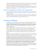
Component identification Front panel components Item Description 1 USB connectors (2) 2 Drive cage blank 3 SAS/SATA drives (8) 4 Front video connector (rack model only) 5 Systems Insight Display 6 Removable media bay 7 DVD-ROM drive 8 Optical drive blank Component identification 83
Front panel LEDs and buttons Item Description Status 1 Power On/Standby button and system power LED Green = Normal (system on) Amber = System in standby, but power still applied Off = Power cord not attached or power supply failure 2 Health LED Green = Normal (system on) Amber = System health is degraded Red = System health is critical.
Systems Insight Display LEDs The HP Systems Insight Display LEDs represent the system board layout. Item Description Status 1 Power cap To determine Power cap status, see "Systems Insight Display LED combinations (on page 85).
Systems Insight Display Health LED LED and color Processor (amber) Red System power LED Status Amber One or more of the following conditions may exist: • • • • Processor in socket X has failed. Processor X is not installed in the socket. Processor X is unsupported. ROM detects a failed processor during POST Processor (amber) Amber Green Processor in socket X is in a pre-failure condition. DIMM (amber) Red Green One or more DIMMs have failed.
Rear panel components Item Description 1 Mouse connector 2 Keyboard connector 3 Serial connector 4 iLO 2 connector 5 USB connectors (2) 6 NIC connectors (4) 7 PCI expansion slots 8 Reserved for PCI-X option kit 9 Video connector 10 Power supply bay 2 11 Power supply bay 1 (populated) Component identification 87
Rear panel LEDs Item Description Status 1 UID LED Blue = Activated Flashing blue = System is being managed remotely.
System board components Item Description 1 SD card slot 2 Power backplane connector 3 Processor 1 DIMM slots 4 Power supply connector 5 SAS connector B 6 SAS connector A 7 Front panel connector 8 Systems Insight Display connector 9 Front video connector 10 Front USB connector 11 Smart Array P410i memory module 12 Reserved 13 System battery 14 TPM connector 15 SATA connectors (6) 16 Slot 1 PCIe x8 (4, 2, 1) 17 Slot 2 PCIe2 x8 (4, 2, 1) 18 Slot 3 PCIe2 x16 (16, 8, 4, 2, 1
Item Description 26 Slot 10 PCIe2 x8 (8, 4, 2, 1) 27 Internal USB connector 28 Processor socket 2 29 Processor 2 DIMM slots 30 Power supply connector 31 Processor socket 1 (populated) DIMM slots DIMM slots are numbered sequentially (1 through 9) for each processor. The supported AMP modes use the letter assignments for population guidelines. DIMM identification IMPORTANT: This server does not support mixing RDIMMs and UDIMMs.
The memory subsystem may be populated with either RDIMMs or UDIMMs, but mixing the two types is not supported. To determine DIMM characteristics, use the label attached to the DIMM and the following illustration and table.
Position Description Function S5 Password protection override Off = No function On = Clears power-on password and administrator password S6 Invalidate configuration Off = Normal On = ROM treats the system configuration as invalid. S7 Reserved Reserved S8 Reserved Reserved S9 Reserved Reserved S10 Reserved Reserved When the system maintenance switch position 6 is set to the On position, the system is prepared to erase all system configuration settings from both CMOS and NVRAM.
• SFF hard drives • LFF hard drives Component identification 93
SAS and SATA hard drive LEDs Item Description Status 1 Fault/UID LED Amber = Drive failure Flashing amber = Fault-process activity Blue = Unit identification is active Off = No fault-process activity 2 Online/activity LED Green = Drive activity Flashing green = High activity on the drive or drive is being configured as part of an array Off = No drive activity SAS and SATA hard drive LED combinations Online/activity LED (green) Fault/UID LED (amber/blue) On, off, or flashing Alternating amber an
Online/activity LED (green) Fault/UID LED (amber/blue) Flashing regularly Off (1 Hz) Interpretation Do not remove the drive. Removing a drive may terminate the current operation and cause data loss. The drive is rebuilding, or it is part of an array that is undergoing capacity expansion or stripe migration. Flashing irregularly Amber, flashing regularly (1 Hz) The drive is active, but a predictive failure alert has been received for this drive. Replace the drive as soon as possible.
Battery pack LEDs Item Color Description 1 Green System Power LED. This LED is on when the system is powered up and 12 V system power is available. This power supply is used to maintain the battery charge and provide supplementary power to the cache microcontroller. 2 Green Auxiliary Power LED. This LED is on when 3.3V auxiliary voltage is detected. The auxiliary voltage is used to preserve BBWC data and is available any time that the system power cords are connected to a power supply.
LED3 pattern LED4 pattern Interpretation Off Flashing (1 Hz) The battery pack is below the minimum charge level and is being charged. Features that require a battery (such as write cache, capacity expansion, stripe size migration, and RAID migration) are unavailable temporarily until charging is complete. The recharge process takes between 15 minutes and 2 hours, depending on the initial capacity of the battery. Off On The battery pack is fully charged, and posted write data is stored in the cache.
1 Green LED 2 Amber LED Interpretation Off Off The flash code is corrupt.
• Six-bay LFF backplane • Eight-bay SFF backplane Drive cage Installation Pin setting 1 Standard No jumper 2 Optional 1-2* 3 Optional 2-3 *Optional drive cages ship with the jumper set across pins 1 and 2.
Cabling Storage device cabling guidelines CAUTION: To prevent damage to the equipment, be sure that the server is powered down, all cables are disconnected from the back of the server, and the power cord is disconnected from the grounded (earthed) AC outlet before installing devices. CAUTION: To prevent damage to electrical components, properly ground the server before beginning any installation procedure. Improper grounding can cause electrostatic discharge.
Item Description 3 SAS connector B 4 DVD-ROM drive 5 Hard drive cage 1, SAS connector 2 6 Hard drive cage 1, SAS connector 1 SAS hard drive cabling Item Description 1 Optional SAS controller 1, port 1 2 Optional SAS controller 1, port 2 3 Optional SAS controller 2, connector 1 4 Optional SAS controller 2, connector 2 5 SAS connector A 6 SAS connector B 7 Hard drive cage 3, SAS connector 2 8 Hard drive cage 3, SAS connector 1 9 Hard drive cage 2, SAS connector 2 10 Hard drive
Two-bay LFF drive cage cabling • Two-bay LFF drive cage cabling to an optional six-bay LFF backplane Item Description 1 Drive cage bay 1 power cable 2 Drive cage bay 3 power cable 3 SAS cable (connector A) 4 SAS cable (connector B) 5 LED cable • Two-bay LFF drive cage cabling to an optional SAS controller Cabling 102
Six-bay LFF backplane cabling • Drive cage bay 1 • Drive cage bay 2 Cabling 103
Eight-bay SFF drive cage cabling • Drive cage bay 1 • Drive cage bay 2 Cabling 104
• Drive cage bay 3 SAS expander cabling The colors are shown for illustration purposes only.
Item Description 2 SAS expander card, connectors E and F 3 SAS expander card, connectors G and H 4 SAS expander card, connectors A and B 5 System board SAS connectors A and B 6 Hard drive cage 3 7 Hard drive cage 2 8 Hard drive cage 1 Media device data cabling Item Description 1 SATA connectors 2 Slimline optical drive 3 DVD-ROM drive 4 Half-height media device Cabling 106
DVD-ROM drive cabling Slimline optical drive cabling Cabling 107
Power cabling Server power cabling (basic configuration) Item Description 1 Power supply backplane connector 2 24-pin power connector 3 Hard drive cage 1 4 DVD-ROM drive Cabling 108
Server power cabling (maximum configuration) The colors are shown for illustration purposes only.
Hard drive cage power cabling Item Description 1 24-pin power connector 2 Power supply backplane connector 3 Hard drive bay 1 (must use BP1 power cable) 4 Hard drive bay 2 (must use BP2 power cable) 5 Hard drive bay 3 (must use BP3 power cable) Cabling 110
Front panel cabling Item Description 1 Front USB connector 2 Front video connector 3 Systems Insight Display connector 4 Front panel connector Cabling 111
BBWC battery pack and FBWC capacitor pack cabling Cabling 112
Specifications Environmental specifications Specification Value Temperature range* Operating 10°C to 35°C (50°F to 95°F) Shipping -40°C to 70°C (-40°F to 158°F) Maximum wet bulb temperature 28°C (82.4°F) Relative humidity (noncondensing)** Operating 10% to 90% Nonoperating 5% to 95% * All temperature ratings shown are for sea level. An altitude derating of 1°C per 300 m (1.8°F per 1,000 ft) to 3,048 m (10,000 ft) is applicable. No direct sunlight allowed.
Specification Value Input requirements Rated input voltage 100 to 120 VAC, 200 to 240 VAC Rated input frequency 50 Hz to 60 Hz Rated input current 10 A at 100 VAC 4.
Rated input power 526 W at 100V AC input 505 W at 200V AC input BTUs per hour 1794 at 100V AC input 1725 at 200V AC input Power supply output Rated steady-state power 460 W at 100V to 120V AC input 460 W at 200V to 240V AC input Maximum peak power 460 W at 100V to 120V AC input 460 W at 200V to 240V AC input Specifications 115
Acronyms and abbreviations AMP Advanced Memory Protection BBWC battery-backed write cache CSR Customer Self Repair FBWC flash-backed write cache iLO Integrated Lights-Out IML Integrated Management Log LFF large form factor NCQ Native Command Queuing NMI nonmaskable interrupt NVRAM nonvolatile memory PCIe peripheral component interconnect express POST Power-On Self Test Acronyms and abbreviations 116
RBSU ROM-Based Setup Utility RDIMM registered dual in-line memory module SAS serial attached SCSI SATA serial ATA SFF small form factor SIM Systems Insight Manager TPM Trusted Platform Module UDIMM unregistered dual in-line memory module UID unit identification Acronyms and abbreviations 117
Documentation feedback HP is committed to providing documentation that meets your needs. To help us improve the documentation, send any errors, suggestions, or comments to Documentation Feedback (mailto:docsfeedback@hp.com). Include the document title and part number, version number, or the URL when submitting your feedback.
Index A access panel 31 additional information 80 air baffle 26, 34 B battery 89 battery cabling for BBWC 112 battery pack LEDs 96 battery pack, removing 33 battery-backed write cache (BBWC) 32, 33, 96 BBWC (battery-backed write cache) 32, 33, 96 BBWC battery pack 33 blue screen event 92 buttons 83 C cable management arm 29 cables 67, 68, 100 cabling 100, 102, 103, 104, 105, 106, 107, 108, 109, 110, 111, 112 cabling, storage system 100 cache module 32 capacitor pack 33, 97 components 16, 19, 25, 70, 83 co
HP HP HP HP Insight Diagnostics survey functionality 80 Insight Remote Support software 81 NC375i adapter 63 NC524SFP Dual Port 10GbE Module 65 I I/O bezel 68 illustrated parts catalog 16 iLO 2 activity LED 88 iLO 2 link LED 88 IML (Integrated Management Log) 81 Insight Diagnostics 80 Integrated Management Log (IML) 81 internal USB connector 89 J jumper settings 98 K keyboard connector 87 L LED, system power 27 LEDs 83, 84, 85, 88 LEDs, battery pack 96 LEDs, FBWC module 97 LEDs, hard drive 94 LEDs, SAS
server specifications 113 side panels, removing 38 six-bay LFF backplane 47, 103 slimline optical drive 43, 107 Smart Array P410i controller 89 specifications 113 specifications, environmental 113 specifications, server 113 static electricity 25 status lights, battery pack 96 storage system, cabling 100 switch, NMI 92 switches 92 symbols on equipment 25 system battery 69 system board components 89 system board replacement 70 system components 19, 83 system maintenance switch 89, 91, 92 system power LED 27,